 Pushpraj Mandloi
 Amarnath Hegde
- Department of Civil and Environmental Engineering, Indian Institute of Technology Patna, Patna, India
The concept of using Reinforced Earth (RE) walls for rail corridors is gaining popularity. As of now, very few nations have successfully adopted the RE walls for Railway infrastructure. These structures require good quality granular materials like sand for backfilling. However, due to the scarcity of good quality natural sand, research efforts are being made to look for cost effective alternatives to sand in backfill applications. The present study examines the possibilities of using the two sustainable materials, namely steel slag and construction and demolition waste (CDW), as backfills in RE walls subjected to harmonic train-induced load. In total, 63 separate full-scale numerical models of RE walls have been analyzed to understand the wall behavior with sustainable backfills subjected to different train speeds. The backfill materials were simulated with three different material models, namely, linear elastic, Mohr-Coulomb and Hardening Soil, for comparison. The results showed that the RE wall behavior is highly frequency-dependent. RE walls with steel slag and CDW backfills have shown 25% and 12% lesser deformations, respectively as compared to the sand backfill. Furthermore, reinforcement tensile forces in walls with sustainable backfills were found to be comparable to those of sand. The maximum deformation of the wall was observed when the fill materials were simulated with the Hardening Soil model. In overall, satisfactory performance of the RE wall was observed in the presence of sustainable backfill materials under Railway loading.
Introduction
Reinforced Earth walls are retaining structures that have been extensively used to support roadways, bridge abutments, railways, and other structures across the world (Lee and Wu, 2004; Tatsuoka et al., 2014; Lenart et al., 2016). In the U.S. transportation system only, around 850,000 m2 of reinforced Earth walls are added annually (Berg et al., 2009). These walls have been extensively used in different construction projects as a cost-effective infrastructure for load support and Earth retention (Hu and Luo, 2018). The massive demand of reinforced Earth (RE) walls is due to their cost-effectiveness, durability, flexibility, and low space requirement over conventional retaining walls. The wall performance is mainly governed by the quality of the backfill and its interaction with the reinforcement strips. These advantages of the RE wall drew the attention of researchers on this topic, and at present, a substantial number of studies on this subject have been published. As of now, the behavior of RE walls and its component under static conditions are well known (Hatami and Bathurst, 2005; Abdelouhab et al., 2011; Chau et al., 2012; Koerner and Koerner, 2018). However, only a few studies have investigated the response of RE walls under high-speed train (HST) loading (Payeur et al., 2015; Chawla and Shahu, 2021). Due to lack of thorough understanding, only a few nations have successfully adopted the RE walls for HST infrastructure.
At the same time, the increased demand of RE walls requires a huge volume of high-quality granular backfill material. Natural sand has been among the most often utilized material in construction as a fill material that meets the requirement of various design standards. Sand, on the other hand, is a globally over-exploited natural material that is not always readily available near construction sites. As a result of the increasing depletion of geo-materials, researchers and engineers have been pushed to examine and choose substitute materials for backfill applications.
A sustainable approach is a lucrative strategy that preserves the environment and reduces energy and natural resource usage (Pitt et al., 2009). Materials that aid in achieving such goals are known as sustainable materials. Sustainable materials, in general, are by-products of numerous industrial and building activities. Most of these materials are discarded into open landfills, creating a huge environmental concern. One of the finest methods to achieve sustainable goals is to utilize these materials in the infrastructure industry. This strategy safeguards the environment from the adverse effects of dumping and avoids the depletion of natural resources. Several by-products have recently been examined for large-scale infrastructure uses. These materials include recycled aggregates (Kisku et al., 2017; Mistri et al., 2020), fly ash (Aydin and Arel, 2017; Xu and Shi, 2018), shredded tires (Anburuvel, 2022; Bandyopadhyay et al., 2022) and pond ash (Le et al., 2018). Past studies have demonstrated that employing different waste materials in engineering structures leads to a substantial decrease in environmental pollution. The current study draws attention to two such sustainable materials, namely steel slag and construction and demolition waste (CDW), for their possible use in RE wall backfill applications.
The explosive growth of civilization results in an enormous amount of industrial waste. Steel slag is one such by-product obtained from steel-making industries. Several studies highlighted the utilization of steel slag in ceramic production (Rahou et al., 2022), railway ballast (Delgado et al., 2019; Esmaeili et al., 2020; Jing et al., 2020), highway sub-base (Wu et al., 2019), aggregates (Shi, 2004) and concrete production (Qasrawi et al., 2009; Wang et al. (2013). On the other hand, current infrastructural development is resulting in an increase in CDW production. Depending on the nature of the construction involved, CDW may include materials such as aggregates, glass, wood, concrete, and bricks. Construction and demolition wastes are one of the major waste materials produced in the world with large portion of it going into landfills (Rao et al., 2007; Zhao et al., 2010). Various studies were conducted to highlight different applications of CDW in road construction (Xuan et al., 2015; Silva et al., 2019; Mehrjardi et al., 2020) and concrete production (Martín-Morales et al., 2011; Silva et al., 2014; Bravo et al., 2015; Akhtar and Sarmah, 2018; Sarkar and Hegde, 2022). Satisfactory performance of RE wall with CDW backfill was reported by Santos et al. (2013). However, the studies on the use of steel slag and CDW as backfill in RE walls subjected to train-induced loading conditions are scanty.
The present study investigates the feasibility of using steel slag and CDW as a substitute for sand in RE walls supporting the rail corridor. To achieve this goal, finite element based numerical simulations have been performed. The behavior of RE walls with steel slag and CDW backfills has been compared with conventional sand backfill. In addition, three distinct material models have been employed to simulate the sustainable backfill materials for providing clear comparisons and recommendations.
Material characterization
In the present study, three materials, namely sand, steel slag, and CDW have been used. Figure 1 presents photographs of the materials used. The particle size distribution of the materials was performed as per ASTM, 2007 as shown in Figure 2. According to the Unified Soil Classification System (USCS), the sand is classified as poorly-graded sand (SP). Whereas steel slag and CDW were classified as well-graded sand (SW). The specific gravity of sand, steel slag, and CDW were found to be 2.58, 3.37, and 2.43, respectively. Similarly, the coefficient of permeability of sand, steel slag, and CDW were found to be 1.51 × 10⁻⁴ m/s, 6.76 × 10⁻⁵ m/s, and 6.47 × 10⁻⁶ m/s, respectively.

FIGURE 1. Backfill materials; (A) sand, (B) CDW, (C) steel slag.
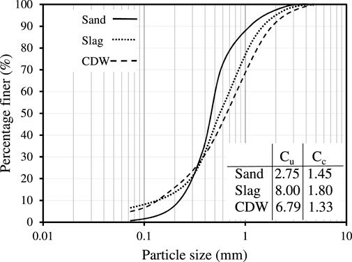
FIGURE 2. Particle size distribution curve.
Numerical study
The RE wall geometry adopted in the study was borrowed from Payeur et al. (2015). Figure 3 represents the model geometry adopted in the current study. The geometry consists of a 3.75 m high RE wall, with five numbers of reinforcement strips embedded in the backfill. The reinforcing strips were 3.5 m long and laid with 0.75 m vertical spacing.
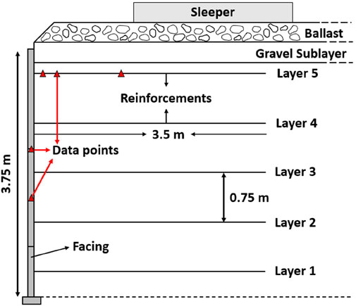
FIGURE 3. Full-scale RE wall model geometry (Redrawn from Payeur et al., 2015).
Figure 4 shows the PLAXIS2D numerical model used in the analysis. The numerical model was developed using the staged construction procedure. Reinforcements were modeled with elastic geogrid elements. The ballast and sub-layer were simulated using the linear elastic constitutive model. Modelling the ballast as a linear visco-elastic continuum leads to a significant simplification of the true behaviour of the material in case of dynamic loading (Payeur et al., 2015). This simplification is appropriate as long as the numerical results are analysed in terms of backfill response rather than ballast layer response. The material parameters of various components were borrowed from the original study (Payeur et al., 2015) and are listed in Table 1.
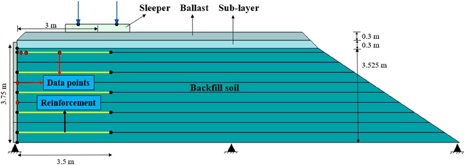
FIGURE 4. Numerical model geometry.
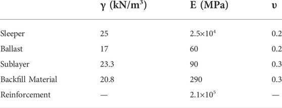
TABLE 1. Material properties (Borrowed from Payeur et al., 2015).
Rayleigh model was used to compute the material damping (Semblat and Pecker, 2009). The values of damping coefficients were set for each frequency to attain the damping ratio (ξ) of 5%. Harmonic loading was applied to the sleeper with a number of cycles large enough to reach an established harmonic regime to simulate the train-induced load (10 cycles). Before applying the harmonic load, the model was set to run under its self-weight without any external load. After which, the wall deformation and nodal displacement were set to zero to obtain the incremental deformations induced by the train-load only.
Train load simulation
The load imparted on the rail-wheel interface by moving wheel loads is greater than the wheel load at rest (Van Dyk et al., 2017). Therefore, to calculate the dynamic wheel load generated by a moving train, the static wheel load is multiplied by a load factor known as the impact factor or dynamic wheel load factor. Eq. 1 represents the relationship between design axle load (Pd), static axle load (Ps), and impact factor (ɸ').
Doyle, (1980) summarised the impact factor given by various researchers and organizations. The impact factor value was developed empirically using field data. Train speed is the most crucial parameter that governs the magnitude of the impact factor. In addition, vehicle parameters such as wheel diameter, locomotive maintenance condition, static wheel load, and track parameters influence the impact factor (Van Dyk et al., 2017).
The impact factor used to calculate the dynamic load in the current study was obtained as per the guidelines of American Railway Engineering Association (AREA, 1978). Accordingly, the impact factor is a function of train speed and wheel diameter, as shown in Eq. (2).
where ‘V' is the speed of the train (kmph), and ‘Dw’ is the wheel diameter (m).
The maximum value of static wheel load carried by one sleeper is calculated by considering the load distribution among five adjacent sleepers (USACE, 2000). Figure 5 shows the schematic distribution of wheel load on the five adjacent sleepers.
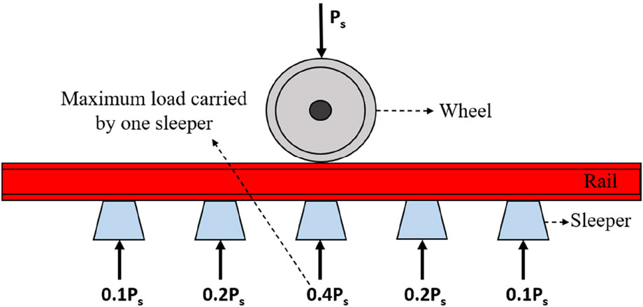
FIGURE 5. Distribution of wheel load on sleepers (USACE, 2000).
Based on the above approach, the maximum value of the design dynamic wheel load (kN) acting on a single sleeper was calculated. Table 2 shows the obtained values of design dynamic load calculated for different train locomotive weights (20 t, 25 t, and 30 t) and train coach weights (13 t, 16.25 t) at various train speeds. Diameter of the wheel was considered as 0.97 m. The selected weights of the locomotives and the train coaches are in accordance with Research Design and Standards Organization (RDSO) for passenger trains (RDSO, 2017).
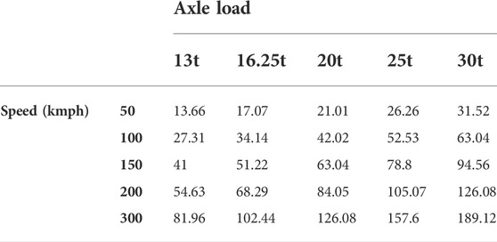
TABLE 2. Maximum value of design dynamic load (kN) for different train speeds (kmph) and axle loads (t).
The maximum value of the design dynamic axle load used in the current numerical analysis was 50 kN. Table 3 illustrates the design speed values derived for different axle loads corresponding to the 50 kN design dynamic load. The dynamic load was applied at different loading frequencies (5 Hz–35 Hz) in the numerical model. These frequencies correspond to the first natural frequencies of the rail displacements for a train speed up to 300 km/h (Degrande and Schillemans, 2001). These frequencies were calculated by taking the ratio of characteristic lengths of a train (wheel to wheel length and bogie to bogie length) and the train’s speed. Figure 6 shows two dynamic load cycles applied in the current study at 25 Hz frequency.
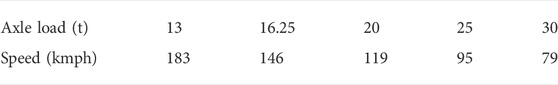
TABLE 3. Design speeds for various axle loads corresponding to 50 kN design dynamic load.
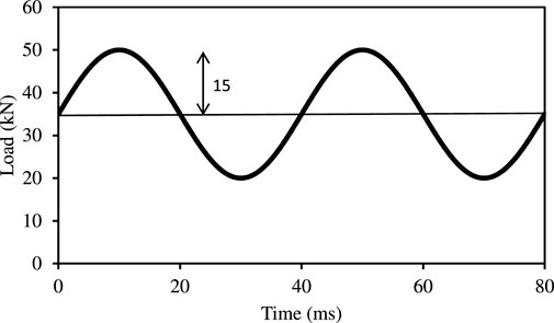
FIGURE 6. Dynamic load applied on the sleeper at 25 Hz loading frequency.
Validation
Firstly, numerical model of the RE wall was validated with the results of Payeur et al. (2015). In the original study, the numerical modeling was performed in the software package Plaxis3D, assuming visco-elastic constitutive laws for each component of the RE wall. Whereas, in the current study, Plaxis2D was used to perform the numerical simulations. For plain stain problems like RE walls, most often the 2D and 3D analyses provide the similar results (Bourgeois et al., 2011). However, the use of the similar material model and input parameters is most important in the original model and the model to be validated. In the present study, the RE wall geometry, structural details, and material properties similar to the original study of Payeur et al. (2015) were considered in the simulation. The linear elastic material, similar to the original study was used in the present model to simulate the behavior of the backfill materials. Horizontal facing displacement of wall and the tensile force in the topmost geogrid were compared. The horizontal facing displacement of the wall was captured from nodes situated at 1.5 m and 2.25 m wall elevation. Tensile force in the reinforcement strip was obtained from three locations, located at 0.1, 0.4, and 1.4 m distance from the wall facing. All the data points at which the analysis was carried out are shown in Figure 4. Numerical data of horizontal facing displacement and the tensile force in the reinforcement strip, obtained from the current study were compared with Payeur et al. (2015), as shown in Figures 7, 8.
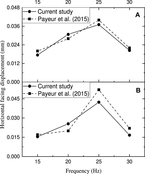
FIGURE 7. Comparison of horizontal facing displacement; (A) at 1.5 m wall elevation, (B) at 2.25 m wall elevation.
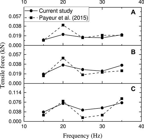
FIGURE 8. Comparison of tensile force in the topmost geogrid at three different distances from the wall facing; (A) 0.1 m, (B) 0.4 m, (C) 1.4 m.
The results obtained from the current study were in good agreement with the numerical data obtained from Payeur et al. (2015). The minor difference in the results of the present study and the original study is due to the approximation of 3D analysis into 2D analysis. The validated numerical model was further used to analyze the performance of the RE wall using sustainable backfill materials. Using the modeling approach similar to the one used in the validation, 63 different RE wall cases were analyzed. These cases consist of 3 different backfill materials, each simulated by 3 distinct material models. Each of these scenarios was tested amongst 7 different loading frequencies.
Result and discussions
In this section, the performance analysis of the RE wall was carried out using three different backfill materials, sand, steel slag, and CDW. Out of which, sand is the standard backfill material used for comparing the performance of sustainable backfills. The behavior of the RE wall has been compared for backfill materials simulated with different material models. The backfill soil parameters used in the validated model were replaced with the properties of sand, steel slag, and CDW obtained from different laboratory tests as listed in Table 4. A detailed description of the determination of the material properties has been provided elsewhere by Mandloi et al. (2022). The properties of other RE wall components were kept unchanged from the validated model.
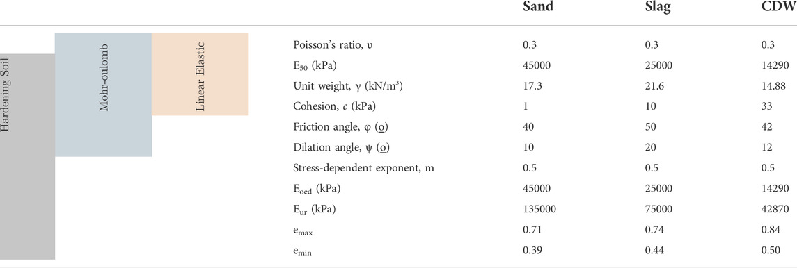
TABLE 4. Backfill soil parameters used for different materials (Borrowed from Mandloi et al., 2022).
The response of the wall was compared in terms of horizontal facing displacement, reinforcement tensile force and reinforcement strain. The horizontal facing displacement was measured at two wall elevations, i.e., 1.5 m and 2.25 m. Whereas the tensile force was measured in the topmost strip at two locations, i.e., 0.1 and 1.4 m distance from the facing.
Effect of material models on wall behavior
Previous studies have demonstrated the potential of using various constitutive models to simulate the backfill material in numerical simulations. Linear elastic, Mohr-Coulomb, Lade’s single Hardening model, Hardening soil model, and Hardening soil small strain model were utilized by researchers to simulate the behavior of backfill materials in RE wall applications (Hatami and Bathurst, 2005; Huang et al., 2009; Payeur et al., 2015; Huynh et al., 2022; Sarkar and Hegde, 2022). In this study, the behaviour of the RE wall under railway loading has been analyzed by considering three different constitutive models, namely, Linear Elastic (LE), Mohr-Coulomb (MC), and Hardening soil (HS).
The stress-strain response of soil mass is typically non-linear. The shear strength and stiffness of a soil mass usually depends upon the stress history, strain level and stress level. The stress-strain response in the LE model is approximated by Hooke’s law. Figure 9A shows the stress-strain response for elastic perfectly plastic MC model. The linear-elastic part of the stress-strain curve is approximated by Hooke’s law. Whereas, the perfectly-plastic part is estimated based on Mohr-Coulomb failure criterion. Mohr-Coulomb model is the most preferred model to simulate backfill materials, as it is simple to use. Moreover, it efficiently captures the stress-dependent failure conditions (Mohsan et al., 2021). However, it is not capable of capturing the hardening before failure, stress-dependent stiffness and non-linear elasticity. On the contrary, HS model is capable of capturing all the aforesaid phenomenon including plastic straining and elastic unloading/reloading (Lai et al., 2020). In the HS model, the stress-strain behavior of the soil mass is approximated by a hyperbolic function as shown in Figure 9B. Input parameters used for each constitutive model are listed in Table 4. Detailed discussion on the calculation and implementation of HS model has been provided elsewhere by Mandloi et al. (2022).
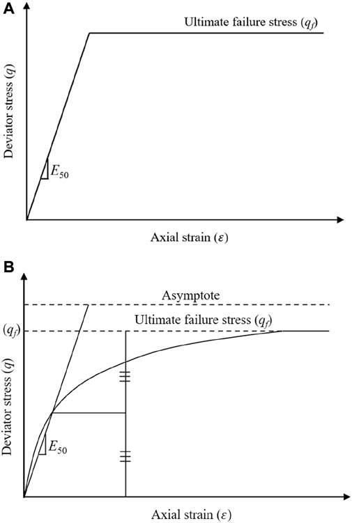
FIGURE 9. Representation of constitutive models; (A) Mohr-Coulomb, (B) Hardening soil.
Horizontal facing displacement of RE wall is an important criterion to analyze the wall behavior. Wall facing displacement is mainly governed by the properties of facing, reinforcement, and backfill material. The behavior of the RE wall when the backfill soil is simulated by three different constitutive models has been compared. For the comparison, wall-facing displacement above 1.5 m wall elevation was used. Figure 10 shows the comparison of horizontal facing displacement of the wall for different material models. For all the materials, the wall-facing displacement trend was nearly identical for all frequencies. Therefore, the wall behavior subjected to 15 Hz, 20 Hz, and 25 Hz loading frequencies was only presented.
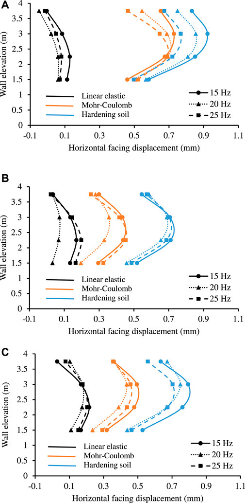
FIGURE 10. Comparison of horizontal facing displacement using different constitutive models; (A) sand, (B) slag, (C) CDW.
For each material used, the maximum wall facing deformation was observed in the HS model, followed by the MC and LE models. The amplification of the deformation in case of the HS and MC models as compared to the LE model was calculated using the parameter termed as amplification factor. It is the ratio of peak deformation observed in the HS and MC model to that of the LE model. Table 5 lists the amplification factors for different cases. Maximum amplification was observed for sand as compared to sustainable materials. The peak values of facing displacement were observed close to 3 m wall elevation for the non-linear models (HS and MC). Whereas, with the LE model, the peak values were observed at 2.25 m wall elevation.
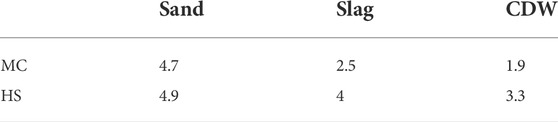
TABLE 5. Amplification factors.
Figure 11 shows the horizontal displacement contours of the RE wall with different backfill materials and simulated by different models. All three backfill materials exhibited approximately similar results in case of LE model. This is because the shear strength parameters of the backfills are not a part of the formulation in the linear elastic model. Only modulus of elasticity and Poisson’s ratio are essential to simulate the behavior of materials. For backfill materials simulated with the LE model, the maximum facing displacement was found to converge at the centre of the wall facing. On the other hand, when the backfill materials were modeled by non-linear models (MC and HS), the maximum facing displacement was observed at the top portion of the wall. Maximum deformation in the top portion of the wall is close to reality as it was demonstrated in many of the previous studies.
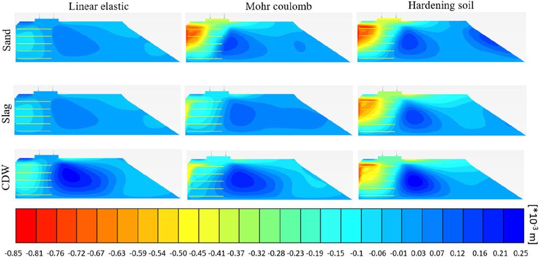
FIGURE 11. Horizontal displacement contours for 25 Hz loading frequency.
Peak values of tensile force in the topmost reinforcement strip for different cases are listed in Table 6. These peak values were observed near the centre of strip for each material when the LE material model was used to simulate backfill. Whereas, when MC and HS models were used, these peaks were observed near the facing. Previous studies have shown that the deformations near the facing are higher as compared to other portions of the RE wall. Higher forces in the reinforcements were observed when non-linear models (HS and MC) were used. Furthermore, the HS model and the MC model were able to capture the differential settlement between the facing-backfill interface. The observed differential settlement in case of HS model was found to be higher as compared to the MC model.
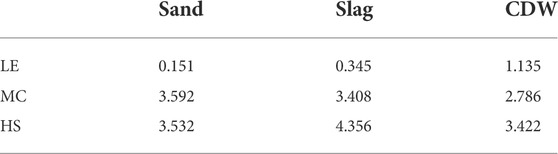
TABLE 6. Peak reinforcement tensile force (kN) in topmost strip for different cases.
Effect of frequency of loading on wall behavior
In this section, the behavior of the RE wall has been analyzed under varying load frequencies between 5 and 35 Hz, which corresponds to the train speed up to 300 km/h. Furthermore, the performance of RE wall with sustainable backfill has been presented and compared with natural backfill sand.
Figure 12 shows the comparison of horizontal facing displacement of wall at two different wall elevations with varying frequencies for the HS model. The results are found to be frequency dependent. However, no resonance was observed in wall deformation for each backfill material used. Instead, a downward trend in wall deformations was observed with the increase in load frequencies. Peak values of horizontal facing displacement were 1.06, 0.8, and 0.926 mm for sand, slag, and CDW, respectively, at 3 m wall elevation for each material. Peak values of horizontal facing displacement were reduced by 25% and 12% when slag and CDW were used as compared to sand. This can be attributed to higher shear strength of the sustainable materials as compared to sand (Mandloi et al., 2022; Sarkar and Hegde, 2022).
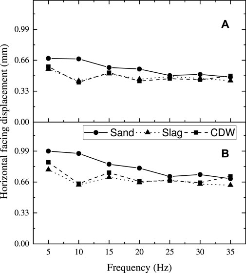
FIGURE 12. Horizontal facing displacement at different wall elevations using hardening soil model; (A) 1.5 m, (B) 2.25 m.
Reinforcements are one of the important components of the RE wall, which contributes to its strength. Backfill soil is weak in tension and the reinforcement strips provide adequate tensile strength to the backfill soil, leading to improved RE wall performance. The reinforcements also increase the load carrying capacity of backfill and reduces the overall settlement (Hegde and Palsule, 2020). Figure 13 shows the tensile force in the topmost reinforcement at two different distances from the facing. By changing the frequency of loading, no discernible changes in the reinforcement tensile force were observed. Reinforcement tensile force in RE walls with sustainable backfills was found to be comparable to those of sand, near the wall facing. Whereas, at the centre of the reinforcement strip, the reinforcement tensile forces were less in RE walls with sustainable backfills, compared to sand.
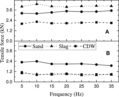
FIGURE 13. Tensile force in the topmost strip at different distances from the wall facing for hardening soil model; (A) 0.1 m, (B) 1.4 m.
Figure 14 shows the reinforcement strains of the top 3 reinforcing layers in the horizontal direction when the materials were simulated by the HS model subjected to 25 Hz loading frequency. For each material, the fourth layer, located at 2.625 m height experienced maximum reinforcement strains. For each case, maximum strains were captured close to the back of the facing. This is mainly due to the differential settlement at the facing-backfill interface and wall-facing rotation. Such results are in accordance with the observation reported by Mandloi et al. (2022). In comparison to sand backfills, lesser strain was observed in the reinforcements in case of slag and CDW backfills. In the steel slag backfilled RE wall, a major portion of the developed stresses was shared by the backfill soil itself. This is because steel slag has high shear strength due to which the reinforcement elongations were reduced. Although CDW has a lower shear strength than slag, the strains in CDW backfilled RE walls was found to be lesser. This is attributed to the lower self-weight of CDW, which decreased the stresses imposed on reinforcements. In comparison to sand, peak strains were reduced by 6.3% and 6.8%, respectively, for steel slag and CDW materials.
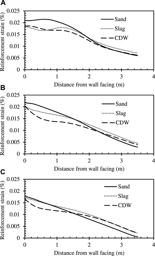
FIGURE 14. Horizontal strains in reinforcement strips situated at different wall elevations subjected to 25 Hz load frequency (A) 3.375 m, (B) 2.625 m, (C) 1.875 m.
Conclusion
The numerical analyses were performed on RE walls backfilled with different sustainable materials, namely steel slag and CDW under Railway loading. The behavior of the RE wall with sustainable backfills was compared with the standard material sand. Following are some of the conclusions drawn from the study.
• RE walls with sustainable backfills, showed better performance as compared to RE walls with natural backfill material sand. Peak values of horizontal facing displacement were reduced by 25% and 12% respectively for slag and CDW backfill cases as compared to sand. Similarly, peak reinforcement strains were reduced by 6.3% and 6.8% respectively for slag and CDW cases as compared to sand.
• RE wall behavior was found to be highly dependent on the loading frequency. Horizontal facing displacement were decreased in the range of 20%–30% due to the increase in the frequency of loading from 5 to 35 Hz. Whereas, minimal change in the reinforcement tensile forces was observed with the change in frequency of loading.
• A highly conservative results in terms of wall facing displacement and reinforcement strains were obtained with LE material models for all the backfills. When the HS model was used, maximum facing deformations were observed. The peak facing deformations with LE models were observed close to the centre of the wall at 2.25 m wall elevation. Whereas for MC and HS models, the peak facing deformations were observed at the top portion of the wall, at 3 m wall elevation.
• Non-linear models (MC and HS) were able to capture the differential settlement at the backfill and wall facing interface. In overall, it can be concluded that the behavior of RE wall can be better captured when the backfill soil is simulated by HS model, followed by the MC model.
Data availability statement
The datasets generated for this study are available on request to the corresponding author.
Author contributions
PM performed the studies and prepared the manuscript based on the inputs and guidance of AH. PM and AH reviewed and accepted the final version.
Acknowledgments
The Authors would like to thank and acknowledge Indian Institute of Technology Patna and Department of Higher Education (Govt. of India) for providing the funding for present research work for which no specific grant number has been allotted.
Conflict of interest
The authors declare that the research was conducted in the absence of any commercial or financial relationships that could be construed as a potential conflict of interest.
Publisher’s note
All claims expressed in this article are solely those of the authors and do not necessarily represent those of their affiliated organizations, or those of the publisher, the editors and the reviewers. Any product that may be evaluated in this article, or claim that may be made by its manufacturer, is not guaranteed or endorsed by the publisher.
References
Abdelouhab, A., Dias, D., and Freitag, N. (2011). Numerical analysis of the behaviour of mechanically stabilized Earth walls reinforced with different types of strips. Geotext. Geomembranes 29 (2), 116–129. doi:10.1016/j.geotexmem.2010.10.011
Akhtar, A., and Sarmah, A. K. (2018). Construction and demolition waste generation and properties of recycled aggregate concrete: A global perspective. J. Clean. Prod. 186, 262–281. doi:10.1016/j.jclepro.2018.03.085
Anburuvel, A. (2022). Crushed stone partially substituted with shredded-waste tyres of motorcycles for low-volume road base construction: A feasibility study in Sri Lanka. Innov. Infrastruct. Solut. 7 (1), 123. doi:10.1007/s41062-021-00721-8
AREA (1978). Manual of recommended practice. Washington D.C., USA: American Railway Engineering Association.
ASTM (2007). D 442-63: Standard test method for particle-size analysis of soils. West Conshohocken, PA, USA: ASTM International.
Aydin, E., and Arel, H. Ş. (2017). Characterization of high-volume fly-ash cement pastes for sustainable construction applications. Constr. Build. Mater. 157, 96–107. doi:10.1016/j.conbuildmat.2017.09.089
Bandyopadhyay, T. S., Chakrabortty, P., and Hegde, A. (2022). Dynamic response of the mechanically stabilized earth walls with different reinforcement and backfill conditions. Int. J. Civ. Eng., 1–19. doi:10.1007/s40999-022-00761-w
Berg, R. R., Samtani, N. C., and Christopher, B. R. (2009). Design of mechanically stabilized earth walls and reinforced soil slopes–Volume II. Washington, DC, USA, No: Federal Highway Administration. Department of Transportation. FHWA-NHI-10-025.
Bourgeois, E., Soyez, L., and Le Kouby, A. (2011). Experimental and numerical study of the behavior of a reinforced-Earth wall subjected to a local load. Comput. Geotechnics 38 (4), 515–525. doi:10.1016/j.compgeo.2011.02.017
Bravo, M., De Brito, J., Pontes, J., and Evangelista, L. (2015). Mechanical performance of concrete made with aggregates from construction and demolition waste recycling plants. J. Clean. Prod. 99, 59–74. doi:10.1016/j.jclepro.2015.03.012
Chau, T. L., Bourgeois, E., and Corfdir, A. (2012). Finite element analysis of the effect of corrosion on the behavior of reinforced Earth walls. Int. J. Numer. Anal. Methods Geomech. 36 (15), 1741–1756. doi:10.1002/nag.1095
Chawla, S., Shahu, J. T., and kumar, S. (2021). Analysis of cyclic deformation and post-cyclic strength of reinforced railway tracks on soft subgrade. Transp. Geotech. 28, 100535. doi:10.1016/j.trgeo.2021.100535
Degrande, G., and Schillemans, L. (2001). Free field vibrations during the passage of a Thalys high-speed train at variable speed. J. sound Vib. 247 (1), 131–144. doi:10.1006/jsvi.2001.3718
Delgado, B. G., da Fonseca, A. V., Fortunato, E., and Maia, P. (2019). Mechanical behavior of inert steel slag ballast for heavy haul rail track: Laboratory evaluation. Transp. Geotech. 20, 100243. doi:10.1016/j.trgeo.2019.100243
Doyle, N. F. (1980). Railway track design: A review of current practice. BHP melbourne research laboratories. Canberra: Australian Government Publisher Service.
Esmaeili, M., Yousefian, K., and Asgharzadeh Ghahroudi, P. (2020). An investigation of abrasion and wear characteristics of steel slag and granite ballasts. Proc. Institution Civ. Eng. - Constr. Mater. 173 (1), 41–12. doi:10.1680/jcoma.17.00044
Hatami, K., and Bathurst, R. J. (2005). Development and verification of a numerical model for the analysis of geosynthetic-reinforced soil segmental walls under working stress conditions. Can. Geotech. J. 42 (4), 1066–1085. doi:10.1139/t05-040
Hegde, A. M., and Palsule, P. S. (2020). Performance of geosynthetics reinforced subgrade subjected to repeated vehicle loads: Experimental and numerical studies. Front. Built Environ. 6, 15. doi:10.3389/fbuil.2020.00015
Hu, B., and Luo, Z. (2018). Life-cycle reliability-based assessment of internal stability for mechanically stabilized Earth walls in a heavy haul railway. Comput. Geotechnics 101, 141–148. doi:10.1016/j.compgeo.2018.04.023
Huang, B., Bathurst, R. J., and Hatami, K. (2009). Numerical study of reinforced soil segmental walls using three different constitutive soil models. J. Geotech. Geoenviron. Eng. 135 (10), 1486–1498. doi:10.1061/(asce)gt.1943-5606.0000092
Huynh, Q. T., Lai, V. Q., Boonyatee, T., and Keawsawasvong, S. (2022). Verification of soil parameters of hardening soil model with small-strain stiffness for deep excavations in medium dense sand in Ho Chi Minh City, Vietnam. Innov. Infrastruct. Solut. 7 (1), 15. doi:10.1007/s41062-021-00621-x
Jing, G., Wang, J., Wang, H., and Siahkouhi, M. (2020). Numerical investigation of the behavior of stone ballast mixed by steel slag in ballasted railway track. Constr. Build. Mater. 262, 120015. doi:10.1016/j.conbuildmat.2020.120015
Kisku, N., Joshi, H., Ansari, M., Panda, S. K., Nayak, S., and Dutta, S. C. (2017). A critical review and assessment for usage of recycled aggregate as sustainable construction material. Constr. Build. Mater. 131, 721–740. doi:10.1016/j.conbuildmat.2016.11.029
Koerner, R. M., and Koerner, G. R. (2018). An extended data base and recommendations regarding 320 failed geosynthetic reinforced mechanically stabilized Earth (MSE) walls. Geotext. Geomembranes 46 (6), 904–912. doi:10.1016/j.geotexmem.2018.07.013
Lai, V. Q., Le, M. N., Huynh, Q. T., and Do, T. H. (2020). “Performance analysis of a combination between D-wall and secant pile wall in upgrading the depth of basement by Plaxis 2D: A case study in Ho Chi Minh city,” in Icscea 2019 (Singapore: Springer), 745–755.
Le, T. H. M., Dae-Wook, P., and Jung-Woo, S. (2018). Evaluation of ponded ash as a sustainable backfill material. J. Mat. Civ. Eng. 30 (8), 04018158. doi:10.1061/(ASCE)MT.1943-5533.0002359
Lee, K. Z., and Wu, J. T. (2004). A synthesis of case histories on GRS bridge-supporting structures with flexible facing. Geotext. Geomembranes 22 (4), 181–204. doi:10.1016/j.geotexmem.2004.03.002
Lenart, S., Kralj, M., Medved, S. P., and Šuler, J. (2016). Design and construction of the first GRS integrated bridge with FHR facings in Europe. Transp. Geotech. 8, 26–34. doi:10.1016/j.trgeo.2016.07.003
Mandloi, P., Sarkar, S., and Hegde, A. (2022). Performance assessment of mechanically stabilised Earth walls with sustainable backfills. Proc. Institution Civ. Eng. - Eng. Sustain., 1–17. doi:10.1680/jensu.22.00012
Martín-Morales, M., Zamorano, M., Ruiz-Moyano, A., and Valverde-Espinosa, I. (2011). Characterization of recycled aggregates construction and demolition waste for concrete production following the Spanish Structural Concrete Code EHE-08. Constr. Build. Mater. 25 (2), 742–748. doi:10.1016/j.conbuildmat.2010.07.012
Mehrjardi, G. T., Azizi, A., Haji-Azizi, A., and Asdollafardi, G. (2020). Evaluating and improving the construction and demolition waste technical properties to use in road construction. Transp. Geotech. 23, 100349. doi:10.1016/j.trgeo.2020.100349
Mistri, A., Bhattacharyya, S. K., Dhami, N., Mukherjee, A., and Barai, S. V. (2020). A review on different treatment methods for enhancing the properties of recycled aggregates for sustainable construction materials. Constr. Build. Mater. 233, 117894. doi:10.1016/j.conbuildmat.2019.117894
Mohsan, M., Vardon, P. J., and Vossepoel, F. C. (2021). On the use of different constitutive models in data assimilation for slope stability. Comput. Geotechnics 138, 104332. doi:10.1016/j.compgeo.2021.104332
Payeur, J. B., Corfdir, A., and Bourgeois, E. (2015). Dynamic behavior of a Mechanically Stabilized Earth wall under harmonic loading: Experimental characterization and 3D finite elements model. Comput. Geotechnics 65, 199–211. doi:10.1016/j.compgeo.2014.12.001
Pitt, M., Tucker, M., Riley, M., and Longden, J. (2009). Towards sustainable construction: Promotion and best practices. Constr. Innov. 9 (2), 201–224. doi:10.1108/14714170910950830
Qasrawi, H., Shalabi, F., and Asi, I. (2009). Use of low CaO unprocessed steel slag in concrete as fine aggregate. Constr. Build. Mater. 23 (2), 1118–1125. doi:10.1016/j.conbuildmat.2008.06.003
Rahou, J., Rezqi, H., El Ouahabi, M., and Fagel, N. (2022). Characterization of Moroccan steel slag waste: The potential green resource for ceramic production. Constr. Build. Mater. 314, 125663. doi:10.1016/j.conbuildmat.2021.125663
Rao, A., Jha, K. N., and Misra, S. (2007). Use of aggregates from recycled construction and demolition waste in concrete. Resour. conservation Recycl. 50 (1), 71–81. doi:10.1016/j.resconrec.2006.05.010
RDSO (2017). Indian railway standard code of practice for the design of steel or wrought iron bridges carrying rail, road or pedestrian traffic.
Santos, E. C., Palmeira, E. M., and Bathurst, R. J. (2013). Behaviour of a geogrid reinforced wall built with recycled construction and demolition waste backfill on a collapsible foundation. Geotext. Geomembranes 39, 9–19. doi:10.1016/j.geotexmem.2013.07.002
Sarkar, S., and Hegde, A. (2022). Performance evaluation of geogrid reinforced recycled marginal backfill materials in triaxial test conditions. Int. J. Geosynth. Ground Eng. 8 (4), 48. doi:10.1007/s40891-022-00395-x
Sarkar, S., and Hegde, A. (2022). Strength enhancement of geogrid reinforced marginal backfill materials in triaxial condition. Geo-Congress 2022, 467–476. doi:10.1061/9780784484012.048
Semblat, J. F., and Pecker, A. (2009). Waves and vibrations in soils, 13.Earthquakes, traffic, shocks.
Shi, C. (2004). Steel slag—Its production, processing, characteristics, and cementitious properties. J. Mat. Civ. Eng. 1616 (3), 230–236. doi:10.1061/(asce)0899-1561(2004)16:3(230)
Silva, R. V., De Brito, J., and Dhir, R. K. (2014). Properties and composition of recycled aggregates from construction and demolition waste suitable for concrete production. Constr. Build. Mater. 65, 201–217. doi:10.1016/j.conbuildmat.2014.04.117
Silva, R. V., De Brito, J., and Dhir, R. K. (2019). Use of recycled aggregates arising from construction and demolition waste in new construction applications. J. Clean. Prod. 236, 117629. doi:10.1016/j.jclepro.2019.117629
Tatsuoka, F., Tateyama, M., Koseki, J., and Yonezawa, T. (2014). Geosynthetic-reinforced soil structures for railways in Japan. Transp. Infrastruct. Geotech. 1 (1), 3–53. doi:10.1007/s40515-013-0001-0
USACE (2000). Railroad design and rehabilitation. Washington, D.C.USA: Corps of Engineers.U.S. Army.
Van Dyk, B. J., Edwards, J. R., Dersch, M. S., Ruppert, C. J., and Barkan, C. P. (2017). Evaluation of dynamic and impact wheel load factors and their application in design processes. Proc. Institution Mech. Eng. Part F J. Rail Rapid Transit 231 (1), 33–43. doi:10.1177/0954409715619454
Wang, Q., Yan, P., Yang, J., and Zhang, B. (2013). Influence of steel slag on mechanical properties and durability of concrete. Constr. Build. Mater. 47, 1414–1420. doi:10.1016/j.conbuildmat.2013.06.044
Wu, J., Liu, Q., Deng, Y., Yu, X., Feng, Q., and Yan, C. (2019). Expansive soil modified by waste steel slag and its application in subbase layer of highways. Soils Found. 59 (4), 955–965. doi:10.1016/j.sandf.2019.03.009
Xu, G., and Shi, X. (2018). Characteristics and applications of fly ash as a sustainable construction material: A state-of-the-art review. Resour. Conservation Recycl. 136, 95–109. doi:10.1016/j.resconrec.2018.04.010
Xuan, D. X., Molenaar, A. A. A., and Houben, L. J. M. (2015). Evaluation of cement treatment of reclaimed construction and demolition waste as road bases. J. Clean. Prod. 100, 77–83. doi:10.1016/j.jclepro.2015.03.033
Zhao, W., Leeftink, R. B., and Rotter, V. S. (2010). Evaluation of the economic feasibility for the recycling of construction and demolition waste in China—the case of chongqing. Resour. Conservation Recycl. 54 (6), 377–389. doi:10.1016/j.resconrec.2009.09.003
Nomenclature
Dw Wheel diameter (m)
c Cohesion (kPa)
Cc Coefficient of gradation
Cu Uniformity coefficient
emax Maximum void ratio
emin Minimum void ratio
E50 Stiffness modulus at 50% failure stress (kPa)
Eur Unloading/Reloading stiffness (kPa)
Eoed Oedometer stiffness (kPa)
m Power of stress dependency of stiffness
Pd Design dynamic axle load (kN)
Ps Static axle load (kN)
qf Ultimate failure stress (kPa)
V Speed of train (kmph)
υ Poisson’s ratio
ϕ Soil friction angle (°)
ɸ
ψ Dilation angle (°)
γ Unit weight of soil (kN/m3)
ξ Damping ratio
Keywords: reinforced earth, railway loading, sustainable materials, steel slag, construction and demolition waste, Mohr-Coulomb, hardening soil
Citation: Mandloi P and Hegde A (2022) Performance evaluation of reinforced earth walls with sustainable backfills subjected to railway loading. Front. Built Environ. 8:1048079. doi: 10.3389/fbuil.2022.1048079
Received: 19 September 2022; Accepted: 04 October 2022;
Published: 18 October 2022.
Edited by:
Suraparb Keawsawasvong, Thammasat University, ThailandReviewed by:
Van Qui Lai, Ho Chi Minh City University of Technology, VietnamMenglim Hoy, Suranaree University of Technology, Thailand
Copyright © 2022 Mandloi and Hegde. This is an open-access article distributed under the terms of the Creative Commons Attribution License (CC BY). The use, distribution or reproduction in other forums is permitted, provided the original author(s) and the copyright owner(s) are credited and that the original publication in this journal is cited, in accordance with accepted academic practice. No use, distribution or reproduction is permitted which does not comply with these terms.
*Correspondence: Amarnath Hegde, YWhlZ2RlQGlpdHAuYWMuaW4=