 Antonios A. Katsamakas
 Miro Chollet
 Michalis F. Vassiliou
94% of researchers rate our articles as excellent or good
Learn more about the work of our research integrity team to safeguard the quality of each article we publish.
Find out more
ORIGINAL RESEARCH article
Front. Built Environ., 30 September 2021
Sec. Earthquake Engineering
Volume 7 - 2021 | https://doi.org/10.3389/fbuil.2021.768303
This paper presents an experimental study of a low-cost seismic isolator that can be used for the protection of residential structures in low-income countries. The isolator is based on mortar-filled, used tennis spheres, rolling on flat or spherical concrete surfaces. The tennis spheres serve as permanent, spherical molds to cast mortar, and they are not removed after casting. The thin rubber shell of the tennis sphere offers increased damping and reduces stress concentrations at the contact areas. At the same time, this procedure creates a promising solution for the re-use of tennis spheres. Using a closely-spaced grid of such spheres may allow for avoiding the diaphragm slab at the isolation level, or reducing its thickness. Avoiding the cost of this additional, heavily reinforced isolation slab is crucial for making seismically isolated low-rise dwellings economically feasible in low-income regions of the globe. Initially, the tennis isolators were subjected to monotonic uniaxial compression to examine their behavior under vertical loading. Different mixes and low-cost reinforcement approaches to increase their strength were tested. Subsequently, cyclic tests were performed to obtain the lateral force-displacement diagram of the isolation system. The effects of the geometry of the rolling surface (i.e., flat or concave) and of the applied compressive load (i.e., 2.08, 3.23, 4.74, or 8 kN/sphere) on the cyclic behavior were investigated. It was found that the restoring force of such systems mainly originates from the curvature of the concrete surface. However, the vertical motion induced by the compressed sphere and its local casting imperfections is not negligible. When surface imperfections become significant, the force-displacement loops deviate from the bilinear curves that a rigid-body model suggests. When the spheres are properly cast, they experience zero damage even under 8 kN of compressive force, and their loops have a bilinear form. For the tested configurations, the rolling friction (defined as the ratio of lateral to vertical force at zero displacement) was in the range of 4.7–7.2%, thus suitable for seismic isolation applications. The cost of the tested tennis ball isolators was 0.05 $ per sphere.
Contemporary earthquake engineering was developed within the financial framework of the financially developed world. Therefore, the methods and materials it uses are often too expensive to be applied in low-income countries. This is the main reason why structural codes are not followed in low-income regions of the planet and not some supposed “propensity for delinquency” written in the DNA of people. Therefore, there is a social need for engineering methods that could be applied for seismic design in low-income regions of the globe.
Seismic isolation is an established and matured method, but its applications in low-income countries are very limited because of its high cost: The isolators themselves cost upwards of $10,000 and an additional heavily reinforced concrete slab is needed at the isolation level. The cost of this slab becomes important for low-rise buildings, as, for a one-story masonry dwelling, it essentially doubles the quantity of Reinforced Concrete (RC) required.
Seismic isolation bearings can be classified into three categories: 1) Flexible rubber bearings, 2) Sliding bearings, and 3) Rolling bearings. Low-cost seismic isolation attempts have been made with devices from all three categories.
Several researchers have proposed the replacement of the steel shims of standard rubber bearings with fibers, creating the Fiber Reinforced Elastomeric Isolators (FREIs) (Kelly, 1999; Kelly and Takhirov, 2001; Kelly, 2002; Russo et al., 2008; Russo et al., 2013; Toopchi-Nezhad et al., 2008a; Toopchi-Nezhad et al., 2008b; Toopchi-Nezhad et al., 2009; de Raaf et al., 2011; Kelly and Konstantinidis, 2011; Kelly and Calabrese, 2012; Russo and Pauletta, 2013; Osgooei et al., 2014; Van Engelen et al., 2014a; Van Engelen et al., 2014b; Van Engelen et al., 2016; Pauletta et al., 2015; Pauletta et al., 2017; Das et al., 2016a; Das et al., 2016b; Pauletta et al., 2017; Pauletta et al., 2018; Van Ngo et al., 2017; Thuyet et al., 2017; Osgooei et al., 2017; Pauletta, 2019; Mordini and Strauss, 2008; Strauss et al., 2014; Ruano and Strauss, 2018; Konstantinidis and Kelly, 2012; Tran et al., 2020). This not only reduces their cost but it also makes them lighter; therefore, there is no need for a crane on the construction site. However, such isolators remain too stiff to isolate lightweight (i.e., one or two-story) residential buildings.
The main cost issue of sliding bearings is the need for steel parts and Teflon covering of sliding surfaces. Jampole et al. (2014), Jampole et al. (2016) and Swensen et al. (2014) have tested a timber structure isolated on high-density polyethylene sliders on galvanized steel with promising results. However, communication with engineers from Peru and Cuba has revealed that in many low-income countries, neither galvanized steel nor polyethylene is available at a low cost. Other studies suggested the creation of a sliding mechanism below the isolation slab using special sand layers (Tsiavos et al., 2019; Tsiavos et al., 2020a; Tsiavos et al., 2020b; Tsiavos et al., 2021).
The vast majority of rolling isolator systems use steel rollers rolling on steel surfaces—and this makes them not affordable in the developing world (Harvey and Kelly, 2016). To reduce their cost and increase damping of the system, (Foti and Kelly, 1996; Menga et al., 2017; Foti, 2019; Menga et al., 2019) have used steel balls rolling on rubber layers. Cilsalar and Constantinou (2019a); Cilsalar and Constantinou (2019b); Cilsalar and Constantinou (2019c) and Cui et al. (2012) suggested the opposite: a device where a deformable elastomeric sphere rolls on a rigid concrete concave surface (Figure 1C). It seems feasible to use such an isolation system in one or two-story masonry houses. For example, South East Cuba, has a 10% in 50 years PGA equal to 0.33g (Norma Cubana NC46, 2017). This essentially prohibits the use of masonry—which is the only easily available material, because of the blockade enforced by the United States governments. Similar (or higher) seismicity and lack of recourses can be found in many countries in Latin America, especially the Andean ones, in Asia, and Africa.
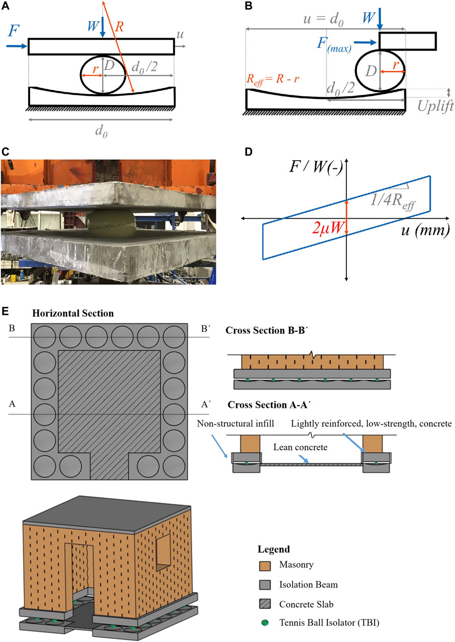
FIGURE 1. Spherical Deformable rolling isolator. (A) Under compression, (B) Under compression and lateral load, (C) During testing by Cilsalar and Constantinou (2019a); Cilsalar and Constantinou (2019b); Cilsalar and Constantinou (2019c), (D) Bilinear force-displacement plot, (E) Potential application of the tennis ball isolator (TBI) proposed in this study.
However, such a seismically isolated masonry dwelling still requires the use of a heavily reinforced slab at the isolation level. In an effort to reduce the thickness or completely eliminate the slab, many and closely spaced isolators can be used (Figure 1E). Then, each isolator should be of extremely low cost. To achieve this, instead of using elastomeric spheres, one can use tennis balls filled with cement paste. The concept is compatible with the concept of circular economy and re-using of materials. This paper presents a series of cyclic and compressive tests, which constitute a feasibility study of this idea.
Figure 1 shows the spherical deformable rolling seismic isolator that was proposed by Cilsalar and Constantinou (2019a), Cilsalar and Constantinou (2019b), Cilsalar and Constantinou (2019c). It comprises an elastomeric sphere rolling in between 2 concrete surfaces. It is essentially low cost version of the double concave friction pendulum bearing (Fenz and Constantinou 2006; Makris and Vassiliou 2011; Ponzo et al., 2015; 2021; Bao et al., 2017; Bao and Becker, 2019; Di Cesare et al., 2021 among others) that uses rolling instead of sliding.
Curved surfaces of different shapes and dimensions can be used. This paper examines 1) systems with one flat and one spherical rolling surface; and 2) systems where both concrete surfaces are flat, in order to understand the rolling behavior of the sphere.
A first approximation of the behavior of the proposed system can be obtained by assuming a rigid behavior for the rolling sphere (i.e., the mortar-filled tennis ball, in the case of this paper). Then the force-displacement relation is (Cilsalar and Constantinou, 2019a; Cilsalar H. and Constantinou, M. C. 2019; Cilsalar and Constantinou, 2019c):
where
The above rigid body approximation is convenient and elegant, but significantly deviates from the results of the tests performed by Cilsalar and Constantinou (2019a), Cilsalar and Constantinou (2019b), Cilsalar and Constantinou (2019c) apparently because of the deformability of the sphere.
Today’s tennis balls are made of a hollow, two-piece rubber shell filled with pressurized gas. The external diameter of the tennis balls should be between 65.4 and 68.6 mm, according to the specifications of the International Tennis Federation. The rubber shell of a tennis ball is covered with felt (made from nylon or wool), and has an approximate total thickness of 5 mm. The rubber part of the shell is made of two hemispheres that are pressed together. Subsequently, pressurized air is injected into the center of each rubber core, to achieve bounciness. The external surface of the pressurized rubber balls is then smoothened and covered in glue. Two different pieces of yellow felt are cut, wrapped around the tennis ball, and heated to glue together (Good, 2018).
For the tests, we obtained used tennis balls for free from tennis clubs that would have otherwise dumbed them. In fact, the waste created by tennis balls is a waste management issue on its own. Every year 300 million tennis balls are discarded globally. In the United States alone, 125 million tennis balls are sold every year, with most of them ending up in landfills (Miller, 2016). This is because, after each tennis game, the balls become softer and unsuitable for further use. No viable solution towards the mass-scale re-use and sustainable management of this large number of tennis balls is proposed so far, to the best of the authors’ knowledge.
Using tennis balls has a two-fold purpose: 1) It serves as a spherical mold to cast the cementitious paste, and, 2) The rubber shell reduces stress concentration at the contact area, increases the rolling resistance of the ball, and increases damping. So, the tennis balls are not removed after the cement paste cures.
Initially, mortar mixtures of cement, sand, and water were used to fill in the used tennis balls. The balls were cut in half, filled with mortar, and then stuck together with tape. The result was unsatisfactory, as the final shape deviated significantly from being spherical. Moreover, the two pieces of rubber were detached from the inner mortar core under cyclic loading. These tests are not discussed herein, but are mentioned as a failed strategy to discourage potential researchers and engineers from filling in the balls with this method.
Subsequently, instead of cutting the balls in half, a 15 mm-diameter hole was drilled in the balls to fill them with the mix, and improved cementitious mixtures were used. The external diameter of the balls was 67 mm. Hence, assuming a 5 mm shell, the inner diameter is 57 mm. Therefore, the mortar volume needed to fill a tennis ball isolator (TBI) is extremely small (less than 0.1 L) and the cost of the mixture does not govern; even the most expensive mixtures can be used because the total quantity to fill in enough tennis balls for a residential structure is very low.
A bag of 25 kg of conventional Portland CEM I 52.5 R cement costs approximately 10 $. Mixing this cement quantity with water, at a water to cement ratio W/C = 0.5, gives a mortar volume of 20 L. Therefore, one can cast 200 TBIs using the aforementioned mortar. This practically means that the cost of a single sphere is roughly 0.05 $ (excluding labor and assuming that the used balls are provided for free). The manufacturing time for each TBI is approximately 2 min. However, this is not the only cost of the system, as one would need to construct the concrete concave surfaces.
Initially, 7 different mixes were tested (Table 1), aiming at high strength, high fluidity (to allow for proper casting), and low shrinkage. In several cases, to ensure adequate fluidity, the used W/C was slightly higher than the one suggested by the manufacturers. Three variations for each mix were tested. 1) Using 3 orthogonal nails or 2) Using 3 orthogonal screws as reinforcement for the ball; 3) Using no reinforcement. The length and diameter of the used nails and screws were 45, 2.2 mm and 45, 4 mm, respectively. Three specimens of each variation were cast, resulting in a total of 3 × 3 × 7 = 63 TBIs. Four additional spheres of Mix 7 (without reinforcement) were cast, leading to a total number of 67 TBIs. The specimens were named MX-Y, where X denotes the mix number and Y is 0 for the specimens without reinforcement, N or S for the specimens with nails or screws, respectively.
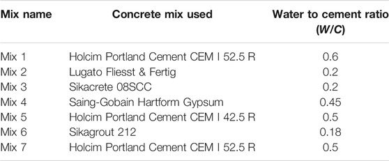
TABLE 1. Mixes used to fill the tennis balls.
Mix 1 and Mix 7 used the same cement (Holcim Portland Cement CEM I 52.5 R), with a water ratio (W/C) equal to 0.6 and 0.5, respectively. These two different W/C ratios were tested, trying to optimize strength and fluidity. Mix 2 was the commercial cementitious mix “Lugato Fliesst and Fertig”, which includes quarzitic and calzitic fillers together with organic additives and is typically used in floor leveling applications. Mix 3 was “Sikacrete-08SCC”, a self- compacting concrete mix, with a maximum aggregate size of 8 mm. A W/C = 0.2 was used, which is higher than the suggested 0.1 to ensure sufficient fluidity. Mix 4 was the only non-cementitious mix, employing “Saing-Gobain Hartform Gypsum” (Alpha plaster), with W/C = 0.45, which is slightly higher than the suggested 0.4. Using gypsum instead of concrete could allow for a shorter curing time, but one would also have to consider the possible effect of environmental factors (e.g., humidity) on the properties of gypsum. Mix 5 used Holcim Portland cement CEM I 42.5 R, which is similar to the one used in Mix 1 and 7, but of the lower class. Finally, Mix 6 was “Sikagrout 212”, a cementitious grout with selected fillers, aggregates, and additives and with W/C = 0.17, which is higher than the suggested 0.12.
A piping bag with a steel tip (usually used for cream pastries) was used to fill in the balls from the 15 mm hole to get more aggregates into the balls (Figure 2). During the pouring, the balls were shaken manually for compaction. Two days after the filling of the concrete balls, a gap near the casting holes of the tennis balls could be observed due to concrete shrinkage. To avoid this gap, the balls were topped up two days after casting.
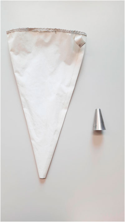
FIGURE 2. Left, Piping bag used to fill in the TBIs; Right, Steel tip attached to the piping bag.
Using a normal measuring cup (instead of a piping bag) to pure mortar into the balls is not recommended. This is because when using a measuring cup, the aggregates flow to the bottom, and the liquid part remains on top (the ingredients separate). Therefore, during pouring, mainly the liquid part ends into the sphere.
The balls were left to cure for 28 days, and then they were compressed between steel plates in a Universal Testing Machine at a compression rate of 2 mm/min. Before testing, spheres with visible casting flaws were excluded. This could be the first level of quality assurance in a practical application.
Figure 3 shows the force deformation diagrams of the compressive tests. The nail and screw reinforcement does not seem to increase the compressive strength of the balls, whereas they may impose additional casting difficulties. Therefore, this reinforcement strategy is not recommended. The large scatter of the results is attributed to casting imperfections and to the well-documented uncertainty of cementitious mixes, something that should be attempted to be improved in the future by using more workable mixes, potentially using admixtures.
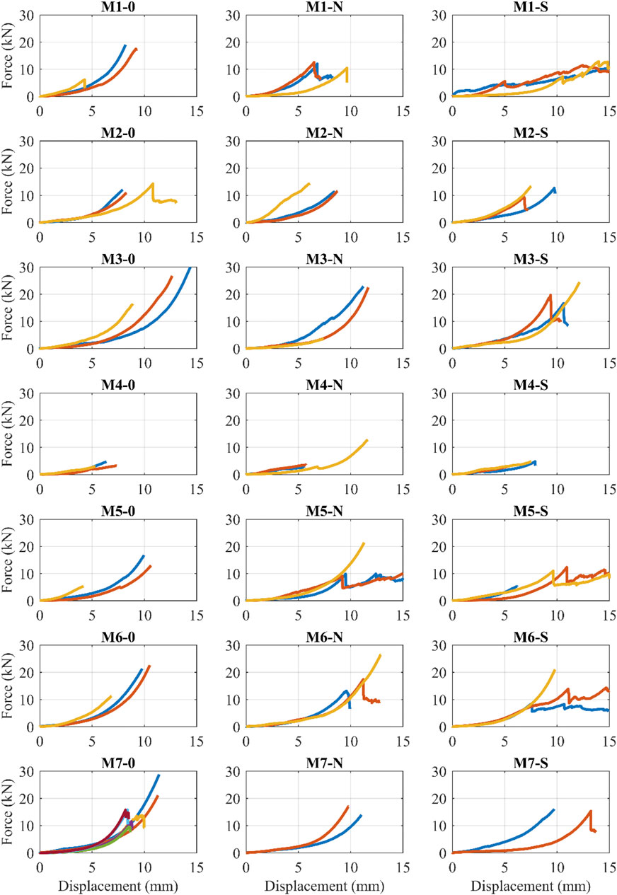
FIGURE 3. Compression tests of the TBI using different mixes, screws and nails.
Based on the tests, Mixes 3, 6 and 7 were chosen for further evaluation. It is worth noting that even the weakest (unreinforced) specimen of these mixes can sustain 10 kN of compressive load, which is more than two times higher than the design compressive force of a typical one-story masonry house in Cuba, as discussed in Tested Configurations and Testing Protocol of the Cyclic Tests.
The 1D shake table of the ETH (Bachmann et al., 1999) was used as an actuator to perform the cyclic tests. The shake table comprised a stiff steel box with dimensions of 2 × 1 m, excited by a 100 kN servo-hydraulic actuator. The stroke, maximum velocity, and maximum payload is ±120 mm, 220 mm/s, and 7.5 tons, respectively.
Figure 4A shows the experimental setup. An isolator consists of an upper concrete plate, a bottom concrete plate, and a mortar-filled tennis ball that rolls between them. In all configurations, the bottom concrete plate was flat. The top plate can be either concave (“Concave configuration”) or flat (“Flat configuration”).
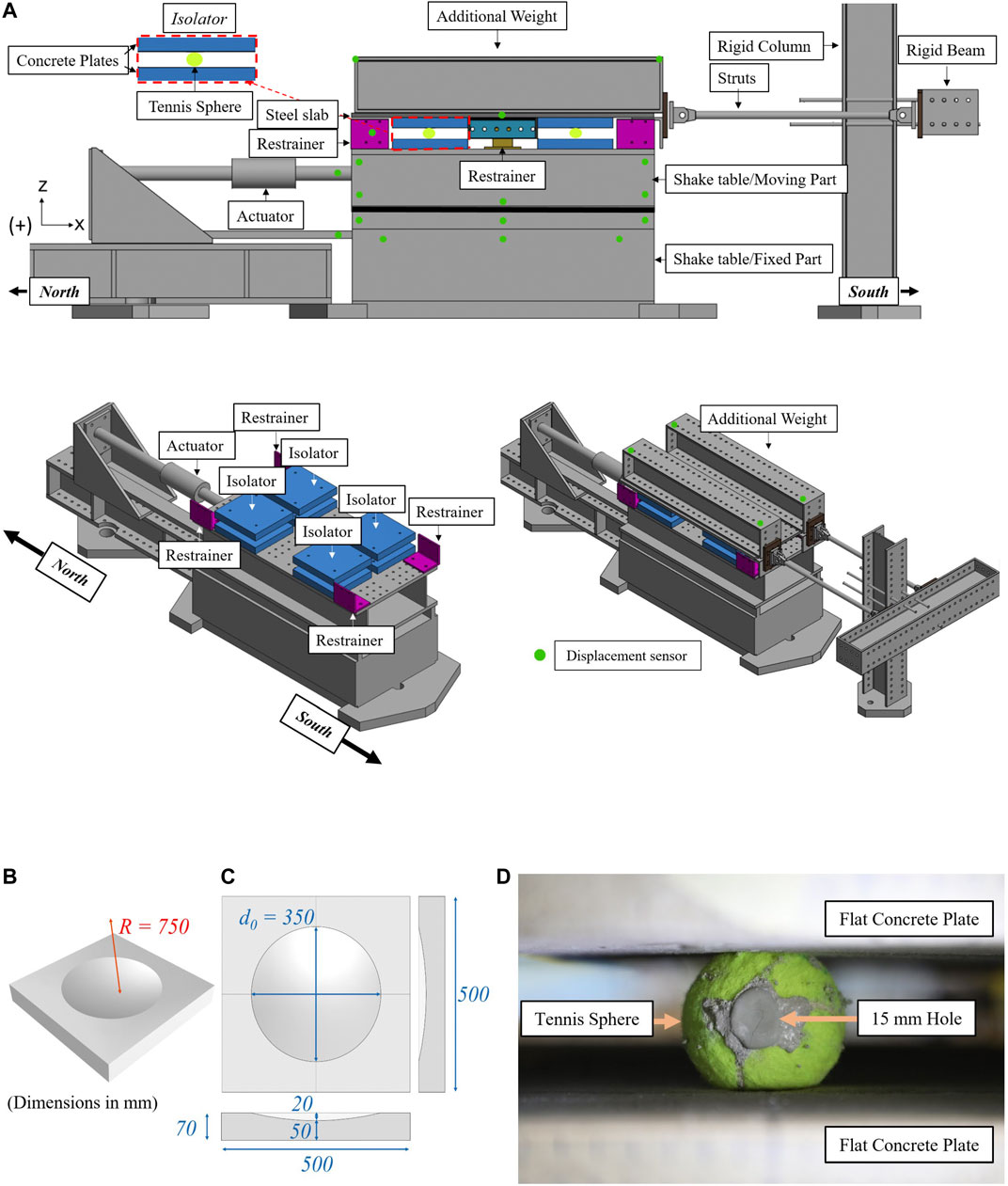
FIGURE 4. (A) Schematic representation of the utilized experimental setup. Green dots show the position of the displacement sensors. (B) 3D view of the concave concrete plates; (C) Plan and side view of the concave concrete plates; (D) TBI loaded with 3.23 kN of compressive force between flat concrete plates.
Four isolators (i.e., four pairs of concrete plates with a tennis ball in between) were placed on top of the shake table in a 2 by 2 configuration. The upper concrete plates of the isolators were mounted on a steel slab of 30 mm thickness. Variable weight, in the form of steel beams, was placed on top to emulate the weight of the structure. The bottom plates of the isolators were mounted on the surface of the shake table. A rail in the middle and side stoppers prevented the out-of-plane motion of the slab (i.e., motion along the y axis). To minimize friction, all stoppers and rails were covered with Teflon.
During the cyclic tests, the steel slab was constrained in the horizontal direction (x) by connecting it to a stiff column via two rigid struts. The struts also constrained the rotation around the vertical axis (z), and the shake table was used to impose the cyclic motion.
The lateral force imposed on the isolators during cyclic testing was measured with two strain gauges installed in the horizontal struts, which hold the steel diaphragm in place. The sampling frequency of the struts was 1,200 Hz.
The movement of the shake table and the superstructure was measured using an NDI Optotrak Certus system. A total of 22 infrared-emitting diodes markers were used to track all possible movements and rotations of the superstructure and the shake table (green dots in Figure 4A). The NDI system recorded the 3-dimensional position of the markers with an accuracy of 0.1 mm and a sampling frequency of 60 Hz.
A commercial low-cost M15 concrete mix was selected for the construction of the concrete plates, with a maximum aggregate size of 4 mm. The plates were unreinforced since steel reinforcement increases cost and construction time, making implementation harder in low-income countries. To minimize shrinkage cracking in a practical application, there should be a minimal reinforcement or fiber reinforcement. The plates were cast in wooden molds. The construction of the concave surfaces utilized plastic molds, carved in the desired dimensions (diameter of 350 mm in plan view, with a radius of curvature R = 750 mm, Figures 4B,C). After uncasting, the plates were covered with thin plastic sheets and left to cure for 28 days. It is worth noting that the plastic molds used for the concave surfaces were intact and reusable after uncasting. The average compressive and flexural strength of this concrete mix was equal to 27.62 MPa, and 4.63 MPa, respectively, tested according to EN 1015-11, (1993).
The tests are in full scale due to the evident impossibility of scaling tennis balls. In plan view, the diameter of the concave concrete plate was 350 mm (Figures 4B,C). The radius of curvature of the concave concrete plates (R) was R = 750 mm, which is similar to the bearings tested in Cilsalar and Constantinou (2019). Assuming a tennis ball diameter of Dt = 67 mm and based on Eq. 1 this would give an isolation period of
To calculate the compressive load that should be applied to each TBI, a typical modern unconfined masonry house in Cuba was considered. Typical masonry weighs 2.80 kN/m2. Assuming a wall height of 2.8 m, gives a weight of the masonry wall of 7.8 kN/m (without considering additional safety factors). A 10 cm roof slab at a typical 5 m × 5 m room would add 3 kN/m to each wall, giving a total weight of 11 kN/m. Assuming isolators placed every 0.40 m, the vertical load of each isolator is 0.4 × 11 kN = 4.4kN.
Four compressive loads (2.08, 3.23, 4.74, or 8 kN per sphere) under 2 rolling surface geometries (flat and concave) were planned. This corresponds to a total number of 8 configurations. However, due to a limitation of the experimental setup, the concave configuration under the maximum vertical load (8 kN) was not tested. Table 2 shows a summary of the tested configurations.
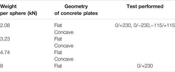
TABLE 2. Summary of the tested configurations.
A different set of 4 spheres was used in each weight/geometry configuration, resulting in 4 × 7 different spheres. Three different types of cyclic tests were performed for all configurations (apart from the one with W = 8 kN/sphere), with the following sequence: First, cyclic (“0/+230”) tests with the bottom slab applying a sinusoidal motion to the bottom concrete plate between zero and +230 mm (that is,
The excitation frequency of all cyclic tests was f = 0.2 Hz, corresponding to an average velocity of 92 mm/s.
As the specimens used for the rolling tests were coming from a new batch (not the one used for the initial compression tests of Compression Tests), more compressive tests were performed. The aim was to further quantify the dispersion of the strength, this time also among different persons building the specimens. The results are shown in Figure 5. It is evident that significant scatter exists even among the specimens of the same mix. The minimum compressive strength of the balls was 12.5 kN which is approximately 3 times higher than the expected (design) static vertical load of 4.4 kN. It is noted that for the vertical loads tested (2.08, 3.23, 4.74 and 8 kN per sphere) the corresponding vertical compressive displacement of the tennis spheres (excluding the sphere of Mix 6 with the largest displacements) is in the range of 4.5, 5, 5.8 and 6.8 mm, respectively. This means that the shape of the isolator deviates from being spherical, since the top and bottom end is flattened. Based on the results, the spheres of Mix 7 were selected for cyclic testing.
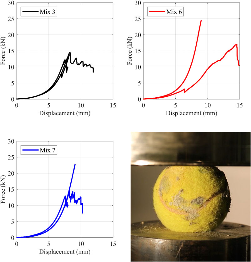
FIGURE 5. Compressive behavior of the three selected cementitious mixes. Top-Left, Mix 3; Top-Right, Mix 6; Bottom-Left, Mix 7; Bottom-Right, TBI under compression between steel plates.
The rolling friction coefficient (μroll) is defined as the ratio of lateral to vertical force at zero displacement. For all configurations, excluding the one with W = 8 kN, this coefficient is defined using the −115/+115 loop. For the configuration of W = 8 kN with flat plates, an approximate μroll is defined at 50 mm horizontal displacement, as no −115/+115 tests were performed with this configuration. Figures 6–11 (left) show the vertical displacement of the steel slab of the tests discussed in this paper as a function of the horizontal displacement. As imperfections cause small rotations of the slab around its horizontal axes, the vertical displacement is defined as the average of the vertical displacements, recorded by the 4 NDI infrared markers placed at its four corners above the isolators. Figures 6–11 (right) plot the ratio of lateral-to-vertical force against the lateral displacement.
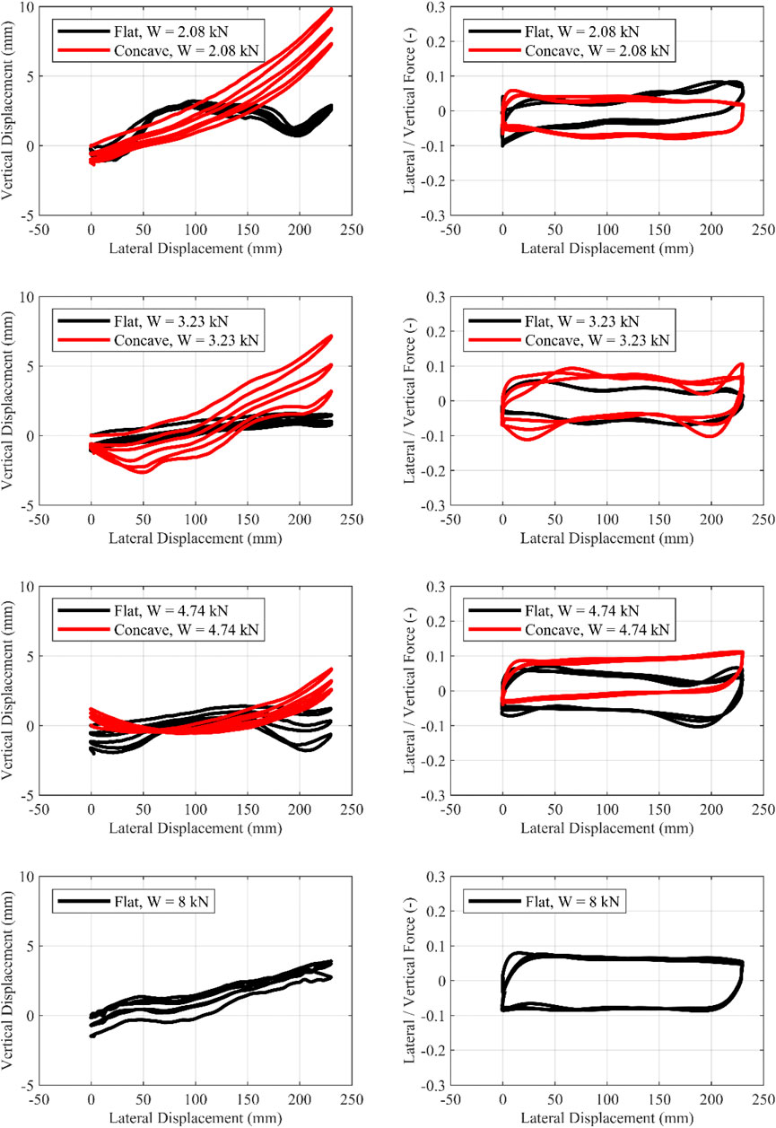
FIGURE 6. Cyclic motion 0/+230 mm. Influence of the geometry of the concrete plates. Left, Vertical-horizontal displacement; Right, Lateral/Vertical force—Lateral displacement.
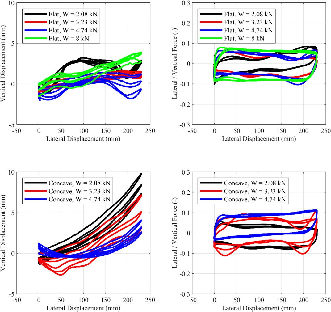
FIGURE 7. Cyclic motion 0/+230 mm. Influence of the vertical load. Left, Vertical-horizontal displacement; Right, Lateral/Vertical force—Lateral displacement.
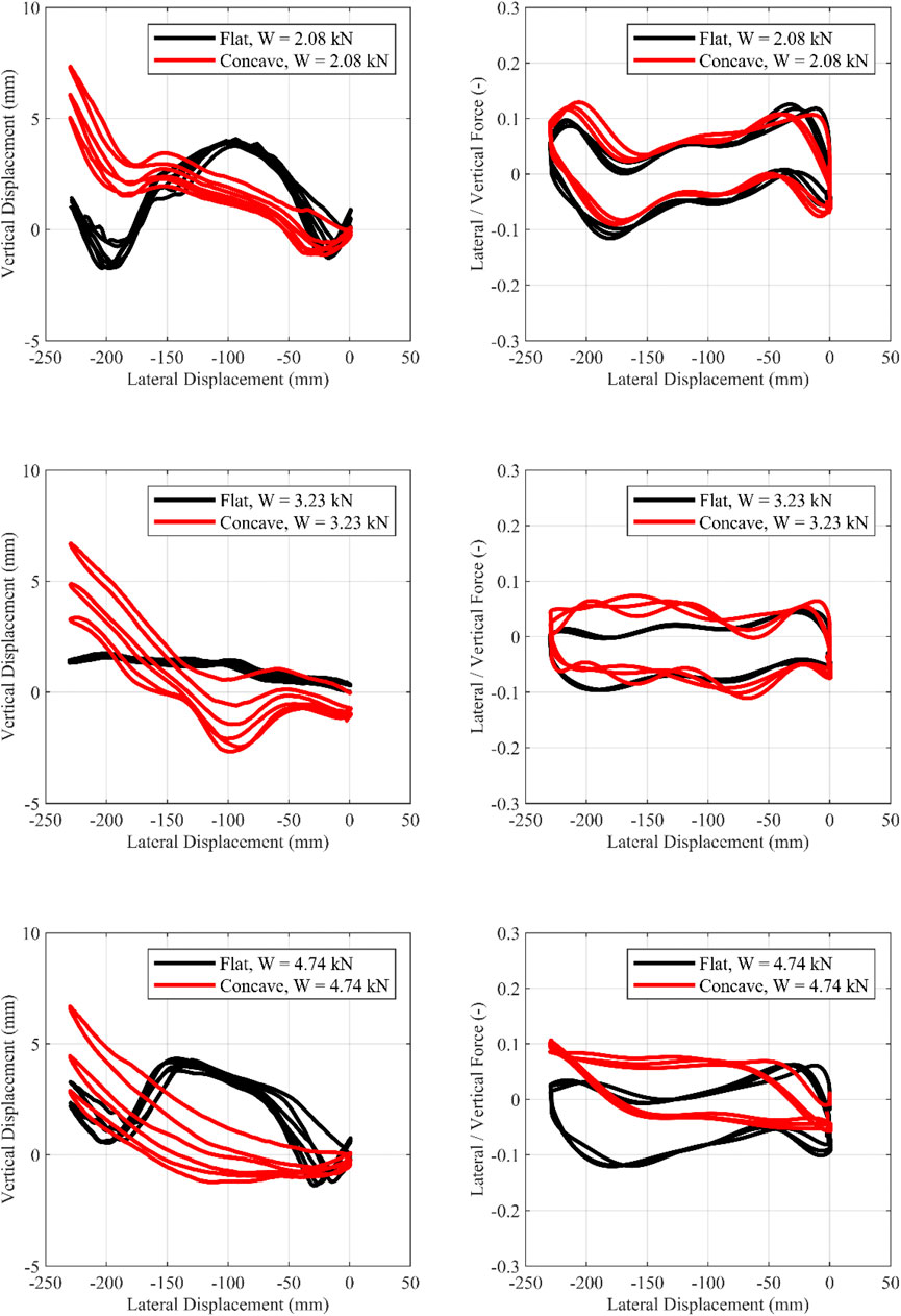
FIGURE 8. Cyclic motion from 0/−230 mm. Influence of the geometry of the concrete plates. Left, Vertical-horizontal displacement; Right, Lateral/Vertical force—Lateral displacement.
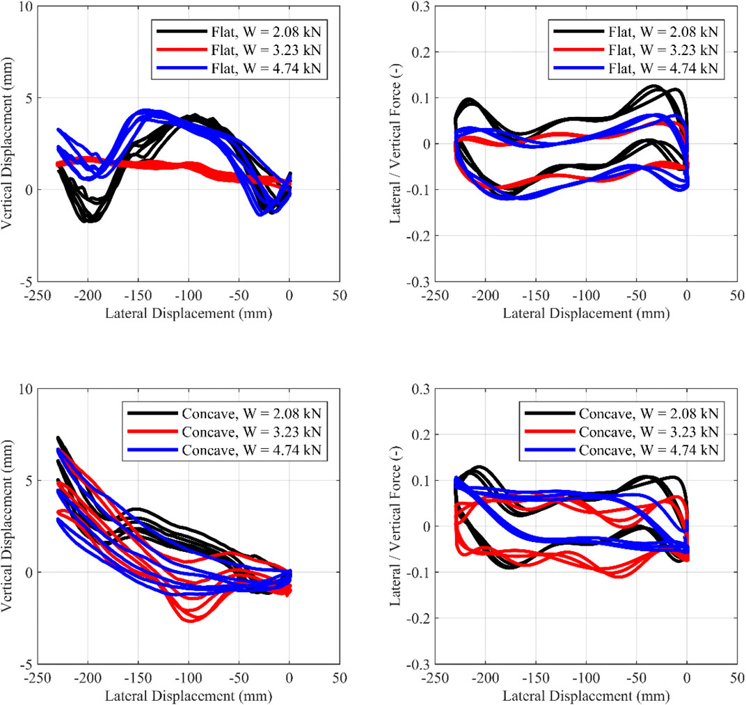
FIGURE 9. Cyclic motion 0/−230 mm. Influence of the vertical load. Left, Vertical-horizontal displacement; Right, Lateral/Vertical force—Lateral displacement.
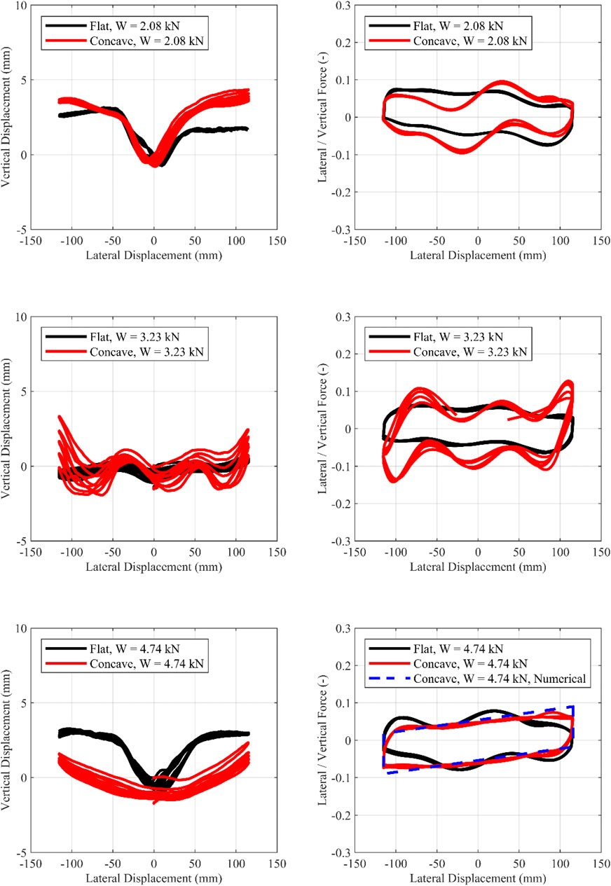
FIGURE 10. Cyclic motion ±115 mm. Influence of the geometry of the concrete plates. Left, Vertical-horizontal displacement; Right, Lateral/Vertical force—Lateral displacement.
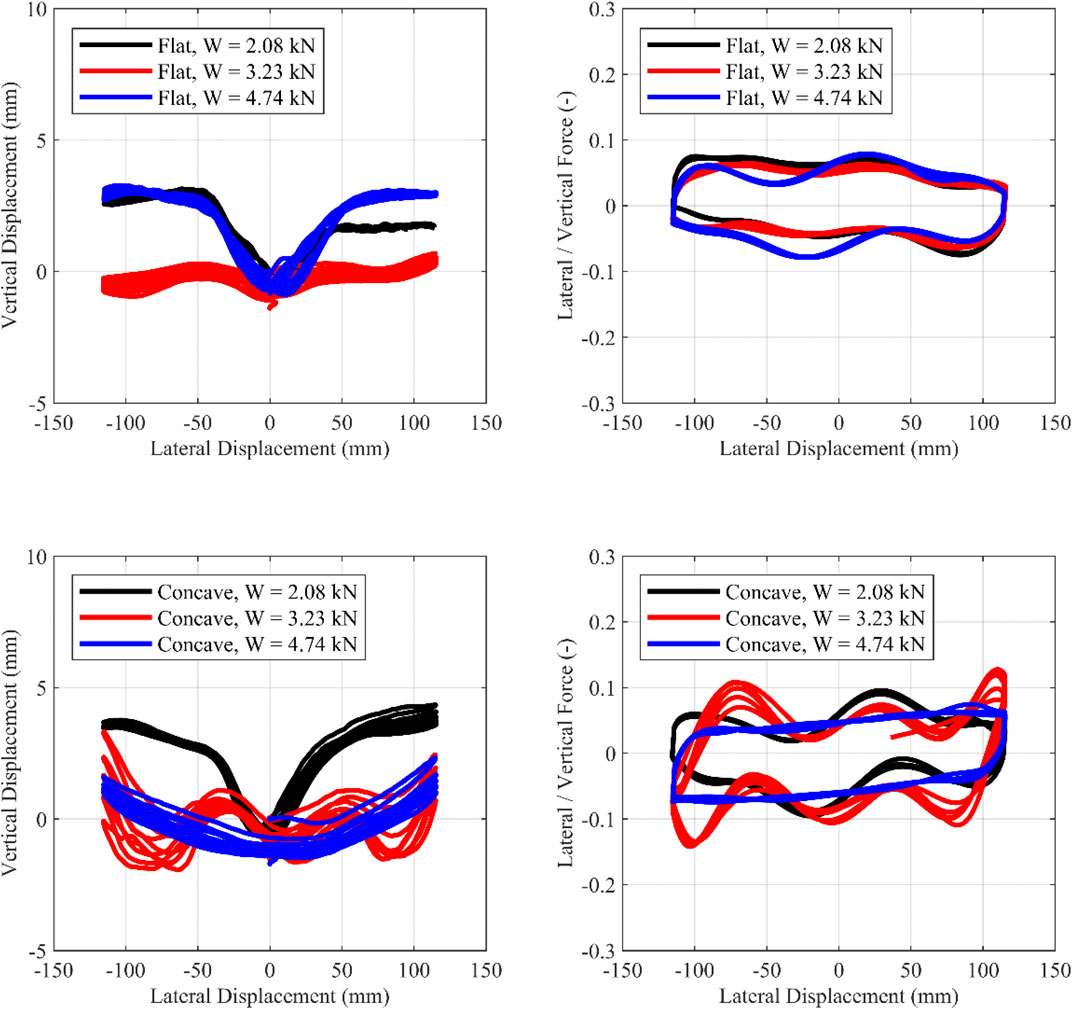
FIGURE 11. Cyclic motion ±115 mm. Influence of the vertical load. Left, Vertical-horizontal displacement; Right, Lateral/Vertical force—Lateral displacement.
Based on Figures 6–11, the following observations can be made:
1) Τhe curvature of the concrete plate influences the response moderately—for this chosen curvature that leads to a rather high isolation period of 3.4 s. The concave surface provides restoring force through gravity, with the restoring force being associated with the uplift of the upper slab of the isolator. For small lateral displacements (i.e., during the cyclic tests with an amplitude of ±115 mm), the effect of the concave plates is less pronounced since, according to the rigid body model, the corresponding uplift at maximum lateral displacement (115 mm) is 2.2 mm. Therefore, for small displacements, the local imperfections (due to compressive load or due to casting imperfections) of the TBI overshadow the uplift due to the concave plate. For the 0/+230 and 0/−230 tests, uplift at maximum lateral displacement (230 mm) is 9 mm. Thus, for larger lateral displacements (i.e., 0/+230 and 0/−230 motions), the influence of the plates becomes greater. These conclusions hold for the specific geometry of the concave concrete plates used in this study. Using a concave surface with a smaller radius of curvature (R) would lead to a more significant effect of geometry and should be tested in the future.
2) Two configurations (Concave 2.08 and 3.23 kN) demonstrated significant fluctuations, which were consistent over the cycles. These fluctuations are attributed to the insufficient casting (and shrinkage) of some of the spheres, which, during rolling, ended up with the flattened surface in contact with the concrete plates (Figure 12A). This led to intense vertical motion of the slab, affecting the restoring force and the force-displacement plot (Figure 10, middle-right, and Figure 11 bottom-right). Avoiding such imperfections in a practical application is crucial. It is interesting to note that significant fluctuations of the force-displacement loop also exist in other rolling systems, comprising seemingly “perfect” rolling objects, such as rubber wheels (Nikfar and Konstantinidis, 2017).
3) For the configurations of W = 4.74 kN/sphere (concave plates) and of W = 8 kN/sphere (flat plates), the response is very close to bilinear. The reason is that in these 2 configurations, the mortar core of the TBI remained totally intact during the test, without surface imperfections, as seen in Figure 12B,C. The configuration where W = 4.74 kN/sphere (concave plates) was used as a case study, to assess whether an analytical bilinear model can predict the experimentally obtained plot. This configuration was used since: 1) the spheres were properly cast and demonstated no surface imperfections and 2) concave plates are used, allowing for the use of Eq. 1. The effective radius of curvature Reff was set to 716.5 mm, following the equations of The Spherical Deformable Rolling Seismic Isolator. The rolling friction coefficient (μroll) was set to 5.4%, which is the experimentally obtained value (Table 3). It is noted that the value of μroll is not known a priori. The numerical results are closely correlated to the experimental ones for this configuration, indicating that, when casting is successful, the response of the isolator is indeed bilinear.
4) With the exception of the sphere used for the tests with the concave plates under W = 3.23 kN, the spheres deteriorated only marginally under cyclic loading. During rolling, one could hear a moderate cracking sound (mainly during the first circle) and see concrete dust. This is attributed to cracking of the mortar that was unavoidably accidentally spilled at the outer surface of the tennis ball while casting. The result was that, in some cases, the final vertical position of the steel slab was slightly lower than the initial one (settlement up to 2 mm). Even when settlements are observed, and even when 5 (or more) circles were applied, the cyclic loops remained stable. The consequences of the settlement to a masonry building remain to be quantified with system-level testing.
5) It is clear that there is energy dissipation that increases with increasing compressive load. Energy dissipation sources from the rolling resistance of the balls.
6) The friction coefficient (μroll, defined as the ratio of lateral-to-vertical force at zero displacement) ranges between 4.7 and 7.2% (Table 3) which is within the range of friction coefficients used in sliding bearings.
7) Even under W = 8 kN per sphere, no damage to the TBI was observed. This load level is significantly higher than the vertical design load of 4.4 kN and half of the average compressive strength of mix 7, which is 16.7 kN (Figure 5).
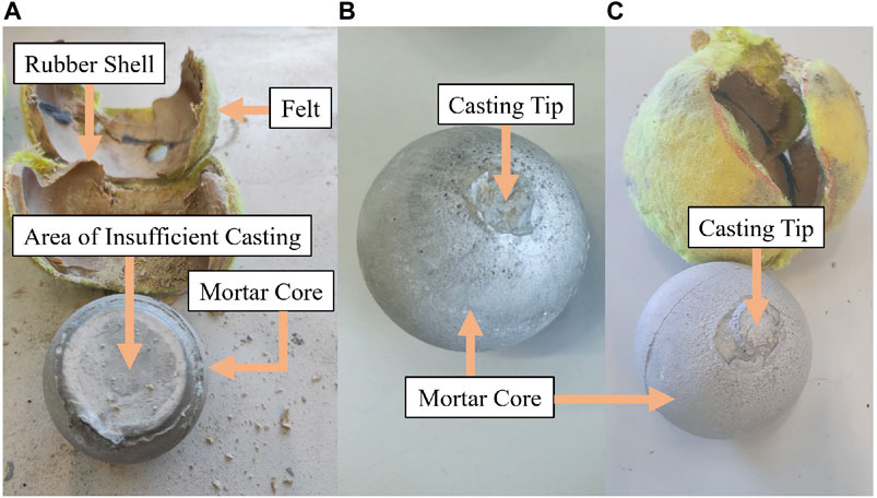
FIGURE 12. (A) TBI after 0/+230, 0/−230 and −115/+115 test under compressive force of W = 3.23 kN and concave concrete plates, (B) Tennis Ball Isolator (TBI) after 0/+230, 0/−230 and −115/+115 test under a compressive force of W = 4.74 kN and concave concrete plates, (C) Tennis Ball Isolator (TBI) after 0/+230 test under a compressive force of W = 8 kN and flat concrete plates.
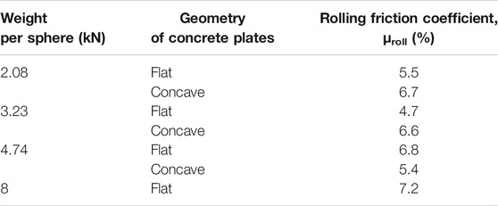
TABLE 3. Summary of the rolling friction coefficient μroll (%) for the various tested configurations.
This paper presents an experimental feasibility study on the compressive and cyclic response of low-cost bearings comprising mortar-filled tennis balls. The idea is to isolate masonry structures by placing the spheres at a dense grid so that only a thin or no diaphragm slab at the isolation level is required. Saving this cost is crucial to make seismic isolation affordable in low-income countries.
A full-scale model of prototype bearings was tested, comprising four isolators capped with a slab. The parameters of investigation of the cyclic tests were the vertical force on each rolling isolator (i.e., 2.08, 3.23, 4.74 or 8 kN) and the geometry of the rolling surface (i.e., flat or concave). The vertical loads were computed based on the assumption that the balls will be placed underneath the masonry walls (at a distance of 40 cm) of a typical one-story residential house in Cuba.
The experimental results showed that the investigated system has the potential to reduce the inertia forces transmitted to the superstructure, with the rolling friction coefficient (i.e., the ratio of lateral to vertical force at zero displacement) being in the range of 4.7%–7.2%, thus, suitable for seismic isolation applications. These values, the sufficient bearing capacity of the isolators under vertical load and the corresponding force-displacement loops, confirm the feasibility of the proposed isolator.
The experimental results proved that the casting quality influences the rolling surface of the proposed isolator and, thus, the force-displacement loop. When the isolators are properly cast, the resulting force-displacement loop is bilinear, as a rigid body model suggests.
Tennis balls are used as permanent molds, meaning that they are not removed after casting. This has 2 main advantages: 1) The rubber shell of the tennis ball offers increased energy dissipation, and, 2) Local damage at the contact area is avoided since the shell offers stress distribution. There is no information on the deterioration of the mechanical properties of the tennis balls when exposed to envirnonmental conditions, so further studies are needed on this subject. However, unlike rubber bearings, the isolation properties of the suggested device mainly source from its geometry. So any deterioration of the balls should be quantified but is not expected to be detrimental.
For the displacements and curvatures considered, the influence of the concrete plate curvature is moderate since, sphere imperfections dominate the response. Even in this case, the system maintains low lateral-to-vertical force ratios, suitable for seismic isolation applications. However, bearings of smaller radius of curvature (R) and smaller isolation period should be tested, so that a restoring force is guaranteed.
The proposed Tennis Ball Isolator (TBI) offers a promising alternative towards the re-use of tennis balls, which is an important environmental problem with no viable mass-scale solution so far.
The main limitations of the present study are related to the casting procedure of the TBI. The development of better cementitious mixes which will ensure fluidity, high strength, less shrinkage and better quality assurance, the optimization of the casting procedure (e.g., utilized tools, the diameter of the casting tip, etc.), component level testing under biaxial shear loading, design methods for the concrete plates, and system level testing are topics open to further research.
The raw data supporting the conclusions of this article will be made available by the authors, without undue reservation.
AK: methodology, writing-sections of the draft, data curation, testing. MC anc SE: testing. MV: conceptualization, methodology, writing-original draft, and supervision.
Support to the first and last author was provided by the European Research Council (ERC) under Starting Grant 803908. The methods, results, opinions, findings, and conclusions presented in this report are those of the authors and do not necessarily reflect the views of the funding agency.
The authors declare that the research was conducted in the absence of any commercial or financial relationships that could be construed as a potential conflict of interest.
All claims expressed in this article are solely those of the authors and do not necessarily represent those of their affiliated organizations, or those of the publisher, the editors and the reviewers. Any product that may be evaluated in this article, or claim that may be made by its manufacturer, is not guaranteed or endorsed by the publisher.
Bachmann, H., Wenk, T., Baumann, M., and Lestuzzi, P. (1999). Der Neue ETH-Erdbebensimulator. Schweizer Ingenieur und Architekt 4, 63–67. doi:10.3929/ethz-a-002068449
Bao, Y., Becker, T. C., and Hamaguchi, H. (2017). Failure of Double Friction Pendulum Bearings under Pulse-type Motions. Earthquake Engng Struct. Dyn. 46 (5), 715–732. doi:10.1002/eqe.2827
Bao, Y., and Becker, T. (2019). Three-dimensional Double Friction Pendulum Bearing Model Including Uplift and Impact Behavior: Formulation and Numerical Example. Eng. Structures 199, 109579. doi:10.1016/j.engstruct.2019.109579
Castillo Ruano, P., and Strauss, A. (2018). An Experimental Study on Unbonded Circular Fiber Reinforced Elastomeric Bearings. Eng. Structures 177, 72–84. doi:10.1016/j.engstruct.2018.09.062
Cilsalar, H., and Constantinou, M. C. (2019a). Behavior of a Spherical Deformable Rolling Seismic Isolator for Lightweight Residential Construction. Bull. Earthquake Eng. 17, 4321–4345. doi:10.1007/s10518-019-00626-z
Cilsalar, H., and Constantinou, M. C. (2019b). Development and Validation of a Seismic Isolation System for Lightweight Residential Construction, Technical Report MCEER-19-0001 University at Buffalo, Buffalo, NY, USA .
Cilsalar, H., and Constantinou, M. C. (2019c). Parametric Study of Seismic Collapse Performance of Lightweight Buildings with Spherical Deformable Rolling Isolation System. Bull. Earthquake Eng. 18, 1475–1498. doi:10.1007/s10518-019-00753-7
Cui, S., Bruneau, M., and Constantinou, M. C. (2012). Integrated Design Methodology for Isolated Floor Systems in Single-Degree-Of-Freedom Structural Fuse Systems, Technical Report MCEER-12-0004 University at Buffalo, Buffalo, NY, USA.
Das, A., Deb, S. K., and Dutta, A. (2016a). Comparison of Numerical and Experimental Seismic Responses of FREI-Supported Un-reinforced Brick Masonry Model Building. J. Earthquake Eng. 20 (8), 1239–1262. doi:10.1080/13632469.2016.1140098
Das, A., Deb, S. K., and Dutta, A. (2016b). Shake Table Testing of Un-reinforced brick Masonry Building Test Model Isolated by U-FREI. Earthquake Engng Struct. Dyn. 45 (2), 253–272. doi:10.1002/eqe.2626
de Raaf, M. G. P., Tait, M. J., and Toopchi-Nezhad, H. (2011). Stability of Fiber-Reinforced Elastomeric Bearings in an Unbonded Application. J. Compos. Mater. 45 (18), 1873–1884. doi:10.1177/0021998310388319
Di Cesare, A., Ponzo, F. C., and Telesca, A. (2021). Improving the Earthquake Resilience of Isolated Buildings with Double Concave Curved Surface Sliders. Eng. Structures 228, 111498. doi:10.1016/j.engstruct.2020.111498
EN 1015-11 (1993). “Methods of Test for Mortar for Masonry – Part 11: Determination of Flexural and Compressive Strength of Hardened Mortar”. Brussels: European Committee for Standardization, 1015.
Fenz, D. M., and Constantinou, M. C. (2006). Behaviour of the Double Concave Friction Pendulum Bearing. Earthquake Engng Struct. Dyn. 35 (11), 1403–1424. doi:10.1002/eqe.589
Foti, D., and Kelly, J. M. (1996). Experimental Analysis of a Reduced Scale Model Seismically Base Isolated with Rubber-Layer Roller Bearings (RLRB). Eur. Earthquake Eng. 10, 3–13.
Foti, D. (2019). Rolling Devices for Seismic Isolation of Lightweight Structures and Equipment. Design and Realization of a Prototype. Struct. Control. Health Monit. 26 (3), e2311. doi:10.1002/stc.2311
Good, L. (2018). What Are Tennis Balls Made Out of ? SportsRec. Available at: https://www.sportsrec.com/351180-what-are-basketballs-made-out-of.html (Accessed August 27, 2021).
Harvey, P. S., and Kelly, K. C. (2016). A Review of Rolling-type Seismic Isolation: Historical Development and Future Directions. Eng. Structures 125, 521–531. doi:10.1016/j.engstruct.2016.07.031
Jampole, E. A., Swensen, S. D., Fell, B., Miranda, E., and Deierlein, G. G. (2014). Dynamic Testing of a Low-Cost Sliding Isolation System for Light-Frame Residential Structures. 10NCEE.
Jampole, E., Deierlein, G., Miranda, E., Fell, B., Swensen, S., and Acevedo, C. (2016). Full-scale Dynamic Testing of a Sliding Seismically Isolated Unibody House. Earthquake Spectra 32 (4), 2245–2270. doi:10.1193/010616eqs003m
Kelly, J. M. (1999). Analysis of Fiber-Reinforced Elastomeric Isolators. J. Seismology Earthquake Eng. 2 (1), 19.
Kelly, J. M., and Calabrese, A. (2012). Mechanics of Fiber Reinforced Bearings. PEER Report 2012/101 .
Kelly, J. M., and Konstantinidis, D. (2011). Mechanics of Rubber Bearings for Seismic and Vibration Isolation. New Jersey, USA: John Wiley & Sons. doi:10.1002/9781119971870
Kelly, J. M. (2002). Seismic Isolation Systems for Developing Countries. Earthquake Spectra 18 (3), 385–406. doi:10.1193/1.1503339
Kelly, J. M., and Takhirov, S. M. (2001). Analytical and Experimental Study of Fiber-Reinforced Elastomeric Isolator. PEER Report 2001/11, Berkeley: Pacific Earthquake Engineering Research Center, University of California.
Konstantinidis, D., and Kelly, J. M. (2012). Two Low-Cost Seismic Isolation Systems. Proceedings of the 15th world conference on earthquake engineering, Lisbon, Portugul 24–28.
Makris, N., and Vassiliou, M. F. (2011). The Existence of 'complete Similarities' in the Response of Seismic Isolated Structures Subjected to Pulse-like Ground Motions and Their Implications in Analysis. Earthquake Engng. Struct. Dyn. 40 (10), 1103–1121. doi:10.1002/eqe.1072
Menga, N., Bottiglione, F., and Carbone, G. (2019). The Nonlinear Dynamic Behavior of a Rubber-Layer Roller Bearing (RLRB) for Vibration Isolation. J. Sound Vibration 463, 114952. doi:10.1016/j.jsv.2019.114952
Menga, N., Foti, D., and Carbone, G. (2017). Viscoelastic Frictional Properties of Rubber-Layer Roller Bearings (RLRB) Seismic Isolators. Meccanica 52 (11), 2807–2817. doi:10.1007/s11012-016-0612-y
Miller, S. (2016). Yellow, Fuzzy and Flat: Where Do Recycled Tennis Balls Go? The New York Times. Available at: https://www.nytimes.com/2016/09/11/sports/tennis/yellow-fuzzy-and-flat-where-do-recycled-tennis-balls-go.html (Accessed August 24, 2021).
Mordini, A., and Strauss, A. (2008). An Innovative Earthquake Isolation System Using Fibre Reinforced Rubber Bearings. Eng. structures 30 (10), 2739–2751. doi:10.1016/j.engstruct.2008.03.010
Nikfar, F., and Konstantinidis, D. (2017). Shake Table Investigation on the Seismic Performance of Hospital Equipment Supported on Wheels/casters. Earthquake Engng Struct. Dyn. 46, 243–266. doi:10.1002/eqe.2789
Norma Cubana NC46 (2017). Construcciones sismorresistentes — requisitos básicos para el diseño y construcción. Oficina Nacional de Normalización.
Osgooei, P. M., Tait, M. J., and Konstantinidis, D. (2014). Finite Element Analysis of Unbonded Square Fiber-Reinforced Elastomeric Isolators (FREIs) under Lateral Loading in Different Directions. Compos. Structures 113, 164–173. doi:10.1016/j.compstruct.2014.02.033
Osgooei, P. M., Tait, M. J., and Konstantinidis, D. (2017). Non-iterative Computational Model for Fiber-Reinforced Elastomeric Isolators. Eng. Structures 137, 245–255. doi:10.1016/j.engstruct.2017.01.056
Pauletta, M., Cortesia, A., Pitacco, I., and Russo, G. (2017). A New Bi-linear Constitutive Shear Relationship for Unbonded Fiber-Reinforced Elastomeric Isolators (U-FREIs). Compos. Structures 168, 725–738. doi:10.1016/j.compstruct.2017.02.065
Pauletta, M., Cortesia, A., and Russo, G. (2015). Roll-out Instability of Small Size Fiber-Reinforced Elastomeric Isolators in Unbonded Applications. Eng. Structures 102, 358–368. doi:10.1016/j.engstruct.2015.08.019
Pauletta, M., Di Luca, D., Russo, E., and Fumo, C. (2018). Seismic Rehabilitation of Cultural Heritage Masonry Buildings with Unbonded Fiber Reinforced Elastomeric Isolators (U-FREIs) - A Case of Study. J. Cult. Heritage 32, 84–97. doi:10.1016/j.culher.2017.09.015
Pauletta, M. (2019). Method to Design Fiber-Reinforced Elastomeric Isolators (U-FREIs) and Application. Eng. Structures 197, 109366. doi:10.1016/j.engstruct.2019.109366
Ponzo, F. C., Cesare, A. D., Leccese, G., and Nigro, D. (2015). Shaking Table Tests of a Base Isolated Structure with Double Concave Friction Pendulum Bearings. Bnzsee 48 (2), 136–144. doi:10.5459/bnzsee.48.2.136-144
Russo, G., Pauletta, M., and Cortesia, A. (2013). A Study on Experimental Shear Behavior of Fiber-Reinforced Elastomeric Isolators with Various Fiber Layouts, Elastomers and Aging Conditions. Eng. Structures 52, 422–433. doi:10.1016/j.engstruct.2013.02.034
Russo, G., Pauletta, M., Cortesia, A., and Dal Bianco, A. (2008). Experimental Behavior of Carbon Fiber Reinforced Isolators. AIP Conf. Proc. 1020 (1), 1467–1474. doi:10.1063/1.2963772
Russo, G., and Pauletta, M. (2013a). Sliding Instability of Fiber-Reinforced Elastomeric Isolators in Unbonded Applications. Eng. Structures 48, 70–80. doi:10.1016/j.engstruct.2012.08.031
Strauss, A., Apostolidi, E., Zimmermann, T., Gerhaher, U., and Dritsos, S. (2014). Experimental Investigations of Fiber and Steel Reinforced Elastomeric Bearings: Shear Modulus and Damping Coefficient. Eng. structures 75, 402–413. doi:10.1016/j.engstruct.2014.06.008
Swensen, S. (2014). Seismically Enhanced Light-Frame Residential Structures. Ph.D. Dissertation, California (US): Stanford University .
Thuyet, V. N., Deb, S. K., and Dutta, A. (2018). Mitigation of Seismic Vulnerability of Prototype Low-Rise Masonry Building Using U-FREIs. J. Perform. Constructed Facil. 32 (2), 04017136. doi:10.1061/(ASCE)CF.1943-5509.0001136
Toopchi‐Nezhad, H., Tait, M. J., and Drysdale, R. G. (2009). Shake Table Study on an Ordinary Low‐rise Building Seismically Isolated with SU‐FREIs (Stable Unbonded‐fiber Reinforced Elastomeric Isolators). Earthquake Eng. Struct. Dyn. 38 (11), 1335–1357. doi:10.1002/eqe.923
Toopchi-Nezhad, H., Tait, M. J., and Drysdale, R. G. (2008a). Lateral Response Evaluation of Fiber-Reinforced Neoprene Seismic Isolators Utilized in an Unbonded Application. J. Struct. Eng. 134 (10), 1627–1637. doi:10.1061/(asce)0733-9445(2008)134:10(1627)
Toopchi-Nezhad, H., Tait, M. J., and Drysdale, R. G. (2008b). Testing and Modeling of Square Carbon Fiber‐reinforced Elastomeric Seismic Isolators. Struct. Control. Health Monit. 15 (6), 876–900. doi:10.1002/stc.225
Tran, C., Calabrese, A., Vassiliou, M. F., and Galano, S. (2020). A Simple Strategy to Tune the Lateral Response of Unbonded Fiber Reinforced Elastomeric Isolators (FREIs). Eng. Structures 222, 111128. doi:10.1016/j.engstruct.2020.111128
Tsiavos, A., Alexander, N. A., Diambra, A., Ibraim, E., Vardanega, P. J., Gonzalez-Buelga, A., et al. (2019). A Sand-Rubber Deformable Granular Layer as a Low-Cost Seismic Isolation Strategy in Developing Countries: Experimental Investigation. Soil Dyn. Earthquake Eng. 125, 105731. doi:10.1016/j.soildyn.2019.105731
Tsiavos, A., Haladij, P., Sextos, A., and Alexander, N. A. (2020a). Analytical Investigation of the Effect of a Deformable Sliding Layer on the Dynamic Response of Seismically Isolated Structures. Structures 27, 2426–2436. doi:10.1016/j.istruc.2020.08.016
Tsiavos, A., Sextos, A., Stavridis, A., Dietz, M., Dihoru, L., and Alexander, N. A. (2020b). Large-scale Experimental Investigation of a Low-Cost PVC 'sand-Wich' (PVC-S) Seismic Isolation for Developing Countries. Earthquake Spectra 36 (4), 1886–1911. doi:10.1177/8755293020935149
Tsiavos, A., Sextos, A., Stavridis, A., Dietz, M., Dihoru, L., Di Michele, F., et al. (2021). Low-cost Hybrid Design of Masonry Structures for Developing Countries: Shaking Table Tests. Soil Dyn. Earthquake Eng. 146, 106675. doi:10.1016/j.soildyn.2021.106675
Van Engelen, N. C., Konstantinidis, D., and Tait, M. J. (2016). Structural and Nonstructural Performance of a Seismically Isolated Building Using Stable Unbonded Fiber-Reinforced Elastomeric Isolators. Earthquake Engng Struct. Dyn. 45 (3), 421–439. doi:10.1002/eqe.2665
Van Engelen, N. C., Osgooei, P. M., Tait, M. J., and Konstantinidis, D. (2014b). Experimental and Finite Element Study on the Compression Properties of Modified Rectangular Fiber-Reinforced Elastomeric Isolators (MR-FREIs). Eng. Structures 74, 52–64. doi:10.1016/j.engstruct.2014.04.046
Van Engelen, N. C., Tait, M. J., and Konstantinidis, D. (2015). Model of the Shear Behavior of Unbonded Fiber-Reinforced Elastomeric Isolators. J. Struct. Eng. 141 (7), 04014169. doi:10.1061/(asce)st.1943-541x.0001120
Keywords: seismic isolation, rolling bearings, low-cost seismic isolation, sustainable construction, re-use
Citation: Katsamakas AA, Chollet M, Eyyi S and Vassiliou MF (2021) Feasibility Study on Re-Using Tennis Balls as Seismic Isolation Bearings. Front. Built Environ. 7:768303. doi: 10.3389/fbuil.2021.768303
Received: 31 August 2021; Accepted: 14 September 2021;
Published: 30 September 2021.
Edited by:
Luigi Di Sarno, University of Liverpool, United KingdomReviewed by:
Paolo Castaldo, Politecnico di Torino, ItalyCopyright © 2021 Katsamakas, Chollet, Eyyi and Vassiliou. This is an open-access article distributed under the terms of the Creative Commons Attribution License (CC BY). The use, distribution or reproduction in other forums is permitted, provided the original author(s) and the copyright owner(s) are credited and that the original publication in this journal is cited, in accordance with accepted academic practice. No use, distribution or reproduction is permitted which does not comply with these terms.
*Correspondence: Michalis F. Vassiliou, dmFzc2lsaW91QGliay5iYXVnLmV0aHouY2g=
Disclaimer: All claims expressed in this article are solely those of the authors and do not necessarily represent those of their affiliated organizations, or those of the publisher, the editors and the reviewers. Any product that may be evaluated in this article or claim that may be made by its manufacturer is not guaranteed or endorsed by the publisher.
Research integrity at Frontiers
Learn more about the work of our research integrity team to safeguard the quality of each article we publish.