 Michele Palermo
 Vittoria Laghi
 Giada Gasparini
 Stefano Silvestri
 Tomaso Trombetti
- Department of Civil, Chemical, Environmental and Materials Engineering, University of Bologna, Bologna, Italy
The paper investigates the dynamic behavior of structural systems obtained by connecting a moment-resisting frame structure with a vertical rigid truss pinned at the base, known in literature as “strongback,” and equipped with added fluid-viscous dampers. The strongback, designed in order to remain in the elastic field under strong seismic ground motion, acts as a mast by imposing to the structure a linear lateral deformed shape. By regularizing the lateral drift profile of the structure, the strongback limits undesired effects such as weak-storey mechanisms, damage concentration and residual drifts. In addition, when supplemental dampers are inserted in the structure, a considerable amount of energy can be dissipated, thus reducing the peak seismic response. The aim of the work is twofold: i) to provide analytical formulations for the preliminary design of added dampers based on the Generalized Single Degree Of Freedom (GSDOF) concept, and ii) to evaluate the increase in energy dissipation capabilities for selected dampers configurations thanks to the presence of the strongback. The formulas are developed for different configurations of added viscous dampers: dampers inserted within the frame between all or selected consecutive storeys (inter-storey placement) and dampers located at the base of the strongback to realize a rigid “dissipative tower.” The effectiveness of the dampers configurations is evaluated through dynamic time-history analyses.
Introduction
Traditional steel frame structures have typically limited resistance towards seismic events, with the tendency to form soft- and weak-storey mechanisms, damage concentration, P-Δ effects and residual drifts. These issues can be particularly relevant for conventional concentrically-braced frames (Khatib et al., 1988; Rai and Goel 1997; Sabelli 2001; Tremblay 2003; Hines and Appel 2007; Uriz and Mahin 2008; Hines et al., 2009; Lai et al., 2010; Chen and Mahin 2012).
In order to mitigate such undesired effects, some specific considerations during the design phase of frame structures should be made following the Performance-Based Seismic Design (PBSD) approach (Bertero and Bertero 2002) together with the adoption of new technological solutions. Among others, possible solutions are represented by the use of enhanced dissipative braces such as: steel bracing systems (Foutch et al., 1987; Whittaker et al., 1990), buckling-restrained braces and zippers (Khatib et al., 1988; Tirca and Tremblay 2004; Kiggins and Uang 2006, Yang et al., 2008; Yang et al., 2009; Yang et al., 2010; Stavridis and Shing 2010), rocking or uplifting systems (Clough and Huckelbridge 1977; Kelly and Tsztoo 1977; Uriz and Mahin 2008; Deierlein et al., 2011), viscous dampers (Constantinou et al., 1998; Christopoulos and Filiatrault 2006; Silvestri et al., 2010; Castaldo and De Iuliis 2014; Palermo et al., 2018), hysteretic devices (Trombetti et al., 2004; Palermo et al., 2014; Palermo et al., 2015) or shear links (Nuzzo et al., 2018).
An alternative solution is to couple the frame system with strong rocking walls, able to reduce the damage concentration in the frame, as well as to uniform the deformed shape under seismic action, thus reducing the concentration of drifts in the lower storeys (Alavi and Krawinkler 2004). Analytical and numerical studies have been proposed by several researchers to investigate the seismic behavior of strong rocking wall-frame systems, consisting of an external rigid wall pinned at the base and rigidly connected at each floor to the frame (Qu et al., 2011; Wu et al., 2016). Qu et al. (2012) proposed a dissipative solution combined to strong rocking walls through horizontal yielding dampers able to dissipate the seismic-induced energy through the relative vertical displacement between the frame and the wall at each floor level. Analytical formulations of the wall-frame-damper system considered as a continuous model were proposed in Sun et al. (2018). Pan et al. (2018) proposed the use of infill rocking wall-frame systems to reduce damage concentration of frame structures subjected to seismic action. Their effectiveness has been verified through quasi-static cyclic tests on a prototype structure. The same system has also been studied in Wu et al. (2017) with specific focus on its reparability after damage. Wang et al. (2018) studied the seismic response of infill rocking walls equipped with yielding dampers at the base, referred to as plastic-hinge-supported wall system.
The insertion of viscous dampers at the base of an external pinned rigid truss structure was proposed (Roia et al., 2013) and patented as the “dissipative tower” concept. A further work by Gioiella et al. (2018) investigated the dynamic behavior of such structural solution by means of complex damping theory and provided a case-study application. The results proved that the solution is effective in terms of energy dissipation.
A concept similar to strong rocking walls was proposed by Lai and Mahin (2014) and referred to as “strongback system.” In detail, the first idea has been developed as a rigid steel bracing within the frame structure, to avoid weak- and soft-storey mechanisms and thus reduce the concentration of damage induced by seismic action in the first storeys. Numerical and experimental studies on the same system have been developed by Simpson and Mahin (2018) and further implemented in the work done by Toorani (2020). Palermo et al. (2018a) adapted the same idea on an external pinned-based rigid steel braced truss structure linked to the frame at each floor and investigated the coupled static behaviour of a frame structure connected to this external strongback system. The aim of the work was to obtain expressions of the mutual actions exchanged between the frame and the external strongback system. The results indicated that both the distribution and the amplitude of such mutual actions are strongly influenced by the beam-to-column stiffness ratio. In particular, in case of flexible beams, large mutual actions and internal frame forces concentrate in the lower storeys, while the upper storeys remain practically unloaded.
In this paper, the dynamic behavior of frames connected to an external strongback (SB) system and equipped with different configurations of supplemental viscous dampers is investigated. In addition to the dissipative tower configuration, another configuration of added viscus dampers is considered, namely viscous dampers inserted within two consecutive storeys of the frame (inter-storey placement). In detail, different configurations of inter-storey viscous dampers are studied, either at all storeys or only at selected ones. The aims are i) to provide analytical formulations for the preliminary design of the added dampers, based on the Generalized Single Degree Of Freedom (GSDOF) approach recently discussed in the work by Palermo et al. (2020), and ii) to evaluate the increase of energy dissipation capabilities for the considered dampers configurations due to the presence of the strongback. Indeed, the presence of the rigid strongback, which imposes a linear lateral deformed shape, is expected to induce a more uniform along-the-height energy dissipation, especially for non-uniform dampers configurations.
Problem Formulation and Objective
Since the aim of the study is to investigate the fundamental dynamic properties of frame structures connected to a strongback and equipped with supplemental viscous dampers, simplified idealized systems are here considered, similarly to the ones considered in the work by Palermo et al. (2018) and Palermo et al. (2020). Henceforth, the term “system” will be used to indicate the frame connected to the external strongback and equipped with supplemental dampers. For this specific purpose, it is convenient to idealize the strongback as an external rigid truss pinned at the base and connected to the adjacent frame through horizontal rigid trusses (Figure 1A). It is assumed that the strongback is composed by rigid elements so that it rotates around the pinned base as a rigid body.
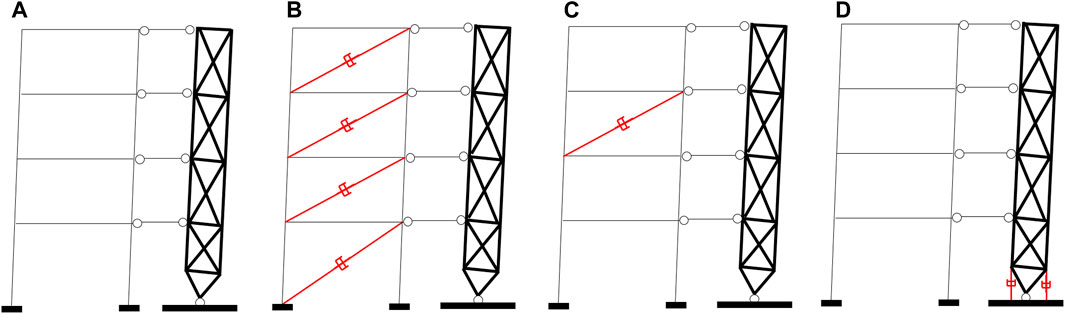
FIGURE 1. Different configurations of frames connected to an external strongback: (A) bare frame; (B) SPD system; (C) IS system; (D) DT system.
Various configurations of supplemental viscous dampers are here investigated: i) diagonal viscous dampers inserted within the frame between all consecutive storeys with damping coefficients proportional to the storey’s lateral stiffnesses (Figure 1B), thus resulting in a Stiffness Proportional Damping (SPD) system (Trombetti and Silvestri 2004), ii) diagonal viscous dampers inserted within the frame in a unique floor, according to the so-called Inter-Storey damper placement (Figure 1C, such system will be referred to as IS system); iii) viscous dampers placed at the base of the strongback to realize the so-called rigid Dissipative Tower (Figure 1D, such system will be referred to as DT system). As previously mentioned, for the IS system the presence of the rigid strongback should be capable of enhancing the dissipative properties of the damping system with respect to the corresponding systems without the strongback, that are characterized by quite reduced effectiveness (Palermo et al., 2020). In a DT system, the two viscous dampers located at the base of the strongback dissipate energy through a couple of damping forces acting along the vertical direction. The vertical velocity of the dampers can be determined from the rigid rotation of the strongback, as it will be clarified in the next section.
In this work, all added viscous dampers are assumed to have a linear force-velocity constitutive behavior and to be supported by infinitely stiff braces. Regarding these two assumptions, for design purposes, the following observations are made. It is common practice to first define the size of the dampers through a linear model, and then identify the non-linear mechanical properties of commercial manufactured dampers by means of specific energetic criteria (Christopoulos and Filiatrault 2006; Silvestri et al., 2010; Palermo et al., 2018). Similarly, the stiffness of the elastic brace connecting the viscous damper to the structure should be properly designed (Silvestri et al., 2010) to avoid detrimental effects (Castaldo and De Iuliis 2014).
As illustrated in Figure 2, the geometrical configuration of frames connected to the strongback can be described by assuming a system of coordinates (x, z) with origin at the base of the strongback (namely point O in Figure 2). The i-th storey is located at a height zi. The lateral displacement of the i-th floor is indicated with ui. It is assumed that the frame elements have a linear elastic behavior. The lateral stiffness of the i-th storey is denoted as ki. The axial deformability of the frame members is neglected. Shear-type frames are considered. The kinematics of the strongback is completely described by the angle of rotation θ. According to these assumptions, when subjected to a generic set of external lateral forces, the system will globally develop a linear lateral floor displacement profile. The linear deformed shape of the frame is guaranteed by mutual actions Hi which are exerted between the frame and the strongback. In the work by Palermo et al. (2018b), analytical expressions of the mutual actions were derived for different frame behaviors (namely moment resisting shear-type frames and hinged frames), different distributions of static external forces and storey lateral stiffnesses ki.
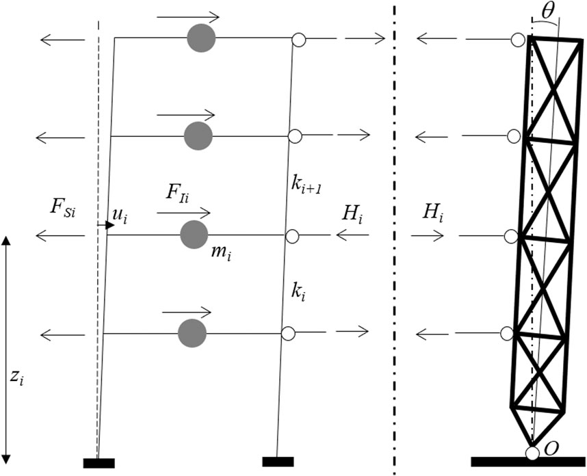
FIGURE 2. Dynamic forces acting on the undamped frame and on the strongback.
Under the above assumptions, from a global dynamic equilibrium perspective, the system can be rigorously treated, without introducing approximations, as a GSDOF system (Chopra 2001; Palermo et al., 2020), since its motion is governed and fully described by the rigid rotation angle of the strongback.
In the next sections, the dynamic behavior of the different damped systems with strongback is investigated with the purpose of determining their fundamental dynamic properties (natural frequency and damping ratio), their dissipative properties and their performances under earthquake excitation in comparison to systems without strongback.
Dynamic Equilibrium of Undamped and Damped Frames Connected to a Strongback
The Undamped System
In the present section, the attention is focused on the undamped system, namely the system without added dampers. In free vibration conditions, according to D’Alembert’s principle (Chopra 2001), the dynamic system is in equilibrium, at each time instant, under the following dynamic actions: the inertia forces FI,i, the elastic resisting forces FS,i, and the mutual actions Hi (i indicates the generic i-th storey). Figure 2 displays the system cut vertically along the connections between the frame and the strongback to evidence these mutual forces.
As demonstrated in the work by Palermo et al. (2020), the dynamic equilibrium of a generic (either undamped or damped) system can be studied by introducing two different GSDOF system, namely a translational GSDOF (derived by imposing the global translational equilibrium, referred to as Generalized Translational Oscillator–GTO) and a rotational GSDOF (obtained by imposing the global rotational equilibrium at the base, referred to as Generalized Rotational Oscillator–GRO). The approach requires an assumed deformed shape vector d representative of a given mode shape. However, when the system is connected to a rigid strongback, the shape of the lateral deformed shape is known and defined by a linear vector d. In this case, as demonstrated in the work by Palermo et al. (2020), the two GSDOF systems are characterized by the same fundamental dynamic properties, e.g. period of vibration and damping ratio (see Supplementary Appendix S1).
Henceforth, for the specific case of an undamped frame structure connected to a strongback, only the global rotational equilibrium equations of the frame and of the strongback (see Figure 2) will be considered:
where:
and
Since the third term of Eq. 1a is null due to Eq. 1b, 1a can be rearranged as follows:
Considering a uniform inter-storey height equal to h, then the inter-storey drift is also uniform and equal to δ. In this case, the i-th floor height zi and the lateral displacement ui can be expressed as follows:
Substitution of Eq. 6 in Eq. 4 leads to:
Eq. 7 represents the equation of motion of the GSDOF system in the generalized coordinate δ. The same equation can be also expressed in compact notation or, alternatively, in matrix notation (m representing the mass matrix and k the stiffness matrix) using the angle θ (θ=δ/h) as the degree of freedom (Palermo et al., 2020):
where z is the vector that groups the coordinates zi of the different floors.
The expressions of the generalized mass M*, generalized stiffness K* and circular frequency
The Damped Systems
In the present section, the attention is focused on a frame connected to the strongback and equipped with a generic damping system, for instance with either a SPD, an IS or a DT system. In the general case, the dynamic equilibrium of the whole system can be formulated using the same approach as the one adopted for the undamped case, but including also the contribution of the damping forces. The damping system can be characterized by the damping matrix c. By doing so, the following global dynamic rotational equilibrium equation governs the behavior of the frame structure:
Alternatively, in the case of uniform inter-storey height h:
The expression of the generalized damping coefficient C* depends on the specific configuration of the damping system. The expression of C* for the case of the SPD and IS damping systems (without the strongback) were derived in the work by Palermo et al. (2020), for both cases of a generic deformed shape and a linear deformed shape. The latter corresponds to the case of a frame connected with a strongback.
The dynamic behavior of the DT damping system is here investigated in detail (Figure 3) with the purpose of deriving the corresponding dynamic equation of motion. In this case, the energy is dissipated through the forces exerted by the two viscous dampers located at the base of the strongback. Each damper has a damping coefficient equal to cDT and acts along the vertical direction. From simple geometrical considerations (see Figure 3), the vertical displacement v of each damper can be related to the strongback rigid rotation θ (or, similarly, to the first inter-storey drift δ1) through the following relationship:
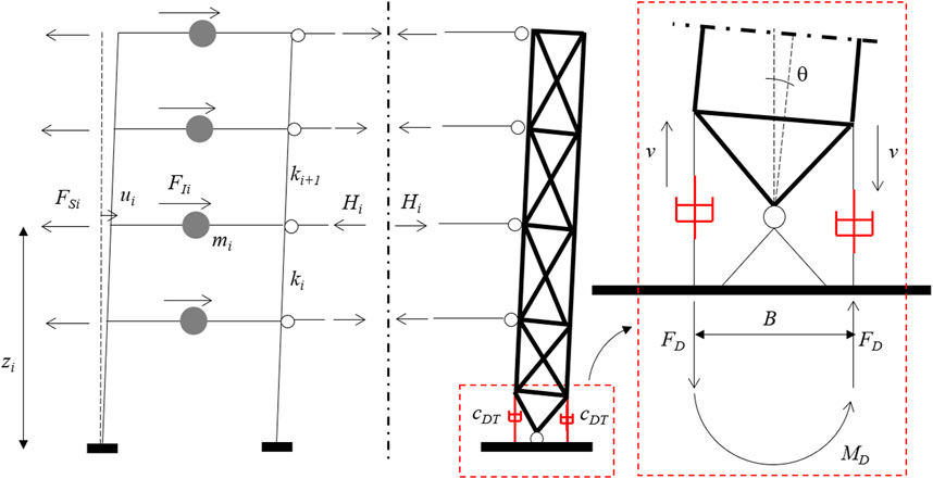
FIGURE 3. Dynamic forces acting on the DT system.
By indicating with
The couple of damping forces FD produces a dissipative bending moment MD equal to:
The whole system is globally in equilibrium if the following system of rotational equilibrium equations is satisfied:
Substituting Eq. 15b and Eq. 14 in Eq. 15a leads to the following expression of the global equilibrium equation of the frame:
Considering a uniform inter-storey height h, then the first inter-storey drift δ1 is equal to δ. Substituting Eq. 5 and Eq. 6 in Eq. 16 leads to the following equation of motion of the DT damped system:
By comparing Eq. 17 with Eq. 11 it is clear that the expression of the generalized damping coefficient for the DT system results equal to
Equivalent Damping Ratio for the Different Damped Systems
Since Eq. 11 and Eq. 17 represent the equations of motion of damped GSDOF systems in the degree of freedom δ, from fundamentals of structural dynamics it is possible to obtain the relationships relating the equivalent damping ratio with the damping coefficients. Table 1 summarizes these expressions for the different damped systems considered in the present study, considering both a generic frame and a uniform frame, namely a frame with uniform storey height h, uniform distribution of floor mass m and storey stiffness k and with dampers having the same damping coefficient c. The analytical expressions are based on an assumed linear lateral deformed shape.
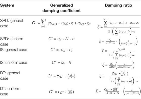
TABLE 1. Damping coefficients and damping ratios in the general case and for the uniform systems.
The analytical expressions of the equivalent damping ratios collected in Table 1 allow to compare the effectiveness of the different damped systems in terms of energy dissipation capabilities. For this purpose, it is useful to evaluate the total damping coefficient ctot =
Firstly, it can be noted that the expressions for
Figure 4A displays the trends of
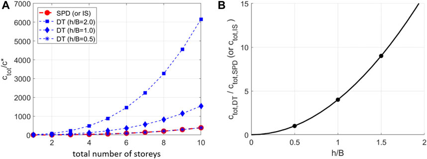
FIGURE 4. (A) ctot for SPD (or IS) and DT systems vs total number of storeys N; (B)
The GSDOF approach here used to determine the damping ratio of the damped frames connected to a strongback can be easily applied to any added dampers configuration, since, thanks to the presence of the strongback, the along-the-height lateral deformed shape remains linear and is not affected by the presence of the added dampers, as instead occurs for the case of frames without strongback. In fact, for particular dampers configurations, as those with diagonal dampers inserted in selected storeys where highly non-classical damping mechanism governs the energy dissipation process, the effectiveness of the damping system cannot be captured by the dynamics of the GSDOF system, as shown in the work of Palermo et al. (2020).
In the next section, specific dampers configurations are investigated through numerical simulations with the main purposes of i) verifying the effectiveness of the formulas derived for the different damped frames connected with a strongback and ii) comparing the seismic performances of the same damping system with and without the strongback.
Numerical Simulations
Analyzed Systems and Input
A 6-storey one-bay uniform frame is considered as a case study. The frame columns are made with European HE320B profiles (
The following BF systems are considered:
• BF-NAKED: bare frame structure;
• BF-SPD: bare frame structure equipped with the SPD system;
• BF-IS1: bare frame structure equipped with an IS system with the damper placed at the first storey;
• BF-IS3: bare frame structure equipped with an IS system with the damper placed at the third storey;
• BF-IS6: bare frame structure equipped with an IS system with the damper placed at the top (sixth) storey.
The following SB systems are considered:
• SB-NAKED: bare frame structure connected to the external rigid strongback;
• SB-SPD: bare frame structure connected to the external rigid strongback and equipped with the SPD system;
• SB-IS1: bare frame structure connected to the external rigid strongback and equipped with an IS system with the damper placed at the first storey;
• SB-IS3: bare frame structure connected to the external rigid strongback and equipped with an IS system with the damper placed at the third storey;
• SB-IS6: bare frame structure connected to the external rigid strongback and equipped with an IS system with the damper placed at the top (sixth) storey;
• SB-DT: bare frame structure connected to the external rigid strongback and equipped with a uniform DT damping system.
For the SB systems, the structural members of the strongback are modelled as rigid elements in order to guarantee a linear along-the-height lateral deformed shape. The FE model of all analyzed systems (displayed in Figure 5) are developed with the computer software (SAP, 2000) v23.1.0.
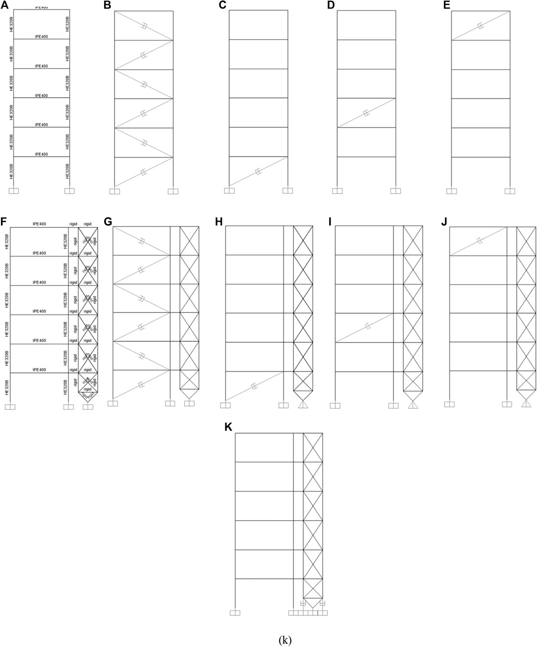
FIGURE 5. (A) BF-NAKED model; (B) BF-SPD model; (C) BF-IS1 model; (D) BF-IS3 model; (E) BF-IS6 model; (F) SB-NAKED model; (G) SB-SPD model; (H) SB-IS1 model; (I) SB-IS3 model; (J) SB-IS6 model; (K) SB-DT model.
The first-mode deformed shape of the uniform BF-NAKED and SB-NAKED models are reported in Figure 6. The BF-NAKED model has a fundamental period equal to 1.28 s and a first-mode deformed shape that is typical of moment-resisting frames with stiff beams (Figure 6A). As expected, the first deformed shape of the SB-NAKED model is instead linear (Figure 6B) and the fundamental period is slightly lower than that of the bare frame (1.20 vs. 1.28 s).
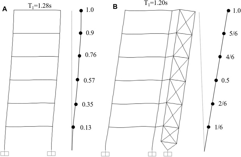
FIGURE 6. (A) First-mode shape of the uniform bare frame; (B) First mode shape of the uniform frame connected with the strongback.
The viscous dampers are sized to obtain a specific target viscous damping ratio (
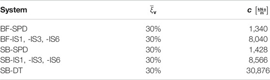
TABLE 2. Damping coefficients for the case study.
Dynamic time-history analyses are performed by: i) reproducing free damped vibrations starting from a given initial deformed configuration with linear along-the-height floor initial displacement and zero initial velocity (snap-back tests) and ii) applying at the base of the analyzed systems the El Centro S00E record (Imperial Valley 1940 earthquake).
Evaluation of the Damping Properties Through Snapback Tests
Numerically simulated snap-back tests are performed with the purpose of estimating the equivalent damping ratio from the response in free vibration. For each system, the damping ratio is calculated according to the logarithmic decrement method (Chopra 2001) considering the time-history response of the top storey. As expected, the damping ratios obtained from the time-history responses of all the damped SB systems and of the BF-SPD system (between 33% and 35%, Figure 7A) are in quite good agreement with the target values (35%). On the contrary, the response in free vibration of the three BF-IS systems (Figure 7B) are quite different from the expected ones and, in some cases, it is not possible to determine the damping ratio according to the logarithmic decrement method (for instance: the response of system BF-IS3). Anyway, even for the cases where the free vibration responses are similar to that of a damped SDOF system (for instance: both the BF-IS1 and the BF-IS6 systems), the values of the damping ratios are far lower than the target ones estimated from the corresponding GSDOF systems. In particular, the response of the BF-IS6 system is quite close to the response of the BF-NAKED system, thus indicating an almost ineffective damping system (similar findings were also obtained in the work by Palermo et al., 2020).
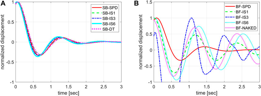
FIGURE 7. (A) Time-history response from snap-back test for the damped SB systems; (B) Time-history response from snap-back test for the BF systems.
Comparing the Seismic Performances of the Systems With and Without Strongback
The seismic performances of selected damped systems are compared considering the peak inter-storey drift ratio (ID) profiles under the El Centro ground motion. The purpose is to evaluate the influence of the presence of the strongback on the effectiveness of the different damping configurations.
Figures 8A,B display the ID profiles for all SB and BF systems. Then, a comparison between the ID profiles for selected models (namely SB-NAKED, BF-NAKED, SB-SPD, BF-SPD, SB-IS6, and BF-IS6) is displayed in Figure 8C. As expected, for the three SB models, the ID profile is uniform along the height, with values in the range of 0.25–0.35 for the damped systems and around 0.7 for the SB-NAKED model. As expected, for the naked model the ID values are not constant along the height and exhibit a very large variability with values ranging from 0.2 (at the peak storey for the BF-SPD model) to almost 1.0 (for both BF-NAKED and BF-IS6 models). The average ID value of the BF-NAKED model is around 0.7, thus close to that of the SB-NAKED. In general, the three BF-IS models exhibit larger ID values with respect to those observed for the BF-SPD model, thus indicating a reduced effectiveness in terms of energy dissipation.
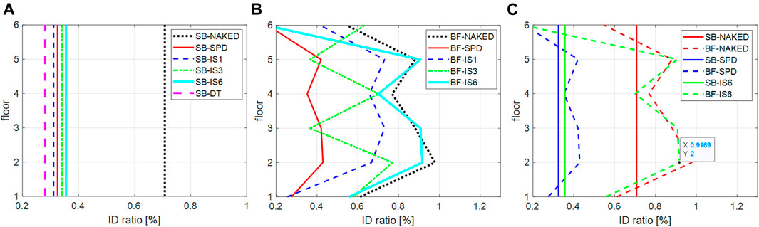
FIGURE 8. (A) ID for the SB systems. (B) ID for the BF systems. (C) Comparison of ID for the SB and BF systems.
For the SB models, also the values of the ID damping reduction factors are computed as the ratio between the peak inter-storey drifts of one damped SB model and the SB-NAKED model. The values are reported in the histogram of Figure 9A. For sake of comparison, the histogram also includes the values of the damping reduction factor obtained i) according to the well-known formulation introduced by Bommer et al., 2000 (leading to a value of
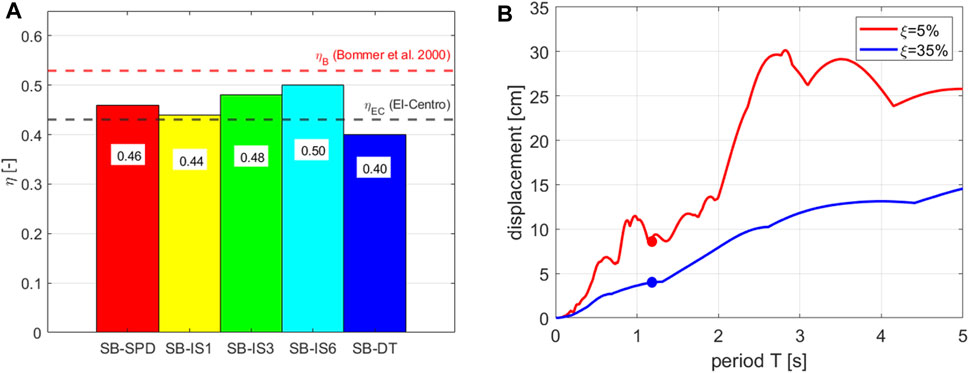
FIGURE 9. (A) Histogram of the damping reduction factors of the ID for the SB systems. (B) Displacement spectra for El-Centro ground motion.
It should be noted that the obtained numerical results are always affected by model uncertainties that lead to unavoidable discrepancies between the theoretical predictions, either analytical or numerical, and the actual response of the structure (especially in the case of non-linear models, Castaldo et al., 2020) which hence should be considered in design applications.
Conclusion
The paper illustrates the main results of a study aimed at investigating the seismic design and performances of frame structures connected with an external strongback system and equipped with different configurations of added viscous dampers. For this study, the strongback system is modelled as an external pinned-base rigid vertical truss system connected with the frame and capable of imposing a linear along-the-height lateral deformed shape, thus limiting potentially dangerous effects associated to soft-storey mechanisms. The supplemental dampers provide extra energy dissipation capabilities to reduce the whole peak displacement response under earthquake excitation. The dynamic behavior of this coupled system is studied in detail for selected configurations of added viscous dampers, including i) dampers inserted within the frame at all storeys leading to a Stiffness Proportional Damping (SPD) system, ii) dampers inserted between two consecutive storeys only (“Inter-Storey” placement, IS system), and iii) dampers inserted at the base of the pinned-base strongback to realize a so-called rigid “Dissipative Tower” (DT system). For the special case of uniform systems (namely systems with uniform inter-storey height and uniform distributions of floor masses, lateral stiffness and viscous dampers), analytical design formulations are derived on the basis of the Generalized Single Degree of Freedom (GSDOF) approach. It provides insights into the dynamic behavior of the coupled system and allows to obtain useful results for the preliminary seismic design of the added viscous dampers in terms of total amount of damping coefficient necessary to achieve a given target damping ratio. The results indicate that the DT system becomes more effective than both SPD and IS systems when the geometrical aspect ratio (inter-storey height over dampers arm) is smaller than 0.5. Finally, the effectiveness of the proposed design equations to size the added dampers are evaluated by means of numerical snap-back and earthquake simulations carried out on uniform SPD, IS and DT systems. It is shown that, especially for the IS systems, the presence of the strongback allows to increase the effectiveness of the damping system, thanks to the uniform dissipation of energy along the whole height of the structure.
Data Availability Statement
The datasets presented in this article will be available upon requests directed to the corresponding author.
Author Contributions
Conceptualization: MP, VL, and SS; Methodology: MP, Visualization: MP and VL; Writing–Original draft: MP, VL, and SS; Writing–Reviewing and Editing: GG; Resources: SS; Supervision: TT.
Conflict of Interest
The authors declare that the research was conducted in the absence of any commercial or financial relationships that could be construed as a potential conflict of interest.
Publisher’s Note
All claims expressed in this article are solely those of the authors and do not necessarily represent those of their affiliated organizations, or those of the publisher, the editors and the reviewers. Any product that may be evaluated in this article, or claim that may be made by its manufacturer, is not guaranteed or endorsed by the publisher.
Acknowledgments
Financial supports of the Italian “Dipartimento della Protezione Civile” (DPC-Reluis 2019–2021 Grant–Research line WP15 “Code contributions for seismic isolation and dissipation”) is gratefully acknowledged.
Appendix 1
A N-storey uniform shear-type frame connected to a rigid strongback is here considered. The system is referred to as SYSTEM A. The floor mass is indicated with m, while the storey lateral stiffness is indicated with k. According to the GSDOF analogy (Palermo et al., 2020), the system can be reduced to two equivalent SDOF systems, by imposing either the global translational equilibrium (Generalized Translational Oscillator - GTO) or the global rotational equilibrium (Generalized Rotational Oscillator - GRO) of the systems of dynamic forces acting on the frame:
Since the strongback is capable of imposing a unique and known linear deformed shape d, the two resulting GSDOF systems are hereafter demonstrated to be characterized by the same circular frequency of vibration.
The attention is focused on the global translational equilibrium equation (Eq. A1) leading to the GTO. For the sake of deriving the circular frequency of vibration of the GTO, it is convenient to introduce SYSTEM B, namely a shear-type frame system with the same uniform floor mass m, connected with the rigid strongback but with a fictitious non-uniform storey lateral stiffness
where:
is the elastic force acting at the i-th storey of the SYSTEM B. The general analytical expression of
Substitution of Eqs. A4, A5 and Eq. 1 into Eq. A1 leads to:
It is easy to recognize that the two terms in brackets are the generalized mass MT and the generalized stiffness KT of the GTO. By definition, the circular frequency of the GTO results equal to:
References
Alavi, B., and Krawinkler, H. (2004). Strengthening of Moment-Resisting Frame Structures against Near-Fault Ground Motion Effects. Earthquake Engng. Struct. Dyn. 33 (6), 707–722. doi:10.1002/eqe.370
Bertero, R. D., and Bertero, V. V. (2002). Performance-based Seismic Engineering: the Need for a Reliable Conceptual Comprehensive Approach. Earthquake Engng. Struct. Dyn. 31 (3), 627–652. doi:10.1002/eqe.146
Bommer, J. J., Elnashai, A. S., and Weir, A. G. (2000). “Compatible Acceleration and Displacement Spectra for Seismic Design Codes,” in Proceeding of the 12th World Conference on Earthquake Engineering, Auckland, New Zealand, January 30th–February 4th 2000.
Castaldo, P., and De Iuliis, M. (2014). Optimal Integrated Seismic Design of Structural and Viscoelastic Bracing-Damper Systems. Earthquake Engng Struct. Dyn. 43 (12), 1809–1827. doi:10.1002/eqe.2425
Castaldo, P., Gino, D., Bertagnoli, G., and Mancini, G. (2020). Resistance Model Uncertainty in Non-linear Finite Element Analyses of Cyclically Loaded Reinforced concrete Systems. Eng. Structures 211, 110496. doi:10.1016/j.engstruct.2020.110496
Chen, C. H., and Mahin, S. A. (2012). “Performance-based Seismic Demand Assessment of Concentrically Braced Steel Frame Buildings.” PEER Rep. 2012/103. Berkeley, CA: Pacific Earthquake Engineering Research Center, University of California.
Chopra, A. K., (2001). Dynamics of Structures: Theory and Applications to Earthquake Engineering. 2nd Edition. Upper Saddle River, New Jersey: Prentice-Hall.
Christopoulos, C., and Filiatrault, A. (2006). Principles of Passive Supplemental Damping and Seismic Isolation. Pavia, Italy: IUSS Press.
Clough, R. W., and Huckelbridge, A. A. (1977). Preliminary Experimental Study of Seismic Uplift of a Steel Frame. Berkeley, CA: Earthquake Engineering Research Center, University of California.
Constantinou, M. C., Soong, T. T., and Dargush, G. F. (1998). Passive Energy Dissipation Systems for Structural Design and Retrofit (Monograph No.1). Buffalo, New York: Multidisciplinary Center for Earthquake Engineering Research.
Deierlein, G., Krawinkler, H., Ma, X., Eatherton, M., Hajjar, J., Takeuchi, T., et al. (2011). Earthquake Resilient Steel Braced Frames with Controlled Rocking and Energy Dissipating Fuses. Steel Construction 4 (3), 171–175. doi:10.1002/stco.201110023
Foutch, D. A., Goel, S. C., and Roeder, C. W. (1987). Seismic Testing of Full‐Scale Steel Building-Part I. J. Struct. Eng. 113 (11), 2111–2129. doi:10.1061/(asce)0733-9445(1987)113:11(2111)
Gioiella, L., Tubaldi, E., Gara, F., Dezi, L., and Dall'Asta, A. (2018). Modal Properties and Seismic Behaviour of Buildings Equipped with External Dissipative Pinned Rocking Braced Frames. Eng. Structures 172, 807–819. doi:10.1016/j.engstruct.2018.06.043
Hines, E. M., and Appel, M. E. (2007). “Behavior and Design of Low Ductility Braced Frames,” in Proceeding of the Structures Congress: New Horizons and Better Practices, ASCE Structures Congress 2007, Long Beach, CA, United States, May 16–19, 2007, 1–8. doi:10.1061/40946(248)51
Hines, E. M., Appel, M. E., and Cheever, P. J. (2009). Collapse Performance of Low-Ductility Chevron Braced Steel Frames in Moderate Seismic Regions. AISC Eng. J. 46 (3), 149–180.
Kelly, J. M., and Tsztoo, D. F. (1977). Earthquake Simulation Testing of a Stepping Frame with Energy-Absorbing Devices, Rep. UCB/EERC-77/17. Berkeley, CA: Earthquake Engineering Research Center, University. of California. doi:10.5459/bnzsee.10.4.196-207
Khatib, I. F., Mahin, S. A., and Pister, K. S. (1988). Seismic Behavior of Concentrically Braced Steel Frames, Berkeley, CA: Earthquake Engineering Research Center, University. of California.
Kiggins, S., and Uang, C.-M. (2006). Reducing Residual Drift of Buckling-Restrained Braced Frames as a Dual System. Eng. Structures 28 (11), 1525–1532. doi:10.1016/j.engstruct.2005.10.023
Lai, J.-W., Chen, C.-H., and Mahin, S. A. (2010). Experimental and Analytical Performance of Concentrically Braced Steel Frames. Structures Congress 2010, 2339–2350. doi:10.1061/41130(369)212
Lai, J.-W., and Mahin, S. A. (2014). Strongback System: a Way to Reduce Damage Concentration in Steel-Braced Frames. J. Struct. Eng. 141 (9), 04014223, doi:10.1061/(asce)st.1943-541x.0001198
Nuzzo, I., Losanno, D., Caterino, N., Serino, G., and Bozzo Rotondo, L. M. (2018). Experimental and Analytical Characterization of Steel Shear Links for Seismic Energy Dissipation. Eng. Structures 172, 405–418. doi:10.1016/j.engstruct.2018.06.005
Palermo, M., Laghi, V., Gasparini, G., Silvestri, S., and Trombetti, T. (2020). Estimating Fundamental Dynamic Properties of Structures with Supplemental Dampers by Means of Generalized Single Degree of Freedom Systems. J. Earthquake Eng., 1–30. doi:10.1080/13632469.2020.1816231
Palermo, M., Laghi, V., Gasparini, G., and Trombetti, T. (2018b). Coupled Response of Frame Structures Connected to a Strongback. J. Struct. Eng. 144 (9), 04018148. doi:10.1061/(asce)st.1943-541x.0002134
Palermo, M., Ricci, I., Gagliardi, S., Silvestri, S., Trombetti, T., and Gasparini, G. (2014). Multi-performance Seismic Design through an Enhanced First-Storey Isolation System. Eng. Structures. 59, 495–506. doi:10.1016/j.engstruct.2013.11.002
Palermo, M., Silvestri, S., Gasparini, G., and Trombetti, T. (2015). Crescent Shaped Braces for the Seismic Design of Building Structures. Mater. Struct. 48 (5), 1485–1502. doi:10.1617/s11527-014-0249-z
Palermo, M., Silvestri, S., Landi, L., Gasparini, G., and Trombetti, T. (2018a). A "direct Five-step Procedure" for the Preliminary Seismic Design of Buildings with Added Viscous Dampers. Eng. Struct. 173, 933–950. doi:10.1016/j.engstruct.2018.06.103
Pan, P., Wu, S., Wang, H., and Nie, X. (2018). Seismic Performance Evaluation of an Infilled Rocking wall Frame Structure through Quasi-Static Cyclic Testing. Earthq. Eng. Eng. Vib. 17 (2), 371–383. doi:10.1007/s11803-018-0447-8
Qu, Z., Wada, A., Motoyui, S., Sakata, H., and Kishiki, S. (2012). Pin-supported walls for Enhancing the Seismic Performance of Building Structures. Earthquake Engng Struct. Dyn. 41 (14), 2075–2091. doi:10.1002/eqe.2175
Qu, Z., Ye, L., and Wada, A. (2011). “Seismic Damage Mechanism Control of RC Ductile Frames from a Stiffness point of View,” in Proceeding of the 8th International Conf. on Urban Eart. Eng., Tokyo, Japan.
Rai, D. C., and Goel, S. C. (1997). Seismic Evaluation and Upgrading of Existing Steel Concentric Braced Structures, Rep. UMCEE 97-03. Ann Arbor, MI: Dept. of Civil and Environmental Engineering, Univ. of Michigan.
Roia, D., Gara, F., Balducci, A., and Dezi, L. (2013). “Dynamic Tests On An Existing Rc School Building Retrofitted With “Dissipative Towers”,” in Proceeding Of 11th International Conference On Vibration Problems, Lisbon, Portugal, 9–12 September 2013.
Sabelli, R. (2001). Research on Improving the Design and Analysis of Earthquake-Resistant Steel-Braced Frames. in 2000 NEHRP Professional Fellowship Rep., PF2000-9. Oakland, CA: Earthquake Engineering Research Institute.
SAP (2000). SAP 2000 Version 23 [Computer Software]. Walnut Creek, CA: Computer and Structures, Inc.
Silvestri, S., Gasparini, G., and Trombetti, T. (2010). A Five-step Procedure for the Dimensioning of Viscous Dampers to Be Inserted in Building Structures. J. Earthquake Eng. 14 (3), 417–447. doi:10.1080/13632460903093891
Simpson, B. G., and Mahin, S. A. (2018). Experimental and Numerical Investigation of Strongback Braced Frame System to Mitigate Weak story Behavior. J. Struct. Eng. 144 (2), 04017211. doi:10.1061/(asce)st.1943-541x.0001960
Stavridis, A., and Shing, P. B. (2010). Hybrid Testing and Modeling of a Suspended Zipper Steel Frame. Earthquake Eng. Struct. Dyn. 39 (2), 187–209. doi:10.1002/eqe.940
Sun, T., Kurama, Y. C., Zhang, P., and Ou, J. (2018). Linear-elastic Lateral Load Analysis and Seismic Design of Pin-Supported wall-frame Structures with Yielding Dampers. Earthquake Engng Struct. Dyn. 47 (4), 988–1013. doi:10.1002/eqe.3002
Tirca, L., and Tremblay, R. (2004). “Influence of Building Height and Ground Motion Type on the Seismic Behavior of Zipper Concentrically Braced Steel Frames,” in Proceeding of the 13th World Conference on Earthquake Engineering, Vancouver, Canada, August 1–6 2004.
Toorani, A., Gholhaki, M., and Vahdani, R. (2020). The Investigation into the Effect of Consecutive Earthquakes on the Strongback Bracing System. Structures 24, 477–488. doi:10.1016/j.istruc.2020.01.018
Tremblay, R. (2003). Achieving a Stable Inelastic Seismic Response for Multi-story Concentrically Braced Steel Frames. AISC Eng. J. 40 (2), 111–129.
Trombetti, T., and Silvestri, S. (2004). Added Viscous Dampers in Shear-type Structures: the Effectiveness of Mass Proportional Damping. J. Earthquake Eng. 8 (2), 275–313. doi:10.1080/13632460409350490
Uriz, P., and Mahin, S. A. (2008). Toward Earthquake-Resistant Design of Concentrically Braced Steel-Frame Structures, PEER Rep. 2008/08, Pacific. Berkeley, CA: Earthquake Engineering Research Center, University. of California.
Wang, X., Wang, T., and Qu, Z. (2018). An Experimental Study of a Damage-Controllable Plastic-Hinge-Supported wall Structure. Earthquake Engng Struct. Dyn. 47 (3), 594–612. doi:10.1002/eqe.2981
Whittaker, A. S., Uang, C.-M., and Bertero, V. V. (1990). An Experimental Study of the Behavior of Dual Steel Systems, Rep. UCB-EERC-88/14. Berkeley, CA: Earthquake Engineering Research Center, University. of California.
Wu, S., Pan, P., Nie, X., Wang, H., and Shen, S. (2017). Experimental Investigation on Reparability of an Infilled Rocking wall Frame Structure. Earthquake Engng Struct. Dyn. 46 (15), 2777–2792. doi:10.1002/eqe.2930
Wu, S., Pan, P., and Zhang, D. (2016). Higher Mode Effects in Frame Pin-Supported wall Structure by Using a Distributed Parameter Model. Earthquake Eng. Struct. Dyn. 45, 2371–2387. doi:10.1002/eqe.2706
Yang, C.-S., Leon, R. T., and DesRoches, R. (2010). Cyclic Behavior of Zipper-Braced Frames. Earthquake Spectra. 26 (2), 561–582. doi:10.1193/1.3389483
Yang, C. S., Leon, R. T., and Des Roches, R. (2008). Pushover Response of a Braced Frame with Suspended Zipper Struts. J. Struct. Eng. 10 (1619), 1619–1626. doi:10.1061/10.1061/(asce)0733-9445(2008)134:10(1619)
Keywords: strongback, frame structure, generalized single degree of freedom, supplemental viscous dampers, equivalent damping ratio
Citation: Palermo M, Laghi V, Gasparini G, Silvestri S and Trombetti T (2021) Seismic Design and Performances of Frame Structures Connected to a Strongback System and Equipped with Different Configurations of Supplemental Viscous Dampers. Front. Built Environ. 7:748087. doi: 10.3389/fbuil.2021.748087
Received: 27 July 2021; Accepted: 13 September 2021;
Published: 12 October 2021.
Edited by:
Farhad Behnamfar, Isfahan University of Technology, IranReviewed by:
Paolo Castaldo, Politecnico di Torino, ItalyGiacomo Navarra, Kore University of Enna, Italy
Copyright © 2021 Palermo, Laghi, Gasparini, Silvestri and Trombetti. This is an open-access article distributed under the terms of the Creative Commons Attribution License (CC BY). The use, distribution or reproduction in other forums is permitted, provided the original author(s) and the copyright owner(s) are credited and that the original publication in this journal is cited, in accordance with accepted academic practice. No use, distribution or reproduction is permitted which does not comply with these terms.
*Correspondence: Vittoria Laghi, dml0dG9yaWEubGFnaGkyQHVuaWJvLml0