 Iván M. Díaz
 Christian A. Gallegos
 José Ramírez Senent
 Carlos M. C. Renedo
- Department of Continuum Mechanics and Theory of Structures, E.T.S. de Ingenieros de Caminos, Canales y Puertos, Universidad Politécnica de Madrid, Madrid, Spain
Inertial mass controllers, including passive, semi-active and active strategies, have been extensively used for canceling human-induced vibrations in lightweight pedestrian structures. Codes to check the vibration serviceability and current controller design approaches assume that both excitation forces and controller forces are the same on a flexible structure and on a rigid structure. However, this fact may not be assumable since interaction phenomena arise even for moderately lightweight structures. Analyzing two case studies in this paper, interaction phenomena involved in the frequency-domain-based design of passive and active inertial mass dampers are discussed. Thus, a general vibration control problem including the interaction phenomena is set hereby. Concretely, this paper deeply discusses the following issues: (i) how the structure to be controlled is affected when human-structure interaction is presented for deterministic and stochastic conditions, (ii) the closed-loop transfer function of the controlled structure including a passive inertial mass damper, and (iii) the closed-loop transfer function of the controlled structure including an active inertial mass damper. In addition, the performed analysis considers the actuator dynamics and the actuator-structure interaction.
Introduction
Inertial vibration controllers have been extensively used for canceling human-induced vibrations. Examples can be found in footbridges, long-span floors, grandstands, etc. Most of the applications are based on the so-called Tuned Vibration Absorber (TVA) (also known as Tuned Mass Damper) (Elias and Matsagar, 2017), which is an inertial vibration controller working passively. The TVA is tuned to a specific vibration mode, so detuning problems arise when the structure model properties change over time or the device modifies its properties. Hence, approaches such as multi-TVA (Caetano et al., 2010; Van Nimmen et al., 2016) and semi-active TVA (Soria et al., 2017; Moutinho et al., 2018) have been applied to alleviate these issues.
The detuning issue becomes even more detrimental when dealing with the vibration control of very lightweight pedestrian structures. Different from traditional footbridges in which resonant responses up to 5 Hz are considered for the vibration serviceability analysis, very lightweight structures may show non-negligible non-resonant responses up to even 10 Hz (Russell et al., 2019). Additionally, the mass of the occupants may not be negligible as compared to the structural modal mass and, consequently, active occupants cannot be modeled as a simple dead load since interaction phenomena arisen between occupants and the structure. Therefore, responses out of the structure resonances and the Human-Structure Interaction (HSI) should be accounted for the design of TVAs.
The active version of the TVA, known as Active Vibration Absorber (AVA), has also been successfully implemented in laboratory and in-service structures to cope with excessive human-induced vibrations. An AVA system basically comprises: (i) the actuator(s), which transmits controlled forces to the target structure so as to minimize its vibrations, (ii) the control system, which calculates in real-time the command (voltage) signal to the actuator, so that the target forces are developed and (iii), the sensors located on the structure, which provide the kinematic information (usually acceleration) required for the controller to calculate the command signal. Several morphologies of actuators have been employed for active vibration control, some examples are electromagnetic proof-mass actuators (Casado et al., 2013; Zhang and Ou, 2015; Mao and Huang, 2019), pneumatic muscle actuators (Bleicher et al., 2011), and multiple rotating-mass actuators (Terrill et al., 2020), amongst others.
The most challenging part to design in an AVA system is the control algorithm. The most widespread technique is the Direct Velocity Feedback Control in which the velocity of the structure is estimated by integrating the accelerometer signal. If an ideal actuator and sensor are considered, the closed-loop system is unconditionally stable (independent from the control gain). Nevertheless, this assumption is only valid if the resonant frequency of the actuator is much lower than the target frequencies of the structure. When a real actuator is considered, its dynamics interfere with the overall system dynamics, yielding to a conditionally stable system. In this case, the root locus of the closed-loop system shows a couple of branches which enter the right-half plane from a certain value of the control gain on. Several approaches have been proposed to increase the stability margin of AVA systems, such as: Modified Acceleration Feedback (Díaz and Reynolds, 2009), the Internal Resonant Control (Díaz et al., 2012b), the Inner Control Loop approach (Díaz et al., 2012a), or the Virtual Mass technique (Mao et al., 2020).
Actuator dynamics are usually considered to be independent of the structural response. However, this hypothesis only holds when structural displacements are negligible in comparison to those of the actuator inertial mass. Hence, the force transmitted by the actuator depends only on the command signal and its own inherent dynamics. This scenario is modeled by using the well-known second-order proof-mass actuator model (Preumont, 2002), or a three-order model (Díaz and Reynolds, 2009) when the electrical subsystem plays a significant role on the actuator transfer function (TF). Nevertheless, when dealing with lightweight flexible structures, the motion of the structure may affect significantly the motion of the actuator inertial mass and the Actuator-Structure Interaction (ASI) phenomenon can no longer be neglected.
Regarding human-induced loads, experimental campaigns using force plates (Parkhouse and Ewins, 2006), sensors (Moreu et al., 2020), shoe insoles (Wang H. et al., 2019), or computer vision approaches (Wang Y. et al., 2019), to mention a few, have been carried out to accurately characterize these actions. Thus, deterministic (Boniface et al., 2006; Heinemeyer et al., 2009) or stochastic (Casciati et al., 2017; Ramos-Moreno et al., 2020) models have been proposed over the years to predict the dynamic response of structures under the human actions. Codes and control design approaches consider that forces generated by human activities are the same on a flexible structure and on a rigid structure. However, this assumption might not hold even for moderately lightweight structures, such as grandstands or footbridges, since the response may be poorly estimated (Ahmadi et al., 2019). In these cases, humans will react to the behavior of flexible structure when they perceive the vibration by modifying their gait, and the so-called HSI phenomenon arises.
Although pedestrian actions have been modeled by point periodic forces (ISO, 2012; CEN, 2020), it is well accepted that the dynamic properties of the human body affect the vibration serviceability of the structure (Van Nimmen et al., 2017). Since the structure response may be reduced when human dynamics are considered, single-degree-of-freedom (SDOF) (biodynamic) models have been proposed in the literature for different types of human actions (Jones et al., 2011; Shahabpoor et al., 2016; Silva et al., 2020). In general, it is accepted that the interaction only takes place when displacements are large, at much higher levels than those prescribed in codes. On the other hand, when the inertial control starts to cancel out the vibration, this level is usually high and the system to be controlled may be significantly modified by the human influence (coupled human-structure system). Consequently, when designing vibration control strategies to meet the vibration serviceability, HSI plays an important role and should not be generally ignored.
This paper sets the general vibration control problem for the design of inertial controllers when dealing with very lightweight flexible pedestrian structures. The paper gathers the interaction phenomena that should be accounted for vibration control of these structures. Thus, the open-loop TF for the structure with HSI is firstly derived, and secondly, the closed-loop TF for TVA and AVA (without and with ASI) are obtained. Hence, it is shown how the interactions affect both the open and the closed-loop TFs, and consequently, the controller design in the frequency domain.
Regarding the AVA, collocated and non-model-based control is assumed hereby, that is, the vibration is measured and canceled out at the same physical point and no model is used within the control law implementation, respectively. Control strategies based on collocated actuators and sensors have been demonstrated to offer greater robustness, stability, performance and ease of implementation with respect to full state-space feedback control system and model-based approaches. Thus, a human-structure dynamic collocated model based on the fairly simple and geared-to-practice mass-spring-damper-actuator model is adopted based on Dougill et al. (2006).
After this introduction, the general equations of motion and the TFs of the general control scheme are described in Section “System Modelling.” In Section “Case Study: FRP Footbridge,” a case study is presented considering a very lightweight fiber reinforced polymer (FRP) laboratory footbridge. This plant (without and with HSI) is analyzed under deterministic and stochastic assumptions, and the results of the closed-loop model are compared with the outcomes of a FE model. In Section “Controllers Design,” the design of TVA and AVA systems is presented for the studied plant. For the AVA systems, the stability and dynamic properties in the following scenarios are studied, giving directions for controller design: (i) ideal actuator case, (ii) real actuator case, (iii) real actuator case with ASI, (iv) real actuator case with ASI and HSI. Section “Discussion” presents a discussion of the implications of HSI considering another lightweight FRP footbridge with lower fundamental natural frequency and employing the proposed methodology. In the remainder of the paper, Section “Conclusion and Future Perspective,” conclusions and some future works are drawn.
System Modeling
The models of the plant to be controlled, human, and inertial controllers involved in the control scheme are described in this section.
Plant Model
A SDOF model for the plant is depicted in Figure 1A, and its equation of motion is
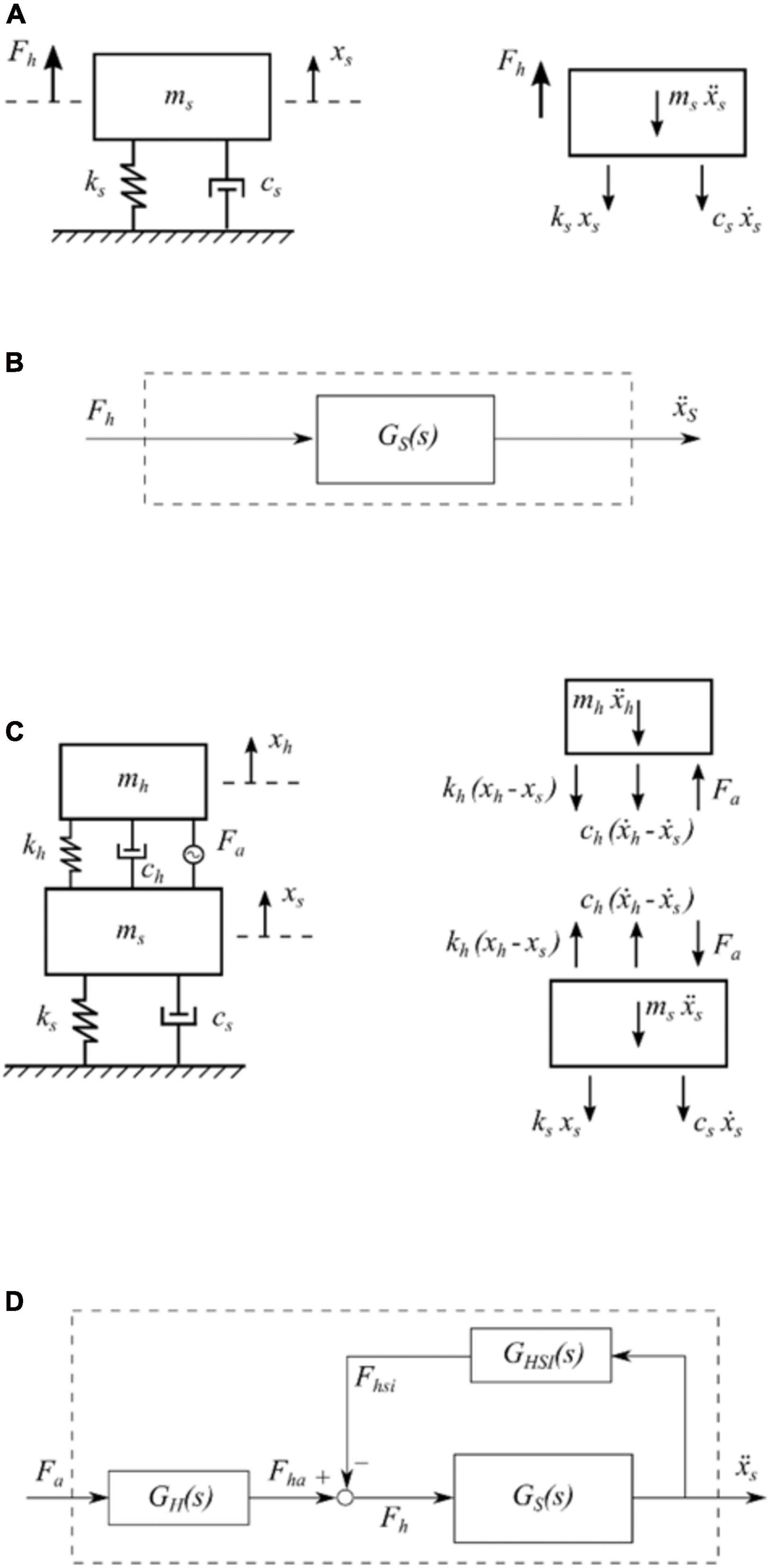
Figure 1. Models of the systems: (A) Plant free body diagram, (B) Plant block diagram, (C) HSI free body diagram, and (D) HSI block diagram.
where xs = xs(t) (m) is the displacement of the structure at the control point (over dots indicating time derivatives.), (N/m) is the structure’s stiffness, ωs = 2πfs (rad/s) is the circular natural frequency of the structure, cs = 2ωsmsζs (Ns/m) is the viscous damping of the structure, and Fh (N) is the excitation force acting on the structure.
Taking the Laplace transform of Eq. 1 and considering the contribution of several vibration modes, the TF between the acceleration response and the force at the control point is
with i = 1, 2,…Ns, where Ns is the number of considered modes of the structure, s is the Laplace variable, Fh(s) is the Laplace transform of the external human force acting on the structure, and s2Xs(s) is the Laplace transform of the structural acceleration, being Xs(s) the Laplace transform of the structural displacement. Figure 1B shows the block diagram of the plant.
Human Interactive Model
A mass-spring-damper-actuator system based on the dynamic properties of the human body and attached to the structure is employed to account for HSI phenomenon. Thus, a human is defined by means of its mass (mh), natural frequency (fh), and damping ratio (ζh). Additionally, a harmonic force generated by the human legs is considered as a pair of action-reaction forces acting simultaneously on both the structure and the human, here named as human driving force and denoted by Fa(N).
When considering HSI, the dynamic analysis of the coupled human-structure system is carried out assuming that the interaction can be modeled as a closed-loop system, in which the human actions are fed back to the structure. Considering one person acting on the structure, this feedback loop is easily deducted from the force balance illustrated in Figure 1C for a SDOF model for the structure, which is governed by the following expressions
where xh (m) is the human displacement, (N/m) is the stiffness of the human model, ωh = 2πfh (rad/s) is the human’s circular natural frequency, ch = 2ωhmhζh (Ns/m) is the viscous damping of the human, and Fhsi (N) is the transmitted passive force between the structure and the human.
From the Laplace transform of Eqs. 3–5, the block diagram of the coupled human-structure system is derived as shown in Figure 1D. This diagram uses the structure TF (see Eq. 2) and two additional TFs that account for: (i) the force generated by humans without structure movement GH(s), and (ii) the human interactive force GHSI(s). Thus, for an Nh number of humans acting at the control point, these two TFs are defined as follows
with j = 1, 2,…Nh, where Fha is the force generated by the humans without including the force transmitted to them due to the structure movement. Then, the TF of the coupled human-structure system is as follows
Tuned Vibration Absorber
The TVA-structure coupled model is firstly designed assuming a SDOF model for the structure. The control force entering the structural system is obtained from the transmitted force (Ft) of the TVA. Figure 2A shows the system of the structure that includes a TVA, which is governed by these equations of motion
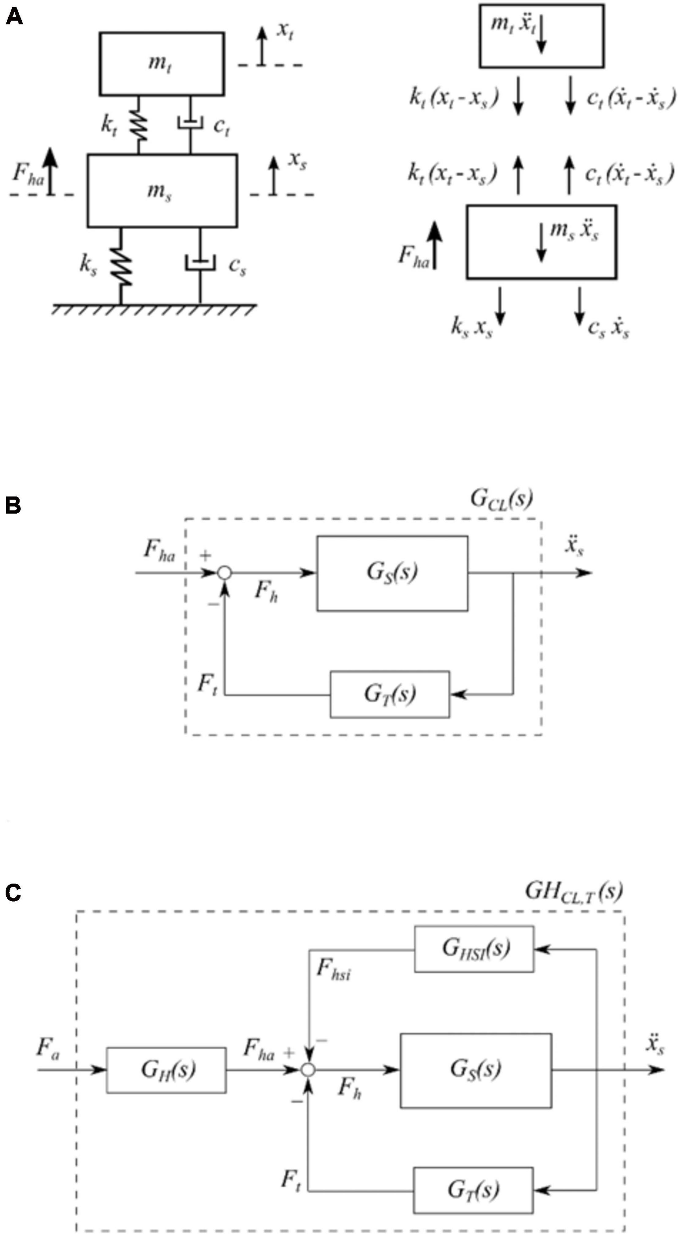
Figure 2. TVA system: (A) Free body diagram, (B) Block diagram of the plant with a TVA, and (C) Block diagram of the plant with a TVA and HSI.
where xt (m) is the TVA displacement, (N/m) is the stiffness of the passive inertial controller, ωt = 2πft (rad/s) is its circular natural frequency, ft (Hz) is the respective natural frequency, mt (kg) is the mass of the device, ct = 2ωtmtζt (Ns/m) is the viscous damping of the device, and ζt is the TVA damping ratio.
From Eqs. 9–11, the TF between Ft and the structure acceleration is the following
For the system omitting the interaction phenomenon, the passive controller attached to the plant is defined by the closed-loop scheme (GCL,T) presented below
where GS is shown in Eq. 2, and GT is presented in Eq. 12. The block diagram of the system represented by Eq. 13 is depicted in Figure 2B. On the other hand, the closed-loop scheme (GHCL,T) that represents the TVA system with the plant considering HSI is
in which the TFs employed are defined in Eqs. 2, 6, 7, and 12. The block diagram this system is shown in Figure 2C.
Active Vibration Absorber
The TFs for the AVA system are derived next. The equations of motion assuming a SDOF model for the structure (see Figure 3A) are
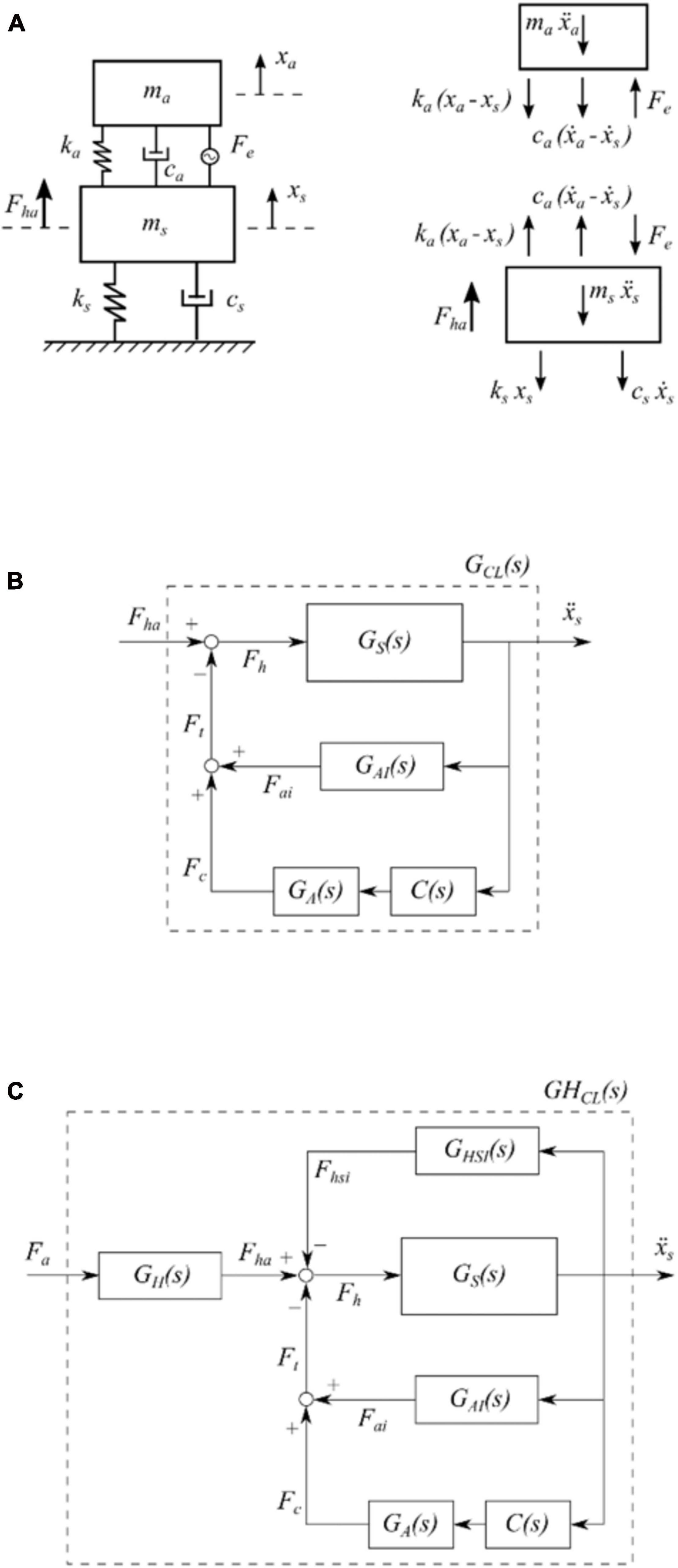
Figure 3. AVA system: (A) Free body diagram, (B) Block diagram of the plant with an AVA, and (C) Block diagram of the plant with an AVA and HSI.
for the structure, and
for the proof-mass actuator, in which xa (m) is the displacements of the actuator inertial mass, and Fe (N) is the (electromagnetic) force developed by the actuator. Furthermore, ma (kg) is the sprung/moving mass of the actuator and ka (N/m) and ca (Ns/m) are, respectively, its stiffness and viscous damping.
The force transmitted to the structure due to the actuator can be expressed as
Taking the Laplace transform of Eq. 16, multiplying both sides by mas2 and accounting for Eq. 17 yields
which represents the Multiple Input Single Output TF between the force transmitted to the structure by the actuator and the electromagnetic force F_e and the structure acceleration . The latter represents the ASI.
Making use of the relationship Fe(t) = Ke⋅V(t), which relates the electromagnetic force developed by the actuator and its control voltage, the TF between the force transmitted by the proof-mass actuator and its input voltage, in case of a perfectly rigid structure, can be expressed as follows
in which Ke > 0 (N/V) is the force constant of the proof-mass actuator, ωa = 2πfa (rad/s) is its circular natural frequency, f_a (Hz) is the correspondent natural frequency and ζa is the damping ratio of the device. It is worth noting that a second order TF has been obtained, since the electro-mechanical velocity coupling has been neglected. This is equivalent to considering a perfect transconductance amplifier (Preumont, 2002).
The TF accounting for the force transferred to the structure due to its interaction with the proof-mass actuator (second term of the right-hand side of Eq. 18) can be cast as
The selected control strategy is DVFC, thus, the voltage input to the actuator is determined by means of a controller whose output is proportional to the estimated velocity of the structure. The TF of this controller has been idealized, for the sake of clarity, as a pure integrator affected by a control gain Kv as follows
More realistic approaches make use of a band-pass filter to estimate the velocity from the acceleration of the structure (Díaz and Reynolds, 2009). The block diagrams of the resulting structural systems, neglecting and accounting for HSI, with the previously explained TFs are shown in Figures 3B,C, respectively. The closed-loop TF of the overall system without HSI, GCL, is expressed as follows
and finally, the closed-loop TF with HSI, GHCL,is
Case Study: FRP Footbridge
A lightweight FRP footbridge is studied in this section together with uncertainties in its dynamic properties (equivalent modal mass, natural frequency and damping ratio). Also, the design of the controllers is presented.
Structure Description
The pedestrian bridge is a 10-m long simply supported FRP structure with a width of 1.5 m. Figure 4A shows the plan view of the footbridge that comprises pultruded Glass FRP (GFRP) profiles and Carbon FRP (CFRP) strips manufactured by Fiberline Composites A/S. (2018). The main elements are three GFRP profiles, one I 300 × 150 × 15 and two U 300 × 90 × 15, separated 0.75 m transversally. Also, CFRP strips (E 139/90/4.9 and E 139/150/4.9) are bonded to the top and bottom flanges of the stringers along their entire length, as depicted in Figure 4B. GFRP I 160 × 80 × 8 elements spaced 1.25 m from the pinned supports and every 1.20 m along the rest of the bridge length are the crossbeams acting as lateral restraints.
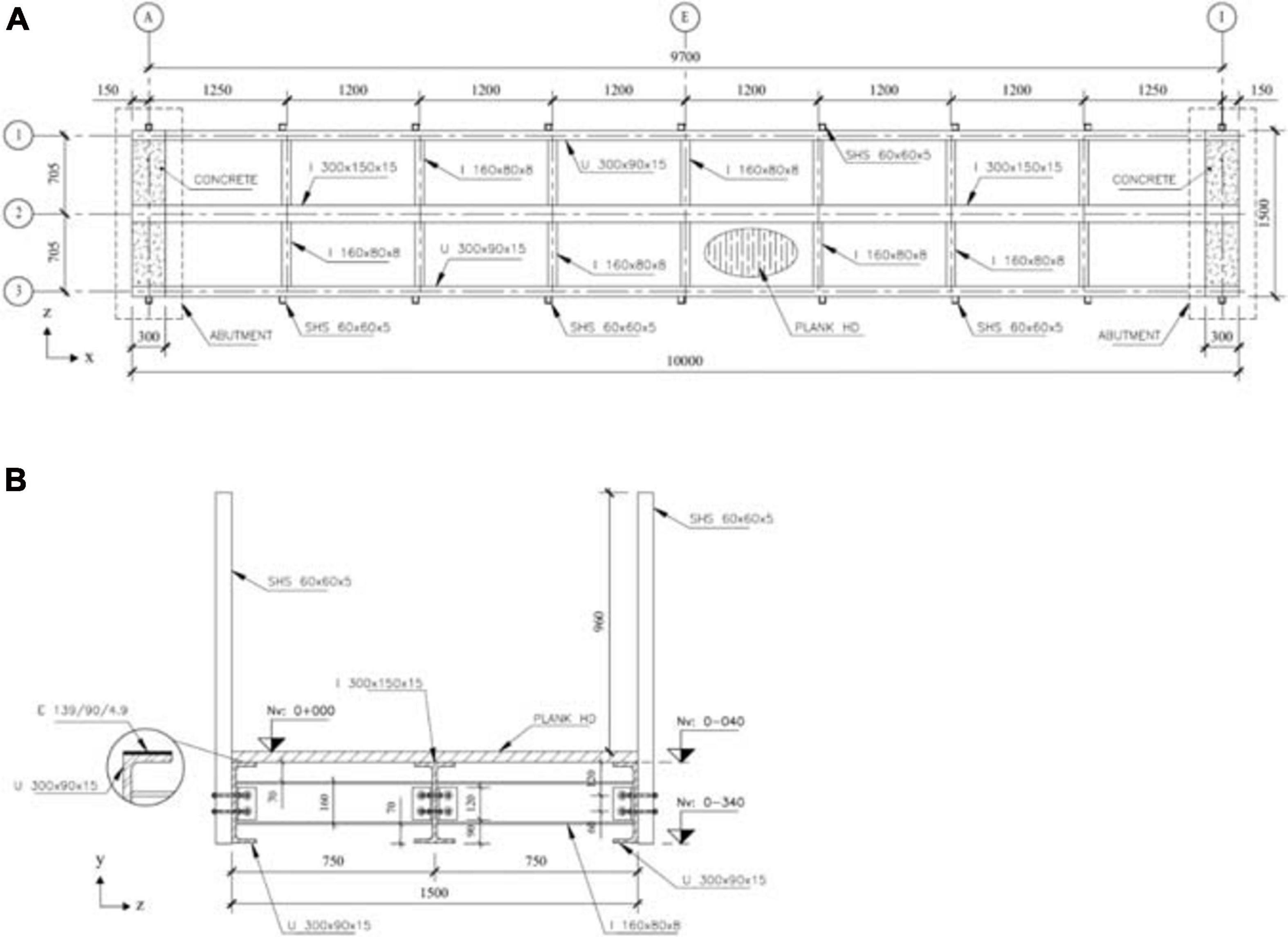
Figure 4. FRP footbridge: (A) Plan view, and (B) Cross-section.
GFRP plank HD panels form the bridge deck, and a layer of recycled rubber pavement is considered as a wearing surface. Stainless steel cables crossing GFRP SHS 60 × 60 × 5 profiles form the handrails, and the square hollow sections are connected to the side of each U profile every intersection between the stringer and the crossbeam. At the support region, concrete with a compressive strength of 30 MPa is cast (see Figure 4A) to ease the construction of the pinned and roller supports. Thus, the concrete blocks at the bridge ends are 1.5 m by 0.3 m by 0.3 m. To assemble the structure, GFRP L 75 × 75 × 8 profiles and stainless-steel bolts are employed.
Finite Element Model
Considering the aforementioned information, a linear elastic FE model of the structure is developed in Abaqus (SIMULIA, 2017). Figure 5A shows the model that uses shell elements (S4R) to represent the stringers, crossbeams, handrail poles, and the deck panels. Whilst solid elements (C3D8R) are used to model the concrete blocks at both ends of the footbridge. Top and bottom flanges of the stringers are defined as shell composite layups comprized of two plies. The first layer refers to the GFRP laminate, and the second one corresponds to the CFRP strip.
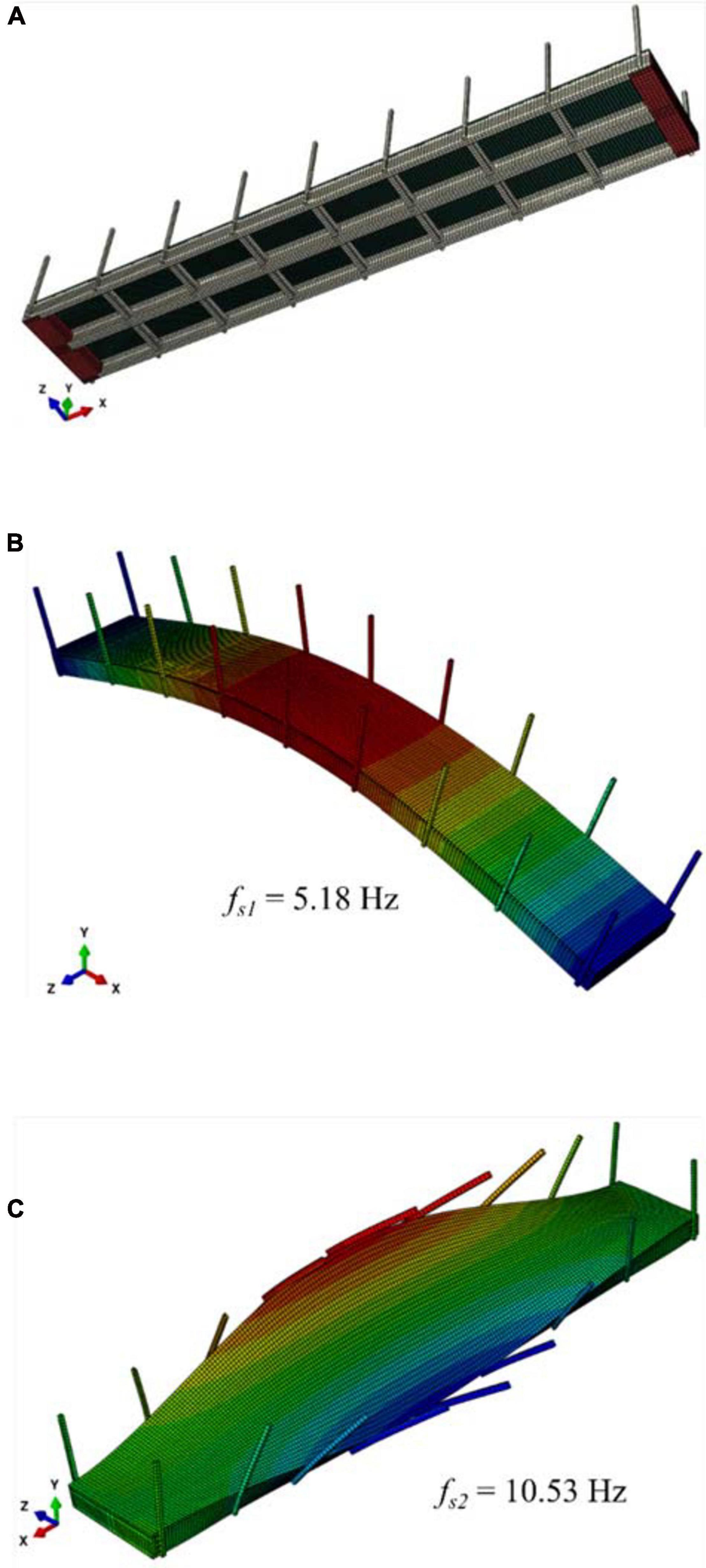
Figure 5. Pedestrian bridge: (A) FE model, (B) First vibration mode, and (C) Second vibration mode.
Tie constraints are selected to join the stringers, crossbeams, and handrail poles, and connections between the stringers and the deck are defined similarly. The stringers are connected to the concrete blocks by using the embedded element technique, so the solid elements are hosts for the shell elements. Properties of the FRP elements are presented in Table 1, and the concrete mechanical properties are assumed as follows: density ρc = 2,400 kg/m3, Young’s modulus Ec = 28 GPa, and Poisson’s ratio νc = 0.30.
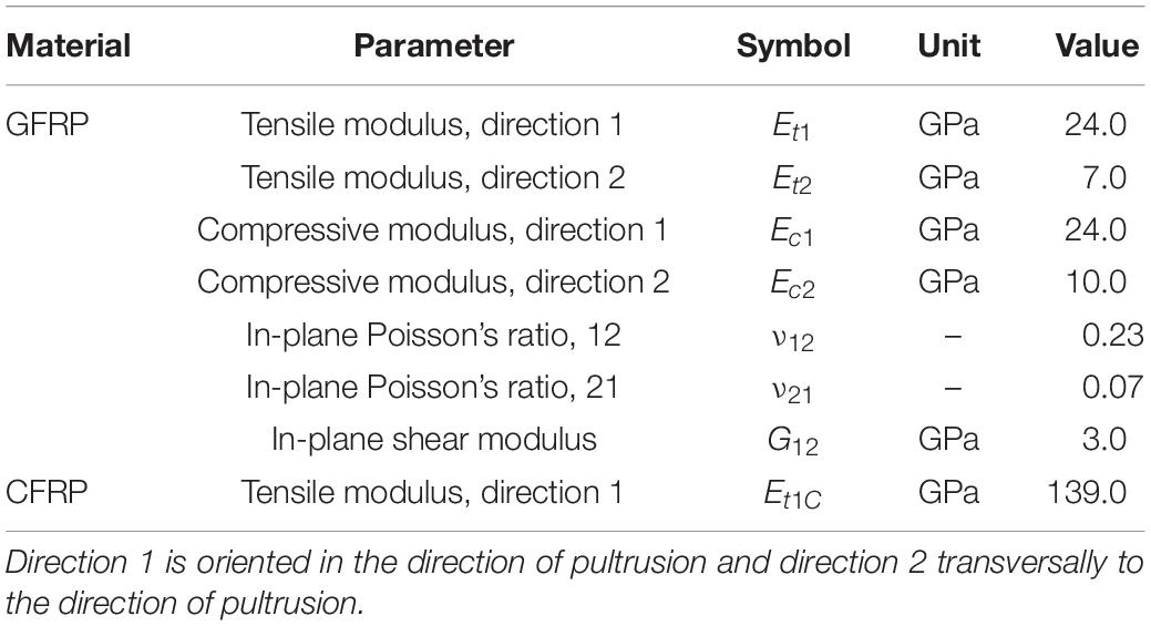
Table 1. Characteristic stiffness values of the FRP elements.
To represent a simply supported structure, displacements of two areas of 0.20 m by 0.15 m at the bottom of one concrete block are constrained in the longitudinal, transversal and vertical (x, y and z) direction. Whilst, only vertical (y) and transversal (z) displacements of two similar areas at the bottom of the other block are constrained. An additional mass of 60 kg/m2 is also defined over the bridge deck to account for all the non-structural components omitted in the model.
Equivalent Structure Model
Based on Section “Plant Model,” the plant model is constructed. In general, all the vibration modes with natural frequencies below 10 Hz, which are likely to be excited by human actions, should be considered. Thus, only the first vertical mode is selected (see Figures 5B,C) for the analysis. A SDOF model is derived after performing a modal analysis using the FE model. An equivalent modal mass (ms) of 837.9 kg and a natural frequency (fs) of 5.18 Hz are obtained. To complete the required data for the model, a damping ratio (ζs) of 2% is assumed (Ascione et al., 2016; Wei et al., 2019).
To characterize the influence of environmental and physical conditions on the FRP structure, statistical distributions are employed to describe its dynamic parameters. First, statistical properties related to the effective modal mass are obtained by carrying out 1000 modal analysis using the FE model (see Figure 5A). As composite elements were manufactured through pultrusion, density of the GFRP and the CFRP are assumed to be constants. Just the non-structural mass varies following a Normal distribution with a mean value of 60 kg/m2 and a coefficient of variation (COV) of 4% (JCSS, 2001). The obtained value for the equivalent modal mass is 837.9 kg and the COV is 2%.
Second, the natural frequency and damping ratio of the footbridge are assumed to be described by a two-parameter Weibull distribution, given stiffness and strength properties of composites usually follow this type of distribution (Zureick et al., 2006). A mean value of 5.18 Hz is adopted for the distribution of the natural frequency with a COV of 7%. This consideration seeks to account for the degradation of the structure over the years (Stratford, 2012), uncertainties in the stiffness of the structural elements, flexibility of bolted connections and changes of the non-structural mass. Regarding the damping ratio, a Weibull distribution with a mean value of 2% and COV of 10% is adopted.
Assuming that the three statistical distributions are mutually independent, 1000 stochastic SDOF models for the structure are generated using the Latin Hypercube (LH) Method. Figure 6A presents the block diagram of the structure with uncertainties, defined as , together with the magnitude of the TFs of 20 stochastic systems, for the sake of visualization.
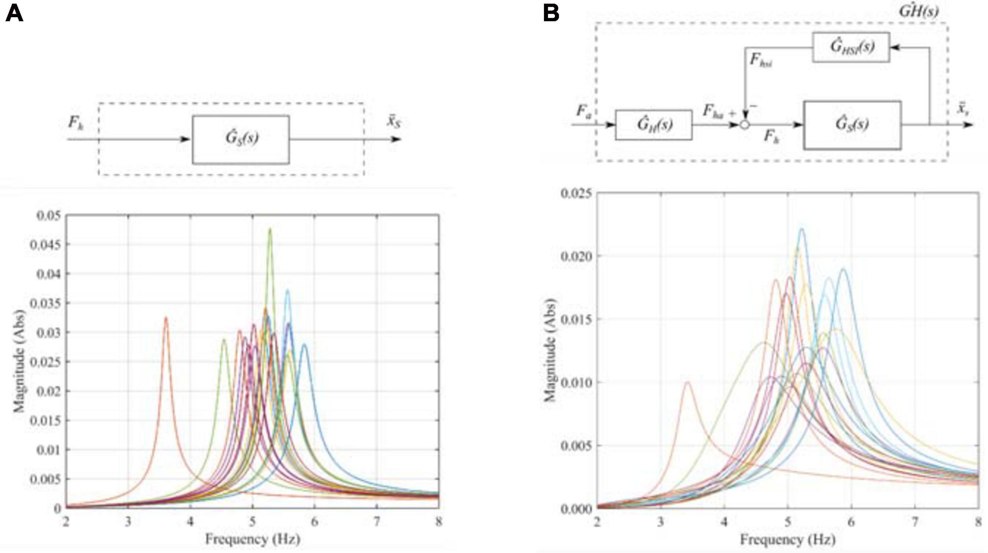
Figure 6. Systems with uncertainties: (A) Block diagram and magnitudes of the TFs of 20 models of the plant, and (B) Block diagram and magnitudes of the TFs of 20 models considering HSI.
HSI Model
HSI phenomenon is modeled for people bouncing at mid-span of the FRP footbridge. As this is the most responsive point of the structure, actions of the humans and the inertial controllers (explained in Section “Controllers Design”) are studied at this location. Bouncing is the considered human-induced load because it enables to derive a time-invariant TF for the coupled human-structure system. Furthermore, the dynamic behavior of the structure may be affected by HSI since feet remain in contact with the bridge at any time. Based on Dougill et al. (2006), the nominal parameters of the human body considered in this study are: 66 kg for the mass, 2.3 Hz for the natural frequency, and 25% for the damping ratio.
Similarly to the structure properties, uncertainties in the dynamic parameters of the human body may be considered due to the variability of values reported in literature for people bouncing (Jones et al., 2011). Thus, the following considerations are adopted: (i) the mass of a person follows a Normal distribution μ = 70 kg and COV = 5%, (ii) the frequency of the human body is described by a Uniform distribution between 1.5 Hz and 6.0 Hz, and (iii) the damping ratio a person follows a Uniform distribution between 20 and 50%.
Considering that the statistical distributions of the human body are also mutually independent, 1000 multivariate stochastic samples are generated using the LH Method. Each human model is associated to a structure model, generating thus 1000 coupled human-structure models (). Figure 6B shows the block diagram of the structure including HSI and uncertainties in the parameters, so and are displayed. For the sake of visualization again, only the magnitudes of the TFs of 20 stochastic systems are presented in this plot.
Validation of the HSI Model
To validate the proposed HSI model, results of the nominal structure-human coupled system (see Eqs. 2, 6–8) are compared with the outcomes of the FE model. One person (N_h1) and two people (Nh2) bouncing at mid-span of the footbridge are studied. To carry out the dynamic analysis in Abaqus (SIMULIA, 2017), the direct integration method HHT-α is employed with a constant time step of 0.001 s and a Rayleigh damping model of 2%. Figures 7A,B show the mass-spring-damper systems that represent each human body in the FE model for the two scenarios of people bouncing synchronously at mid-span. Besides the mass-spring-damper systems, a harmonic force that represents the action of bouncing is used. This action is described as follows
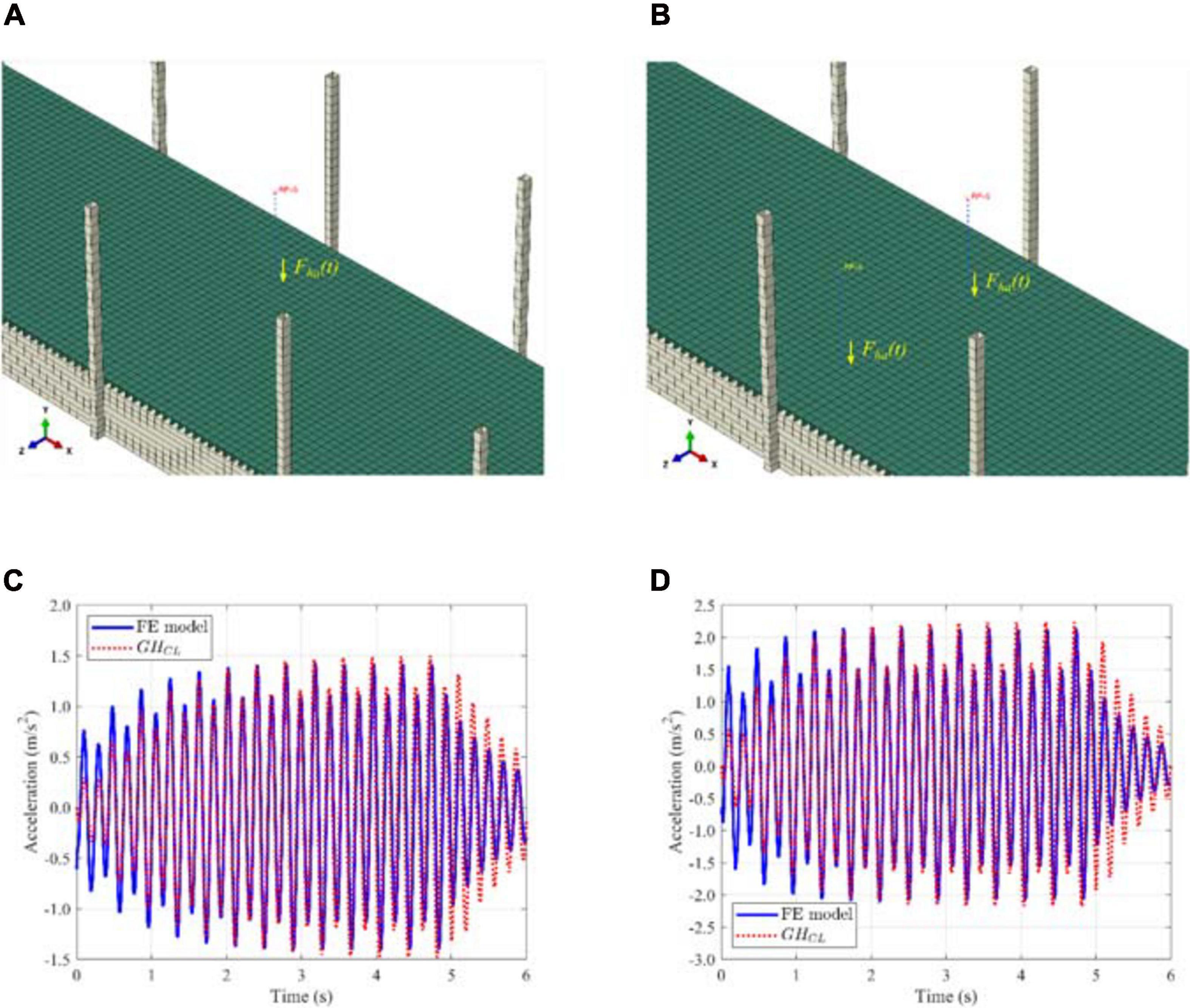
Figure 7. Result comparison: (A) Mass-stiffness-damper system for 1 person, (B) Mass-stiffness-damper systems for 2 people, (C) Time history of the acceleration response for 1 person bouncing, and (D) Time history of the acceleration response for 2 people bouncing.
with k = 1, 2,…Nhar, where Nhar is the number of considered harmonics, Wh is the person’s weight, DLFk is the dynamic load factor for each considered harmonic, f is the frequency component of repetitive loading, and ϕk is the phase angle of the kth harmonic. In this study, DLFs are 0.582, 0.114 and 0.036 for the first three harmonics, respectively, associated to bouncing. The values are obtained from the Generated Load Factors (GLFs), α1 = 0.286, α2 = 0.095, and α3 = 0.033, proposed by Dougill et al. (2006), and the TF presented in Eq. 6.
Figure 7C shows the comparison for the case of one person bouncing. The maximum acceleration from the FE model is 1.44 m/s2, and the obtained result from the GH model is 1.50 m/s2. Figure 7D presents the results for the scenario of two synchronized bouncers, where the peak responses are 2.14 m/s2 (FE model) and 2.23 m/s2 (closed-loop model). In both graphs, the structural response of the footbridge is similar using the numerical model (see Section “Finite Element Model”) and the simplified model (see Eq. 8). Therefore, the proposed methodology is assumed to be validated, and it will be employed in the next sections to design and discuss results using passive and active controllers.
Controllers Design
In this section, the TVA and AVA systems are designed for the FRP footbridge using the TFs presented in Sections “Tuned Vibration Absorber” and “Active Vibration Absorber.”
TVA Design
The design of the TVA is carried out using a single-objective optimization procedure. H norm of the TF of the nominal system, without and with HSI, is chosen as the objective function to be minimized by means of a metaheuristic technique. In this work, a single-objective Genetic Algorithm (GA), which is provided by a toolbox of MATLAB (Mathworks, 2019), is employed for the TVA design in the two cases.
The inertial mass of the device is assumed to be 30.4 kg for both scenarios. This value is preselected because the AVA studied and described in Section 3.7 presents the same inertial mass. For the frequency and damping ratio of the passive controller, a search domain is established in both cases as follows: ft = [4.20−6.20] Hz, and ζt = [0.02,0.12]. Hence, every individual of the population is a vector that contains two variables. Finally, the population size and the maximum number of generations or iterations are set to 50. The design in each scenario is described in the next subsections.
TVA Without HSI
In this case, the mentioned optimization problem is defined as follows
After performing the optimization using the data stated previously, the obtained parameters for the TVA are ft = 5.11 Hz, and ζt = 11.23%.
TVA With HSI
The optimization problem for this scenario is
The resulting TVA parameters are ft = 5.13 Hz, and ζt = 11.94% after completing the corresponding computation procedure.
TVA Performance
The magnitude of the TFs of GS (Eq. 2), GH (Eq. 8), GCL,T (Eq. 13) and GHCL,T (Eq. 15) are displayed in Figure 8A. From this graph, it is obtained that the H∞ norm of the uncontrolled case is reduced in 26% when HSI is considered. This means that HSI plays an important role in the dynamic response of the plant given the H∞ norm represents the maximum amplitude of the absolute value of the TF and this usually use to assess the vibration performance of controllers for structures subjected to harmonic excitations. The reduction of the norm illustrates indirectly that the vibration of the structure is mitigated when the interaction phenomenon is considered. Regarding the TFs in out-of-resonant frequencies, it can be noticed that the model without HSI presents lower values than the system with HSI.
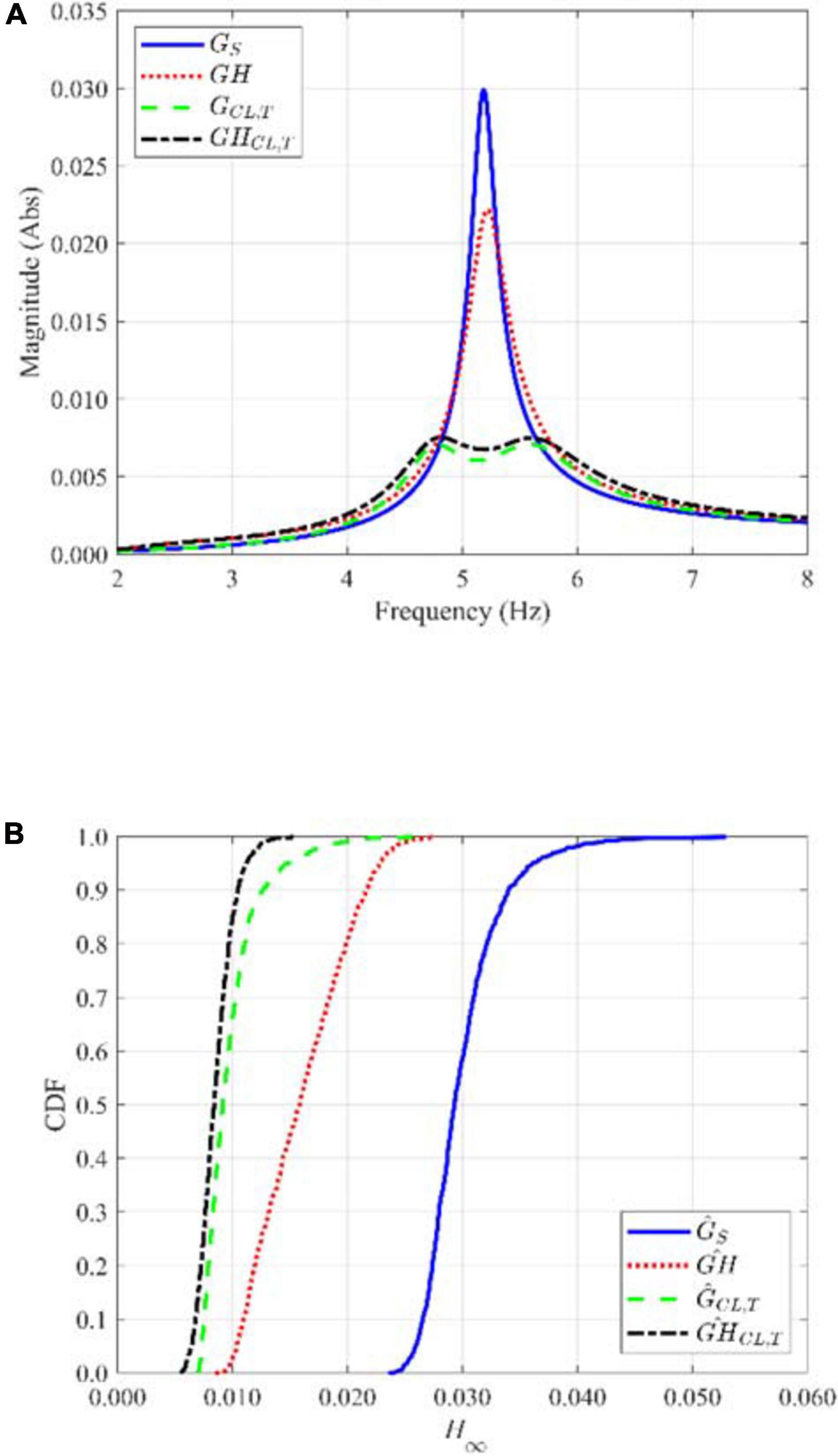
Figure 8. TV A performance: (A) Magnitudes of the TFs for nominal values, and (B) CDF curves due to uncertainties in the systems.
In Figure 8A, it is also depicted that the nominal systems perform quite similarly with the inclusion of the designed TVAs regardless the interaction phenomenon. When uncertainties in the dynamic parameters of the structure and the human body are considered, appreciable differences between the controlled results are observed, as shown in Figure 8B. In this plot, CDF (Cumulative Distribution Function) curves of the H∞ norm for the set of 1000 stochastic samples are presented.
First, the maximum of the H∞ norm values obtained for both controlled systems are compared ( and ). The maximum value of the H∞ norm when HSI is considered decreases 40%, so the influence of HSI may be extremely important when assessing the vibration serviceability of the structure. To assess the reduction for the set of samples, the average of the computed reduction for every stochastic system is calculated. Thus, the following expression is employed
with n = 1, 2,⋯1000. As a result, 67% is the achieved average reduction for the systems without HSI and 44% for the models that include the interaction . This indicates that the inclusion of the TVA is more significant when the interaction phenomenon is neglected. However, it can be seen in Figure 8B that HSI helps to mitigate even more the response of the studied lightweight flexible FRP footbridge.
AVA Design
Four different cases to design an AVA system are tackled next, and the following procedure is adopted for all of them: (i) the root locus technique is employed to illustrate the stability properties of the closed-loop system GCL as a function of the control gain Kv, (ii) guidelines for the selection of the value of Kv are given (controller design problem), and (iii) the resultant TFs are depicted. Also, the following parameters for the proof-mass actuator are used for the simulations: Ke = 160 N/V, ma = 30.4 kg, fa = 2.5 Hz and ζa = 0.35. These correspond to an APS 400 electrodynamic shaker (APS, 2013).
Ideal Actuator Without HSI
In this case, the stiffness and damping of the actuator, along with the internal electrical dynamics have been neglected (perfect control case). Therefore, the actuator TF results in that of an ideal actuator: GA(s) = Ke. Additionally, the ASI and the HSI are also neglected, GAI(s) = 0 (see Figure 3B).
Figure 9A shows the root locus of the resultant system. This diagram shows the location of the poles in the complex plane (defined by the natural frequency and damping ratio) of the closed-loop system when the control gain Kv varies from zero to infinity. As it can be appreciated, the system presents two branches starting at the open loop system poles (). One of them tends to one zero in the origin and the other to one zero in the infinity. The real part of the roots of the system remains negative for all the values of Kv. Thus, the system is unconditionally stable. Moreover, the damping of the closed-loop system increases for increasing values of Kv.
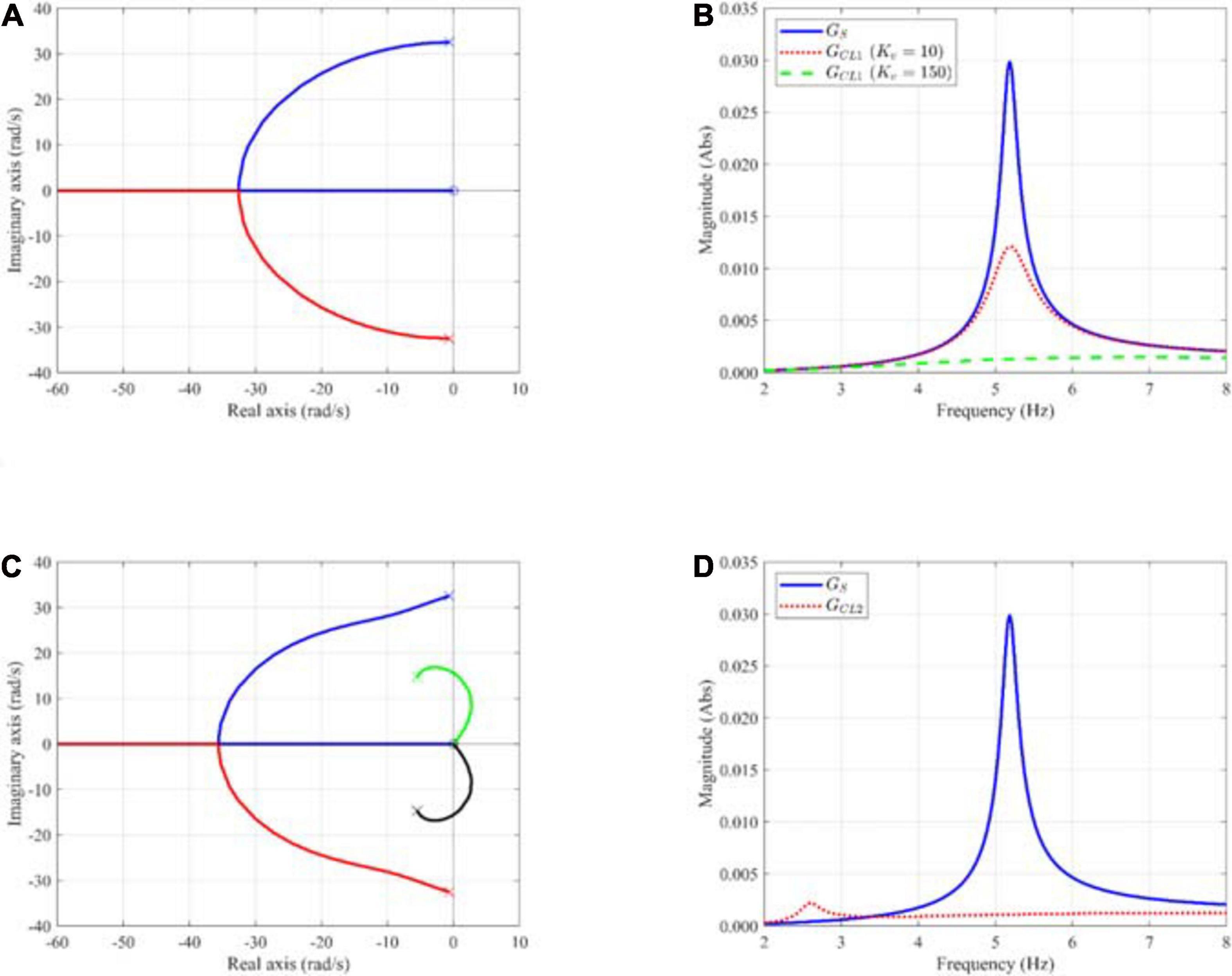
Figure 9. AVA without HSI and ASI: (A) Root locus of an ideal actuator, (B) TFs of an ideal actuator for two control gains (Kv = 10 and Kv = 150), (C) Root locus of a real actuator, and (D) TFs of a real actuator. Symbols: (×) pole, (o) zero.
Since the closed-loop system is unconditionally stable, the root locus diagram does not provide a straightforward criterion to choose the value of the control gain. Consequently, the operational envelope of the proof-mass actuator must be considered to make the selection of Kv. This operational envelope is defined by the kinematic performance limits, that is, maximum achievable displacement (stroke), velocity and acceleration of the moving mass, and the dynamic performance limit, that is, the maximum achievable force by the actuator. The study of the maximum required performances must be carried out considering the actual force acting on the structure and the operational limits imposed to it.
Figure 9B shows the magnitude of the TFs corresponding to the structure, GS, and the closed-loop system for and ideal actuator (case 1), GCL1, with two control gains: Kv = 10 and Kv = 150. The latter value has been chosen according to the analysis carried out in Section “Real Actuator Without HIS.”
Real Actuator Without HSI
In this case, the stiffness and damping of the actuator are considered, so the actuator TF is that shown in Eq. 19. As ASI is ignored, it is considered that the structure motion is negligible in comparison to that of the actuator. As in the previous case, HSI is also neglected.
Figure 9C shows the root locus of the resultant system. In this case, the system presents four branches corresponding to the four system poles. The first two correspond to the structure poles commented in previous case, two low-damped poles. The other pair is associated to the dynamics of the actuator mechanical system and penetrate the right half-plane for increasing values of K_v. This, in turn, corresponds to decreasing the damping associated to this pair of poles. Consequently, the resulting system is conditionally stable and there exists a limit value for the control gain over which the system becomes unstable. That is, the real part of the actuator poles become positive. For the case under study, this limit gain is Kv,lim 195.
A practical criterion to select the control gain is to fix the desired damping for the actuator subsystem in closed loop, so its displacement remains within acceptable limits (Díaz and Reynolds, 2009), avoiding the stroke saturation. In this case, Kv has been selected to yield an actuator damping of 5% (Kv = 150). Figure 9D shows the magnitude of the TFs corresponding to the structure, Gs, and to the closed-loop system (case 2), GCL2, with a control gain Kv = 150. The response of the system is somewhat lower at the structure resonant frequency in comparison with the previous case (Figure 9B) and exhibits a peak near the actuator resonance frequency. The former circumstance is due to the damping effect exerted by the actuator system on the initial structure, while the latter is related to the actuator dynamics and control gain. In effect, as shown in Figure 9C, the damping associated to the actuator poles decreases with increasing values of Kv, with the subsequent increase in its corresponding peak. Hence, the selection of the control gain value should represent a trade-off between overall structural damping and punctual response at the resonant frequency associated to actuator.
Real Actuator Without HSI and With ASI
In this case, HSI is omitted but the full ASI is accounted for (see Eq. 22). Figure 10A shows the root locus of the resultant system. As in the previous case, the system presents four branches. The first pair corresponds to the structure poles. However, the first branch tends to a zero located in the real-negative axis (not in the origin). The second pair corresponds to the mechanical system of the actuator and, as shown before, enters the right-half plane leading to system instability from certain values of Kv on. Nevertheless, in this case, the excursion into the right-half plane takes place for higher values of Kv, leading to an increased stability margin with respect to the previous case. For this case, the theoretical control gain limit value (over which the system becomes unstable) is Kv,lim≈ 250. The control gain value assumed is Kv = 113, which has been calculated to ensure a damping ratio of the actuator of 5% during operation.
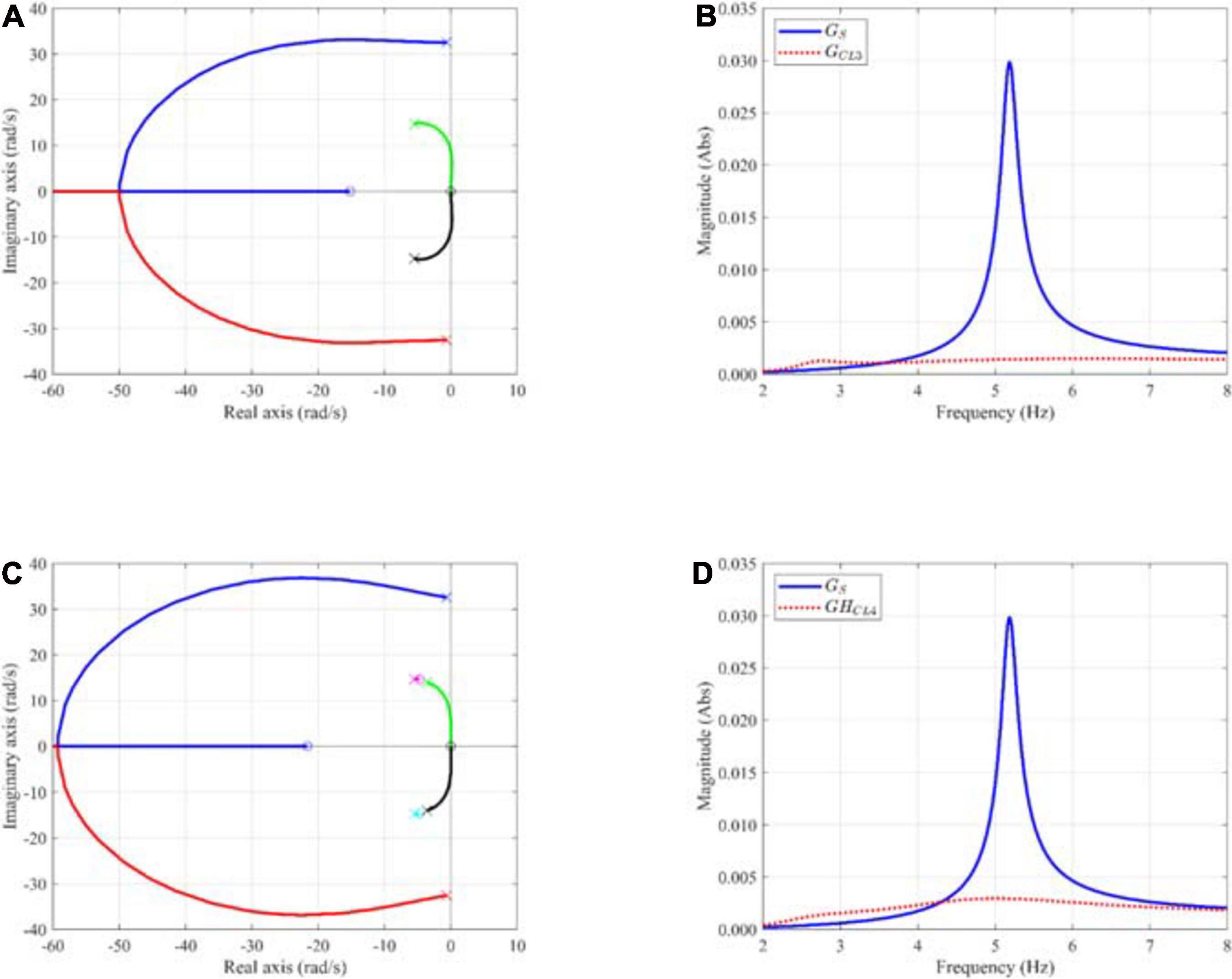
Figure 10. AVA with ASI: (A) Root locus of a real actuator without HSI, (B) TFs of a real actuator without HSI, (C) Root locus of a real actuator with HSI, and (D) TFs of a real actuator with HSI. Symbols: (×) pole, (o) zero.
Figure 10B shows the magnitude of the TFs corresponding to the structure, Gs, and the closed-loop system, GCL3, with the selected control gain. The achieved response, in comparison of that of the previous case, is lower at the structure resonant frequency and at the resonance corresponding to the actuator system. The former stabilizing effect can be thought of as similar to the damping effect due to the HSI previously described. The explanation of the latter effect has been given in previous subsection. It must be carefully addressed since it may lead to a higher response than of the uncontrolled structure for certain (low) frequencies.
Real Actuator With HSI and ASI
In this case, the real actuator along HSI and ASI are considered (see Eq. 23). Figure 10C shows the root locus of the resultant system. The diagram is similar to the one shown in Figure 10A with the difference that two new branches, corresponding to the human-mechanical system appear. Similarly, as in previous case, the branches of the root locus corresponding to the actuator enter the right-half plane, leading to system instability from certain values of K_v on. Again, the excursion into the right-half plane takes place for higher values of K_v, leading to an increased stability margin with respect to the previous case. For this case, the theoretical control gain limit value, over which the system becomes unstable, is Kv,lim 295, and the control gain selected is Kv 59 to ensure a damping ratio of the actuator system of 5%. As it can be appreciated, the value of the gain to achieve a constant damping has decreased as interaction phenomena is considered.
Figure 10D shows the TFs corresponding to the structure G_S, and the complete closed-loop system GHCL4, with the selected control gain. The response achieved for GHCL has deteriorated in comparison to previous cases since a lesser damping force is exerted by the actuator because of the lower control gain. Additionally, a certain amplification takes place at low frequencies due to the modifying effect of the G_H in the surroundings of the human resonant frequency.
AVA Performance
Figure 11A gathers the TFs of the systems GS (see Eq. 2), GH (see Eq. 8), GCL (see Eq. 22) and GHCL (see Eq. 23). The control gain adopted for GCL is 113 (Section “Real Actuator Without HSI and With ASI”), whereas it is 59 for GHCL (Section “Real Actuator With HSI and ASI”).
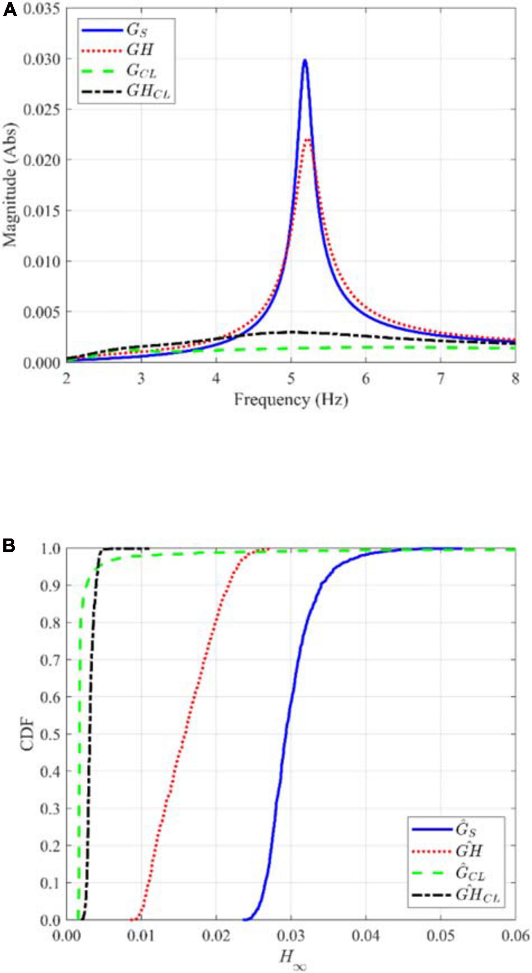
Figure 11. AVA performance: (A) TFs for nominal values, and (B) CDF curves due to uncertainties in the systems.
Figure 11B depicts the CDFs for the different systems (uncontrolled and controlled) with uncertainties. The overall reduction of the H∞ norms for the set of stochastic samples is obtained as explained in Subsection “TVA Performance” (see Eq. 27). The computed average reductions are 91% without HSI and 78% with HSI. However, for the system, 4 cases out of the 1000 present values higher than 0.053, which is the maximum H∞ norm for the uncontrolled case. Additionally, from the CDFs, it can be seem that that AVA is robust to system uncertainties since it achieves similar reductions independently of the stochastic case.
Finally, the reduction values obtained for the different systems including the TVA (see Section “TVA Performance”) and the AVA are collected in Table 2. The incorporation of the latter in the studied FRP footbridge leads to a much larger overall reduction of the H∞ norm.
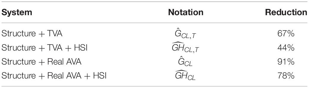
Table 2. Reduction of H∞ norm considering uncertainties.
Discussion
In this section, another laboratory FRP footbridge is studied to discuss the implications of HSI in the design of inertial controllers. The plant, described in Russell et al. (2019), is a pedestrian lively structure, which dynamic properties for the first three modes of vibration (natural frequencies below 10 Hz) are presented in Table 3. For the design procedure of the passive and active controllers (see Section “Controllers Design”), the 1st vibration mode is intended to be controlled and 1 person bouncing at mid-span is the considered human load.
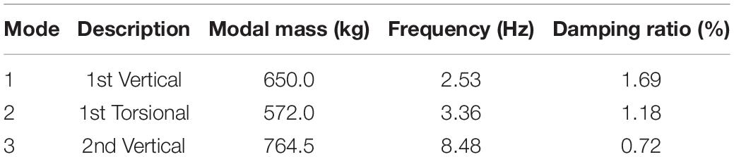
Table 3. Dynamic properties of the first three vibration modes of a laboratory FRP footbridge (Russell et al., 2019).
Following Eqs. 25 and 26, a TVA system is designed to control the excessive vibrations of the plant omitting and considering HSI. As a result, the parameters of the controller are ft = 2.48 Hz, and ζt = 11.97% when HSI is neglected. Whereas ft = 2.55 Hz, and ζt = 11.92 are the designed values of the passive device by accounting the interaction phenomenon. In both cases, mt = 30.4 kg, as explained in Section “TVA Design.”
To assess the performance of the designed TVAs, without and with HSI, it is considered that the first three modes of vibration (Ns = 3) are excited by the human load. Also, two people bouncing synchronously at mid-span (Np = 2) are assumed. Figure 12A presents the time history of the acceleration response of the uncontrolled plant omitting and considering HSI. For Gs model, the maximum response is 32.81 m/s2, and the peak result is 3.50 m/s2 for GH model. As expected, the dynamic response of the plant is unrealistic when the properties of the human body are not considered.
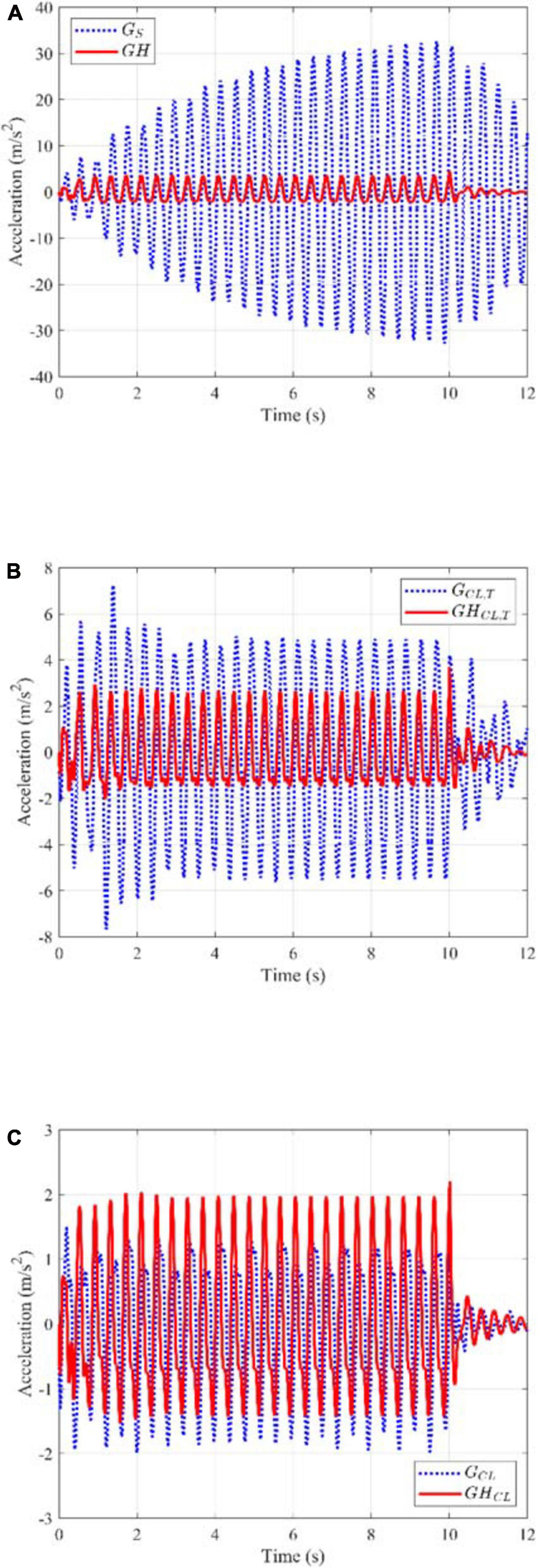
Figure 12. Time history of acceleration response due to two people bouncing without and with HSI: (A) Uncontrolled plant, (B) Plant with a TVA system, and (C) Plant with an AVA system.
In Figure 12B, the acceleration response of the coupled systems, GCL,T (see Eq. 13) and GHCL,T (see Eq. 14), are displayed. In both models, the peak response is reduced with the inclusion of the TVA. In steady state response, a larger reduction of the peak acceleration (5.38 m/s2) is achieved when HSI is not considered (around 84%). However, omitting interaction phenomenon leads to overestimate the maximum acceleration in more than twice the real value (2.65 m/s2), which is given by the human-structure-controller coupled system.
The AVA system has been designed for the cases considering and neglecting HSI in accordance with the root locus procedure explained in Sections “Real Actuator Without HSI and With ASI” and “Real Actuator With HSI and ASI” respectively. Therefore, the control gains have been chosen to achieve a damping ratio of the poles corresponding to the proof mass actuator of around 5%. The control value gains selected for both cases are Kv,nohsi = 43 Vs/m and Kv,hsi = 20. The performance of the AVA system has been evaluated in the same manner as described above for the TVA: three modes of vibration and two people bouncing synchronously at mid-span of the structure.
Figure 12C shows the acceleration response of the systems GCL (see Eq. 22) and GHCL (see Eq. 23). When HSI phenomenon is not considered, a peak response of 1.91 m/s2 is attained in steady state, which represents a reduction of 94 % approximately. On the other hand, when HSI is considered, the peak response is 1.97 m/s2 implying a reduction of 44% with respect to the uncontrolled case accounting for HSI phenomenon.
Conclusion and Future Perspective
This paper takes a coupled human-structure model, which is convenient for practical applications, and studies theoretically and numerically the interaction phenomena (in the frequency domain) presented when dealing with the control of human-induced vibration in very lightweight structures. Thus, inertial passive (TVA) and active (AVA) strategies have been studied without and with the consideration of HSI and ASI applied to an all-FRP lightweight footbridge. Deterministic and stochastic analyses have been carried out in order to draw overall conclusions about the control performance under uncertainty conditions.
From the analysis of the uncontrolled structure without and with HSI, an overall reduction of almost 50% is achieved for the open-loop structures when the HSI is accounted for. This point may be of great importance when assessing the vibration serviceability.
Regarding the TVAs, the design parameters (obtained from the optimization of the H∞ norm of the closed-loop TF) are similar when considering or not the HSI, for the structure studied in this paper (in which the human and structure dynamics are well-separated). Additionally, the overall reduction for the case with HSI is higher than the one obtained without considering HSI. Interestingly, it can be seen that the dynamic amplification factor out of resonance is slightly higher when HSI is considered for structure in hands.
Regarding the AVA, the following conclusions can be drawn:
• When an ideal actuator is used, the system is unconditionally stable and the control gain can be increased infinitely, and the higher the control gain is, the higher damping for the structure is achieved. However, when the actuator dynamics and/or interaction phenomena are included, the system is no longer unconditionally stable. Hence, the control gain has to be chosen carefully to assure system stability and to avoid actuator saturations.
• Assuming the same control gain selection rule (keeping a value of the actuator damping), the control gain decreases as actuator dynamics, HSI and/or ASI are considered. Consequently, the performance of the AVA degrades at the structure’s resonance.
• The selection of the control gain is a trade-off between control reduction at the structure resonance and the dynamic amplification at the actuator resonance.
To sum up, this paper has set the general control strategy including interaction phenomena for the human-induced vibration control on lightweight structures. Undoubtedly, the paper has presented a frequency-domain framework to be used for designers in the integration of vibration control devices in lightweight pedestrian structures susceptible to suffer from interaction phenomena.
Future imminent works will consider a complete sensitivity analysis for a range of multi-mode structures including structural and human uncertainties. These uncertainties may affect the performance of a controller designed for a nominal plant, thus, cases involving this issue must be studied.
Data Availability Statement
The raw data supporting the conclusions of this article will be made available by the authors, without undue reservation.
Author Contributions
ID: project administration, funding acquisition, supervision, conceptualization, methodology, investigation, and writing—review. CG: investigation, software (passive control part), validation, and writing—original draft preparation. JR: investigation, software (active control part), validation, and writing—original draft preparation. CR: investigation, conceptualization, and writing—review. All authors contributed to the article and approved the submitted version.
Funding
This study was supported by the Research Project SEED-SD RTI2018-099639-B-I00, Ministry of Science, Innovation and Universities (Government of Spain).
Conflict of Interest
The authors declare that the research was conducted in the absence of any commercial or financial relationships that could be construed as a potential conflict of interest.
Acknowledgments
The authors acknowledge the financial support provided by the Ministry of Science, Innovation and Universities of Spain through the project “Structural efficiency enhancement for bridges subjected to dynamic loading: integrated smart dampers.” CG expresses his gratitude to the Secretariat of Higher Education, Science, Technology and Innovation of Ecuador (SENESCYT) for the PhD scholarship CZ02-000167-2018. CR thanks Universidad Politécnica de Madrid for the financial support through a PhD research grant.
References
Ahmadi, E., Caprani, C., Živanović, S., and Heidarpour, A. (2019). Assessment of human-structure interaction on a lively lightweight GFRP footbridge. Eng. Struct. 199:109687. doi: 10.1016/j.engstruct.2019.109687
APS. (2013). APS 400 ELECTRO-SEIS§–Long Stroke Shaker with Linear Ball Bearings. San Juan Capistrano, CA: APS Dynamics Inc.
Ascione, L., Caron, J.-F., Godonou, P., van IJselmuijden, K., Knippers, J., Mottram, T., et al. (2016). Prospect for New Guidancein the Design of FRP, Report number: EUR 27666 EN. Ispra: Publications Office of the European Union, doi: 10.2788/22306
Bleicher, A., Schlaich, M., Fujino, Y., and Schauer, T. (2011). Model-based design and experimental validation of active vibration control for a stress ribbon bridge using pneumatic muscle actuators. Eng. Struct. 33, 2237–2247. doi: 10.1016/j.engstruct.2011.02.035
Boniface, V., Bui, V., Bressolette, P., Charles, P., and Cespedes, X. (2006). Footbridges: Assessment of vibrational behaviour of footbridges under pedestrian loading. Paris: Service d’Études Techniques des Routes et Autoroutes, doi: 10.1051/matecconf/201821110002
Caetano, E., Cunha, Á, Moutinho, C., and Magalhães, F. (2010). Studies for controlling human-induced vibration of the Pedro e Inês footbridge, Portugal. Part 2: implementation of tuned mass dampers. Eng. Struct. 32, 1082–1091. doi: 10.1016/j.engstruct.2009.12.033
Casado, C. M., Díaz, I. M., de Sebastián, J., Poncela, A. V., and Lorenzana, A. (2013). Implementation of passive and active vibration control on an in-service footbridge. Struct. Control Heal. Monit. 20, 70–87. doi: 10.1002/stc.471
Casciati, F., Casciati, S., and Faravelli, L. (2017). A contribution to the modelling of human induced excitation on pedestrian bridges. Struct. Saf. 66, 51–61. doi: 10.1016/j.strusafe.2017.01.004
CEN. (2020). prEN 1991-2:2020: Working Document: Actions on Structures - Part 2: Traffic loads on Bridges. Brussels: European Committee for Standardization.
Díaz, I. M., Pereira, E., Hudson, M. J., and Reynolds, P. (2012a). Enhancing active vibration control of pedestrian structures using inertial actuators with local feedback control. Eng. Struct. 41, 157–166. doi: 10.1016/j.engstruct.2012.03.043
Díaz, I. M., Pereira, E., and Reynolds, P. (2012b). Integral resonant control scheme for cancelling human-induced vibrations in light-weight pedestrian structures. Struct. Control Heal. Monit. 19, 55–69. doi: 10.1002/stc.423
Díaz, I. M., and Reynolds, P. (2009). Robust saturated control of human-induced floor vibrations via a proof-mass actuator. Smart Mater. Struct. 18:125024. doi: 10.1088/0964-1726/18/12/125024
Dougill, J. W., Wright, J. R., Parkhouse, J. G., and Harrison, R. E. (2006). Human structure interaction during rhythmic bobbing. Struct. Eng. 118, 32–39.
Elias, S., and Matsagar, V. (2017). Research developments in vibration control of structures using passive tuned mass dampers. Annu. Rev. Control 44, 129–156. doi: 10.1016/j.arcontrol.2017.09.015
Fiberline Composites A/S. (2018). General Design Certification. Middelfart: Fiberline Composites A/S.
Heinemeyer, C., Butz, C., Keil, A., Schlaich, M., and Goldack, A. (2009). Design of Lightweight Footbridges for Human Induced Vibrations. Brussels: European Commission, doi: 10.2788/33846
ISO. (2012). ISO 10137–Bases for Design of Structures–Serviceability of Buildings and Walkways Against Vibrations. Geneva: International Organization for Standardization.
JCSS. (2001). JCSS Probabilistic Model Code. Available online at: https://www.jcss-lc.org/jcss-probabilistic-model-code/ (Accessed June 4, 2020)
Jones, C. A., Reynolds, P., and Pavic, A. (2011). Vibration serviceability of stadia structures subjected to dynamic crowd loads: a literature review. J. Sound Vib. 330, 1531–1566. doi: 10.1016/j.jsv.2010.10.032
Mao, Q., and Huang, S. (2019). Design of tuneable vibration absorber by using inertial actuator with proof-mass acceleration feedback. Int. J. Struct. Stab. Dyn. 19:1950087. doi: 10.1142/S0219455419500871
Mao, Q., Li, S., and Huang, S. (2020). Inertial actuator with virtual mass for active vibration control. Int. J. Acoust. Vib. 25, 445–452. doi: 10.20855/ijav.2020.25.31681
Moreu, F., Maharjan, D., Zhu, C., and Wyckoff, E. (2020). Monitoring human induced floor vibrations for quantifying dance moves: a study of human–structure interaction. Front. Built Environ. 6:36. doi: 10.3389/fbuil.2020.00036
Moutinho, C., Cunha, Á, Caetano, E., and de Carvalho, J. M. (2018). Vibration control of a slender footbridge using passive and semiactive tuned mass dampers. Struct. Control Heal. Monit. 25:e2208. doi: 10.1002/stc.2208
Parkhouse, J. G., and Ewins, D. J. (2006). Crowd-induced rhythmic loading. Proc. Inst. Civ. Eng. Struct. Build. 159, 247–259. doi: 10.1680/stbu.2006.159.5.247
Preumont, A. (2002). An Introduction,” in Vibration Control of Active Structures. Dordrecht: Kluwer Academic Publishers, doi: 10.1007/0-306-48422-6_1
Ramos-Moreno, C., Ruiz-Teran, A. M., and Stafford, P. J. (2020). Impact of stochastic representations of pedestrian actions on serviceability response. Proc. Inst. Civ. Eng. Bridg. Eng. 1–43. doi: 10.1680/jbren.19.00050 [Epub ahead of print].
Russell, J. M., Mottram, J. T., Zivanovic, S., and Wei, X. (2019). “Design and performance of a bespoke lively ALL-FRP footbridge,” in Conference Proceedings of the Society for Experimental Mechanics Series, ed. S. Pakzad (Orlando, FL: Springer New York LLC), 125–128. doi: 10.1007/978-3-030-12115-0_16
Shahabpoor, E., Pavic, A., and Racic, V. (2016). Interaction between walking humans and structures in vertical direction: a literature review. Shock Vib. 2016:3430285. doi: 10.1155/2016/3430285
Silva, R., Pimentel, R., and Pavic, A. (2020). “Performance of biodynamic models to represent the action of a pedestrian in the vertical direction,” in Proceedings of the Eurodyn 2020 11th International Conference on Structural Dynamics, Athens, 1824–1834. doi: 10.47964/1120.9147.19289
SIMULIA. (2017). Abaqus 2017 Analysis User’s Guide. Johnston, IL: Dassault Systèmes Simulia Corporation.
Soria, J. M., Díaz, I. M., and García-Palacios, J. H. (2017). Vibration control of a time-varying modal-parameter footbridge: study of semi-active implementable strategies. Smart Struct. Syst. 20, 525–537. doi: 10.12989/sss.2017.20.5.525
Stratford, T. (2012). “The condition of the Aberfeldy Footbridge after 20 years in service,” in Ph D thesis Paper Presented at Structural Faults and Repair 2012, Edinburgh.
Terrill, R., Bäumer, R., Van Nimmen, K., Van den Broeck, P., and Starossek, U. (2020). Twin Rotor Damper for human-induced vibrations of footbridges. J. Struct. Eng. 146:04020119. doi: 10.1061/(asce)st.1943-541x.0002654
Van Nimmen, K., Lombaert, G., De Roeck, G., and Van den Broeck, P. (2017). The impact of vertical human-structure interaction on the response of footbridges to pedestrian excitation. J. Sound Vib. 402, 104–121. doi: 10.1016/j.jsv.2017.05.017
Van Nimmen, K., Verbeke, P., Lombaert, G., De Roeck, G., and Van den Broeck, P. (2016). Numerical and experimental evaluation of the dynamic performance of a footbridge with tuned mass dampers. J. Bridg. Eng. 21:C4016001. doi: 10.1061/(asce)be.1943-5592.0000815
Wang, H., Chen, J., and Nagayama, T. (2019). Parameter identification of spring-mass-damper model for bouncing people. J. Sound Vib. 456, 13–29. doi: 10.1016/j.jsv.2019.05.034
Wang, Y., Brownjohn, J., Dai, K., and Patel, M. (2019). An estimation of pedestrian action on footbridges using computer vision approaches. Front. Built Environ. 5:133. doi: 10.3389/fbuil.2019.00133
Wei, X., Russell, J., Živanović, S., and Toby Mottram, J. (2019). Measured dynamic properties for FRP footbridges and their critical comparison against structures made of conventional construction materials. Compos. Struct. 223:110956. doi: 10.1016/j.compstruct.2019.110956
Zhang, C., and Ou, J. (2015). Modeling and dynamical performance of the electromagnetic mass driver system for structural vibration control. Eng. Struct. 82, 93–103. doi: 10.1016/j.engstruct.2014.10.029
Keywords: vibration control, human-structure interaction, lightweight structures, inertial mass controller, active vibration control
Citation: Díaz IM, Gallegos CA, Ramírez Senent J and Renedo CMC (2021) Interaction Phenomena to Be Accounted for Human-Induced Vibration Control of Lightweight Structures. Front. Built Environ. 7:658529. doi: 10.3389/fbuil.2021.658529
Received: 25 January 2021; Accepted: 24 March 2021;
Published: 12 April 2021.
Edited by:
Onur Avci, Iowa State University, United StatesReviewed by:
Agathoklis Giaralis, City University of London, United KingdomŁukasz Jankowski, Institute of Fundamental Technological Research, Polish Academy of Sciences, Poland
Copyright © 2021 Díaz, Gallegos, Ramírez Senent and Renedo. This is an open-access article distributed under the terms of the Creative Commons Attribution License (CC BY). The use, distribution or reproduction in other forums is permitted, provided the original author(s) and the copyright owner(s) are credited and that the original publication in this journal is cited, in accordance with accepted academic practice. No use, distribution or reproduction is permitted which does not comply with these terms.
*Correspondence: Iván M. Díaz, aXZhbi5tdW5vekB1cG0uZXM=