
94% of researchers rate our articles as excellent or good
Learn more about the work of our research integrity team to safeguard the quality of each article we publish.
Find out more
ORIGINAL RESEARCH article
Front. Built Environ., 15 March 2021
Sec. Earthquake Engineering
Volume 7 - 2021 | https://doi.org/10.3389/fbuil.2021.656606
This article is part of the Research TopicSmart Passive Damper Design for Building Structures with Higher Resilience Under Uncertain Earthquake Ground MotionsView all 8 articles
 Soichiro Ishida
 Izuru Takewaki*
The viscous-hysteretic hybrid (HVH) damper system recently introduced by one of the authors has a clear property that, when the hysteretic dampers with gap mechanism become active (stiffness element starts working), the acceleration of building frames with this damper system as a stopper attains large values in spite of the advantageous feature to prevent excessive deformation. It is therefore desired that both the maximum interstory drift and the maximum acceleration exhibit an acceptable value with appropriate compromise. The double impulse as a simplified version of one-cycle sine wave as a representative of the main part of near-fault ground motions can simulate the maximum interstory drifts properly. However, it cannot simulate the maximum accelerations due to its impulsive nature. In this case, the sine wave corresponding to the double impulse can play an important role in the reliable simulation of the maximum accelerations. Even in such circumstance, the analysis using the double impulse is important because it enables to obtain the critical timing of the input, i.e. the nonlinear resonant frequency of the sine wave without repetition. The investigations on the criticality of the sine wave corresponding to the critical double impulse show that the critical timing of the double impulse leads to the nonlinear resonant frequency of the sine wave in view of the maximum interstory drift, the maximum top acceleration and the maximum relative acceleration for the constant input acceleration and the constant input velocity except for some cases. It is demonstrated finally that the index in terms of the maximum interstory drift and the maximum acceleration can be introduced as an appropriate parameter for deriving the optimally compromised gap quantity of hysteretic dampers with gap mechanism for various input velocity levels and various hysteretic damper stiffness ratios.
Recently, “resilience” is becoming a principal target of structural and infrastructural design in the world that faces rapidly‐changing natural hazard risks. Various methods and strategies have been proposed for upgrading the resilience performance from several different viewpoints. Bruneau et al. (2003) introduced the concept of resilience in the field of structural engineering for the first time and provided the so-called “resilience triangle”. Cimellaro et al. (2010) quantified the resilience in the framework of the resilience triangle. Takewaki et al. (2011) explained the significance and effectiveness of structural control in the upgrade of the resilience. Noroozinejad et al. (2019) focused on the review of the concept of resilience in the structural and infrastructural engineering. In the usual framework, the resistance to risks and the recovery from damaged states after disturbances are defined as two main phases in the resilience. The past history in the structural and infrastructural design indicated that, while the resistance has been treated as a main research field, the recovery has never been tackled satisfactorily due to various complicated factors related to multidisciplinary fields.
In place of the structural design philosophy to withstand earthquake and wind disturbances by the reasonable proportioning of member stiffness and strength, structural control has been introduced worldwide. The overall advances of structural control in each period are summarized in the literatures. Hanson (1993) and Aiken et al. (1993) pointed out the importance of introducing passive dampers in the structural design of buildings. Soong and Dargush (1997) and Hanson and Soong (2001) explained the properties of passive dampers and summarized the state of the arts up until around 2000. Takewaki (2009) and Lagaros et al. (2013) presented several design methods of passive dampers and summarized the development up until around 2010. After sufficient development of various passive damper systems, smart and optimal design (quantity and location) of passive dampers is becoming one of the main topics in the field of structural control. Various approaches to the design of linear and nonlinear viscous dampers have been developed. Aydin et al. (2007) extended the transfer function amplitude approach in terms of interstory drifts due to Takewaki (1997) (the unified formulation is shown in Takewaki (2009)) to base shears. Attard (2007) developed a gradient-based optimization algorithm for highly nonlinear degrading steel frames. Lavan and Levy (2010) presented another gradient-based method of optimal seismic retrofitting for yielding plane frames with viscous dampers by using an optimal control theory. Adachi et al. (2013) devised a unique gradient-based sequential algorithm for determining the optimal nonlinear viscous damper location and quantity in linear building frames. Akehashi and Takewaki (2019) used the critical excitation approach for the optimal viscous damper placement in elastic-plastic shear building structures to consider input uncertainties. In particular, a complete survey on the research of viscous dampers can be found in the review paper (De Domenico et al., 2019). While viscous dampers are faced with a cost problem, hysteretic dampers, e.g. buckling-restrained braces, have often been employed in earthquake prone countries. At the same time, simultaneous use of various types of dampers has been sought.
As for damper design methods, some useful investigations were conducted. The followings are some examples. Silvestri et al. (2010) and Palermo et al. (2016); Palermo et al. (2017); Palermo et al. (2018) proposed a practical design method of linear and nonlinear viscous dampers for linear building frames. Their methods consist of five steps. Its design philosophy is based on the limit of the structural damages under severe earthquakes. A target response reduction factor is chosen first for satisfying the condition on the desired reduction of the peak structural response. The equivalent linear viscous damping coefficients for nonlinear dampers are computed by using effectively the properties of modal damping ratios as classically damped systems. Elias and Mastsagar (2019) dealt with nonlinear frame responses using multiple TMD optimization. Although single TMD is effective for the control of linear frames, multiple TMDs were devised for controlling nonlinear frame responses. De Domenico and Ricciardi (2019) investigated an optimization problem of nonlinear viscous dampers used in building frames. The nonlinear power law in the constitutive relation of the devices was introduced in the optimal design process. Tabara and De Domenico (2020) investigated the design of nonlinear viscous dampers. They transformed the nonlinear viscous dampers into the equivalent linear model and enabled the application of the response spectrum method in the seismic response evaluation for sophisticated damper design.
While linear viscous dampers have been treated in the framework of linear formulation, the design of hysteretic dampers necessitates distinct kinds of treatment due to their peculiar characteristics. Murakami et al. (2013) introduced a relaxed and stabilized sensitivity-based approach applicable to hysteretic dampers. Numerical optimization algorithms including time-history response analysis for response evaluation are needed for taking into account these peculiar characteristics in hysteretic dampers. The algorithm including time-history response analysis requires a tremendous amount of computational effort to disclose original properties of the optimal damper location and quantity. In comparison with such conventional approaches, an innovative design method was developed by Shiomi et al. (2016) for hysteretic dampers. In this method, an explicit expression was taken full advantage for the maximum elastic-plastic response of a single-degree-of-freedom (SDOF) system with hysteretic dampers under “the critical double impulse” as a representative of near-fault ground motions (Kojima and Takewaki 2015). Then a direct and simple optimization was implemented using this explicit expression. Subsequently, Shiomi et al. (2018) proposed a novel control system called a “dual hysteretic damper (DHD)” system and developed a sensitivity-based optimal design method of damper placement for multi-degree-of-freedom (MDOF) systems. Recently, Hashizume and Takewaki (2020a); Hashizume and Takewaki (2020b) proposed another new vibration control system called a “hysteretic viscous hybrid (HVH)” damper system by replacing the DSA (short-range hysteretic damper) in the DHD system by a viscous damper. They clarified the response reduction performance of the DHD and the HVH for SDOF and MDOF systems.
In this paper, the HVH system introduced by Hashizume and Takewaki (2020a); Hashizume and Takewaki (2020b) will be investigated from two main viewpoints (stiffness and functionality). The stiffness can be measured in terms of the maximum interstory drift and the functionality (usability) can be evaluated in terms of the maximum acceleration. The HVH damper system consisting of viscous dampers and hysteretic dampers with gap mechanism has a clear property that, when the hysteretic dampers with gap mechanism become active (stiffness element starts working), the acceleration of building frames with this damper system as a stopper attains large values in spite of the advantageous feature to prevent excessive deformation. It is therefore desired that both the maximum interstory drift and the maximum acceleration exhibit an acceptable value with appropriate compromise. The double impulse as a simplified version of one-cycle sine wave as a representative of the main part of near-fault ground motions can simulate the maximum interstory drifts properly. However, it cannot simulate the maximum accelerations due to its impulsive nature. In this case, the sine wave corresponding to the double impulse can play an important role in the reliable simulation of the maximum accelerations. Even in such circumstance, the analysis using the double impulse is important because it can obtain the critical timing of the input, i.e. the nonlinear resonant input frequency of the sine wave without repetition. The investigations on the criticality of the sine wave corresponding to the critical double impulse show that the critical timing of the double impulse leads to the nonlinear resonant frequency of the sine wave in view of the maximum interstory drift except for some cases. A similar property on the criticality is also demonstrated for the maximum top acceleration and the maximum relative acceleration for the constant input acceleration and the constant input velocity. Finally, a new index in terms of the maximum interstory drift and the maximum acceleration is introduced as an appropriate parameter for deriving the optimally compromised gap quantity of hysteretic dampers with gap mechanism.
In the innovative energy approach by Kojima and Takewaki (2015), it was clarified that the property of the main part of a near-fault pulse-type ground motion can be captured by the double impulse. The double impulse has an advantage that it produces only a free-vibration component and the combination of free-vibration component and forced-vibration component is unnecessary. In this approach, the main part of a near-fault ground motion is first expressed by a one-cycle sine wave
where
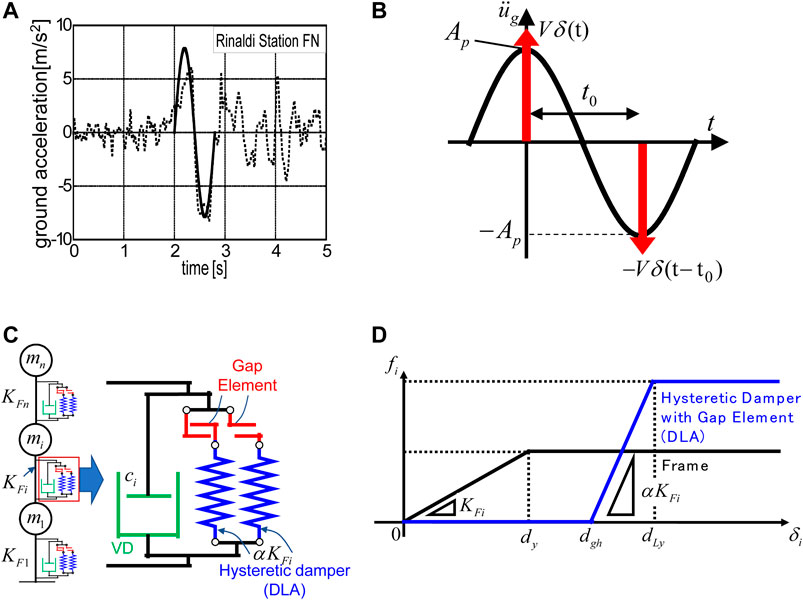
FIGURE 1. Modeling of main part of ground motion into double impulse and passive control system HVH, (A) Transformation of main part of Rinaldi station FN motion (Northridge 1994) into one-cycle sine wave, (B) Transformation into double impulse, (C) Passive control system HVH, (D) Force-deformation relations of frame and hysteretic damper with gap mechanism (Partially from Shiomi et al., 2018 and Hashizume and Takewaki 2020b).
The Fourier transform of Eq. 2 can be expressed as
On the other hand, the Fourier transform of Eq. 1 can be computed by
The Fourier amplitudes of both inputs are expressed by
The ratio
The coefficient
Consider the ratio of the maximum velocity
Eq.8 provides the maximum velocity
Finally, based on the investigation after Eq. 7 (Akehashi et al., 2018; Hashizume and Takewaki 2020b),
Consider a hysteretic-viscous hybrid (HVH) damper system proposed in the recent papers (Hashizume and Takewaki, 2020a; Hashizume and Takewaki, 2020b). The most remarkable property of this damper system is to possess a gap mechanism in the hysteretic damper system and play a role as a stopper system. The gap mechanism gives the system a redundancy to the limit on the accumulated plastic deformation capacity. With this mechanism, the hysteretic damper with a gap mechanism exhibits a large-stroke performance.
A MDOF building structure including the HVH system is shown in Figure 1C. The building structure is modeled as a shear building model and the hysteretic damper is assumed to have the elastic-perfectly plastic restoring-force characteristics. Let
The total story shear strength in the ith story can be expressed by
In this section, the response reduction characteristic of the MDOF system with the HVH system is presented. Especially, the influence of DLA with gap mechanism as a stopper element will be investigated. The structural parameters of the main frame, the viscous damper and the hysteretic damper (DLA) in the MDOF system with the HVH system are shown in Table 1.
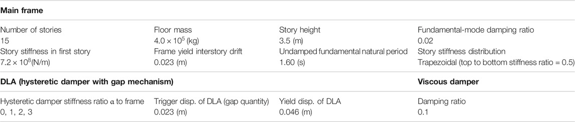
TABLE 1. Structural parameters of main frame, viscous damper and hysteretic damper (HVH system).
The nonlinear time-history response analysis was conducted by using a Newmark-
The critical timing of the second impulse can be obtained by conducting a time-history response analysis under the first impulse and identifying the time attaining the zero value of the story shear force in the first story (Akehashi and Takewaki, 2019).
The double impulse with the input velocity level V = 2.0 (m/s) is considered. The left figures in Figure 2 show the time histories of the first, eighth and 15th-story interstory drifts of 15-story buildings with HVH system for various damper stiffness ratios
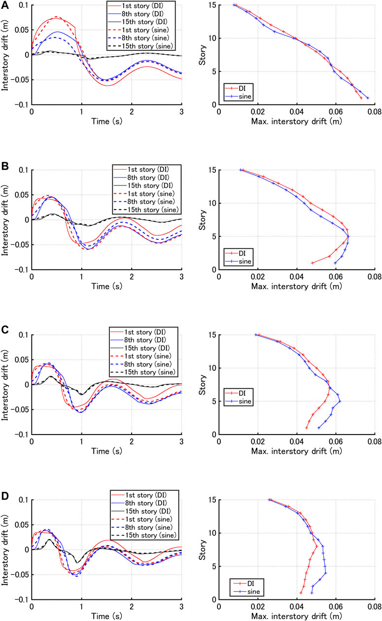
FIGURE 2. Time histories of first, eighth and 15th-story interstory drifts and maximum interstory drift distributions of 15-story buildings with HVH system for three hysteretic damper stiffness ratios
Although the double impulse can simulate the maximum interstory drifts properly, it cannot simulate the maximum accelerations due to its impulsive nature. For this reason, the sine wave corresponding to the double impulse can play an important role in the simulation of the maximum accelerations. However, even in this case, the analysis using the double impulse is important in the sense that it enables to obtain the critical timing of the input, i.e. the nonlinear resonant frequency of the sine wave. This property will be discussed later in more detail.
In this section, the validity of the nonlinear resonant frequency of the sinusoidal wave transformed from the critical double impulse is investigated. The analysis using the double impulse is important because it enables to obtain the critical timing of the double impulse, i.e. the nonlinear resonant frequency of the sine wave without repetition. The investigations on the criticality of the sine wave corresponding to the critical double impulse are conducted in view of the maximum interstory drift, the maximum top acceleration and the maximum relative acceleration for the constant input acceleration and the constant input velocity except for some cases. Eq. 9 is used for realizing the constant input acceleration and the constant input velocity.
Figure 3 shows the maximum interstory drift and top acceleration with respect to input frequency of the sine wave corresponding to the critical double impulse with constant acceleration amplitude for three hysteretic damper stiffness ratios
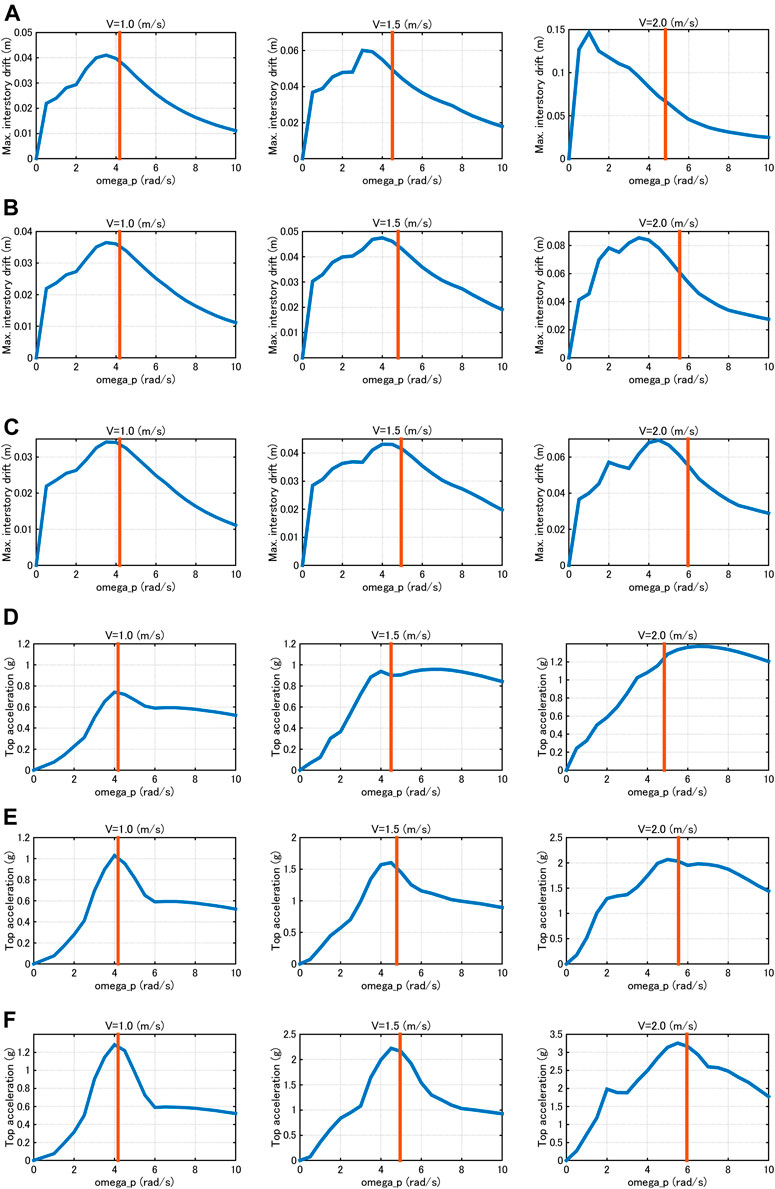
FIGURE 3. Maximum interstory drift and top acceleration with respect to input frequency of sine wave corresponding to critical double impulse with constant acceleration amplitude, (A) Max. interstory drift (m): α = 1, (B) Max. interstory drift (m): α = 2, (C) Max. interstory drift (m): α = 3, (D) Top acceleration: α = 1, (E) Top acceleration: α = 2, (F) Top acceleration: α = 3.
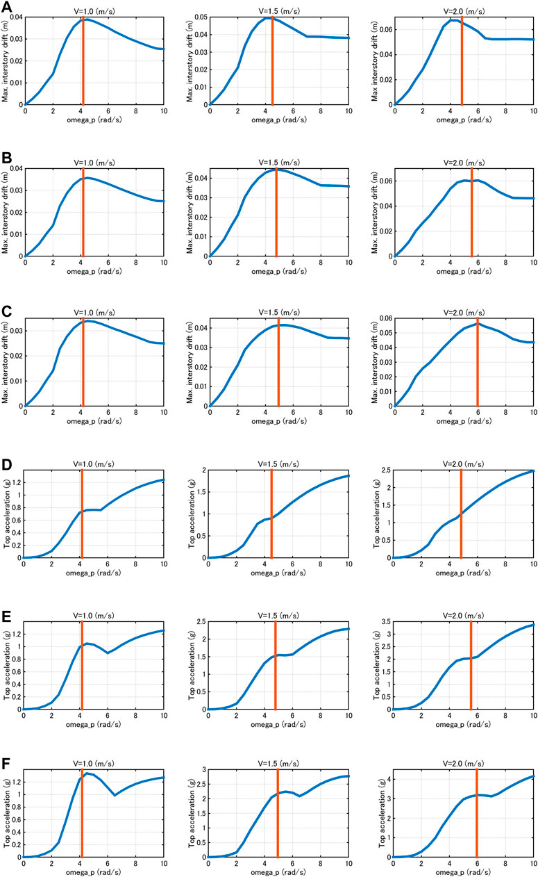
FIGURE 4. Maximum interstory drift and top acceleration with respect to input frequency of sine wave corresponding to critical double impulse with constant velocity amplitude, (A) Max. interstory drift (m): α = 1, (B) Max. interstory drift (m): α = 2, (C) Max. interstory drift (m): α = 3, (D) Top acceleration: α = 1, (E) Top acceleration: α = 2, (F) Top acceleration: α = 3.
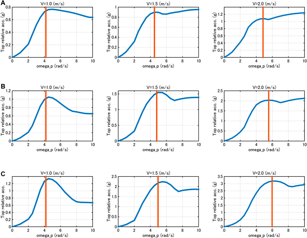
FIGURE 5. Top relative acceleration with respect to input frequency of sine wave corresponding to critical double impulse with constant velocity amplitude, (A) α = 1, (B) α = 2, (C) α = 3.
Figures 3–5 demonstrate that, through the investigations on the criticality of the sine wave corresponding to the critical double impulse, the critical timing of the double impulse leads to the nonlinear resonant input frequency of the sine wave in view of the maximum interstory drift, the maximum top acceleration and the maximum relative acceleration for the constant input acceleration and the constant input velocity except for some cases.
In Sections Hysteretic-Viscous Hybrid Damper System and Responseof Frame with HVH Under Double Impulse and Corresponding Sine Wave and Investigation on Nonlinear Resonant Frequency of Sinusoidal Wave Transformed From Critical Double Impulse, the response characteristics of shear building models with HVH damper systems and its nonlinear resonant frequencies were investigated. In this section, the optimal design of hysteretic dampers with gap mechanism (stiffness and gap quantity) is discussed. Since a simple setting of damper properties (common setting of damper parameters throughout all stories), stiffness ratios and gap quantities of hysteretic dampers are set commonly throughout all stories (
First of all, the optimal stiffness of hysteretic dampers with gap mechanism is searched from the viewpoint of suppression of deformation and acceleration. The parameters except the hysteretic damper stiffness ratio
Figure 6 shows the maximum interstory drift distributions for various hysteretic damper stiffness ratios and the story ductility factors with respect to hysteretic damper stiffness ratio for input velocity levels V = 1.0, 1.5, 2.0 (m/s) under the sine waves corresponding to the critical double impulses. It can be observed that, as the hysteretic damper stiffness ratio becomes larger, the deformation concentration in lower stories is controlled to lower levels. Furthermore, the usage of hysteretic dampers in the elastic range is effective for the control of deformation even for larger input.
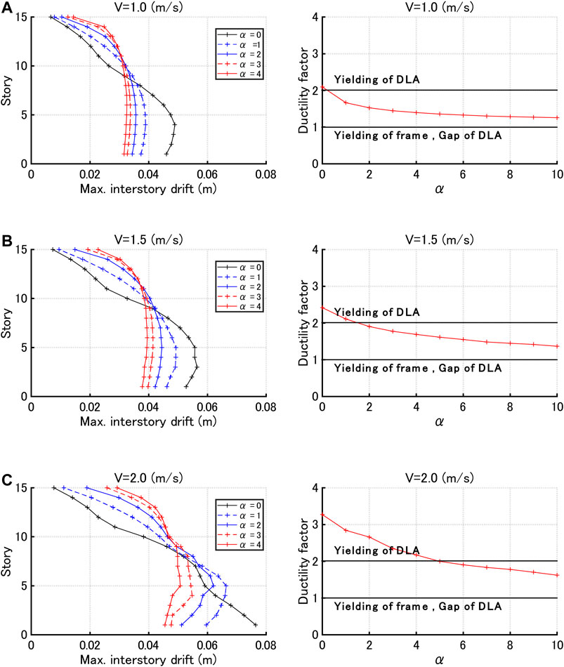
FIGURE 6. Maximum interstory drift distributions for various hysteretic damper stiffness ratios and story ductility factor with respect to hysteretic damper stiffness ratio under sine waves corresponding to critical double impulses with three input velocity levels, (A)V = 1.0 (m/s), (B)V = 1.5 (m/s), (C)V = 2.0 (m/s).
Figure 7 presents the maximum acceleration distributions for various hysteretic damper stiffness ratios and the top acceleration with respect to hysteretic damper stiffness ratio for input velocity levels V = 1.0, 1.5, 2.0 (m/s) under sine waves corresponding to critical double impulses. It can be observed that, as the hysteretic damper stiffness ratio becomes larger, the acceleration distributions become extremely large. This indicates that a compromise of the maximum interstory drift and the maximum acceleration should be considered by selecting an appropriate hysteretic damper stiffness ratio.
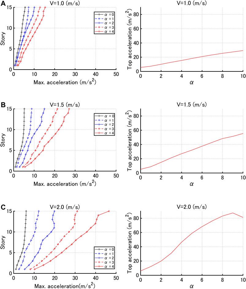
FIGURE 7. Maximum acceleration distributions for various hysteretic damper stiffness ratios and top acceleration with respect to hysteretic damper stiffness ratio under sine waves corresponding to critical double impulses with three input velocity levels, (A)V = 1.0 (m/s), (B)V = 1.5 (m/s), (C)V = 2.0 (m/s).
Figure 8 shows the following three parameters
where
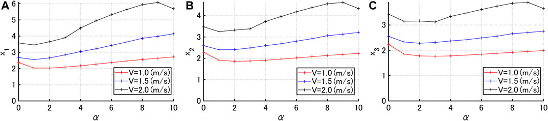
FIGURE 8. Indices
In this section, the gap quantity optimization is conducted. The parameters except the gap quantity
Figure 9 shows the maximum interstory drift distributions for various gap quantities under sine waves corresponding to the critical double impulses with three input velocity levels V = 1.0, 1.5, 2.0 (m/s). It can be observed from Figure 9 that, when the input velocity level is small, the maximum interstory drifts in lower stories become larger for the increasing trigger level of hysteretic dampers (gap quantity) irrespective of
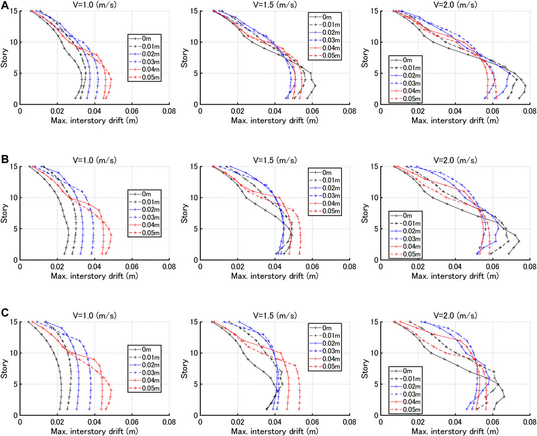
FIGURE 9. Maximum interstory drift distributions for various gap quantities and three hysteretic damper stiffness ratios under sine waves corresponding to critical double impulses, (A) Hysteretic damper stiffness ratio
Figure 10 presents the maximum interstory drift with respect to gap quantity for three input velocity levels V = 1.0, 1.5, 2.0 (m/s). The dotted line indicates the frame yield level. It can be observed that the response exhibits a constant value for the gap larger than a certain value. This is because the maximum interstory drift is smaller than the trigger level of hysteretic dampers (gap quantity) and the hysteretic dampers do not work.
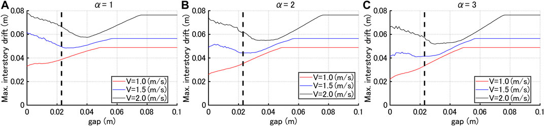
FIGURE 10. Maximum interstory drift with respect to gap quantity for three input velocity levels V = 1.0, 1.5, 2.0 (m/s) and three hysteretic damper stiffness ratios, (A)
Figure 11 illustrates the maximum acceleration distributions for various gap quantities under sine waves corresponding to the critical double impulses with three input velocity levels V = 1.0, 1.5, 2.0 (m/s). It can be observed from Figure 11 that, while the maximum accelerations in lower stories do not change so much for variable gap quantity, those in upper stories are much affected and become smaller as the gap quantity becomes larger.
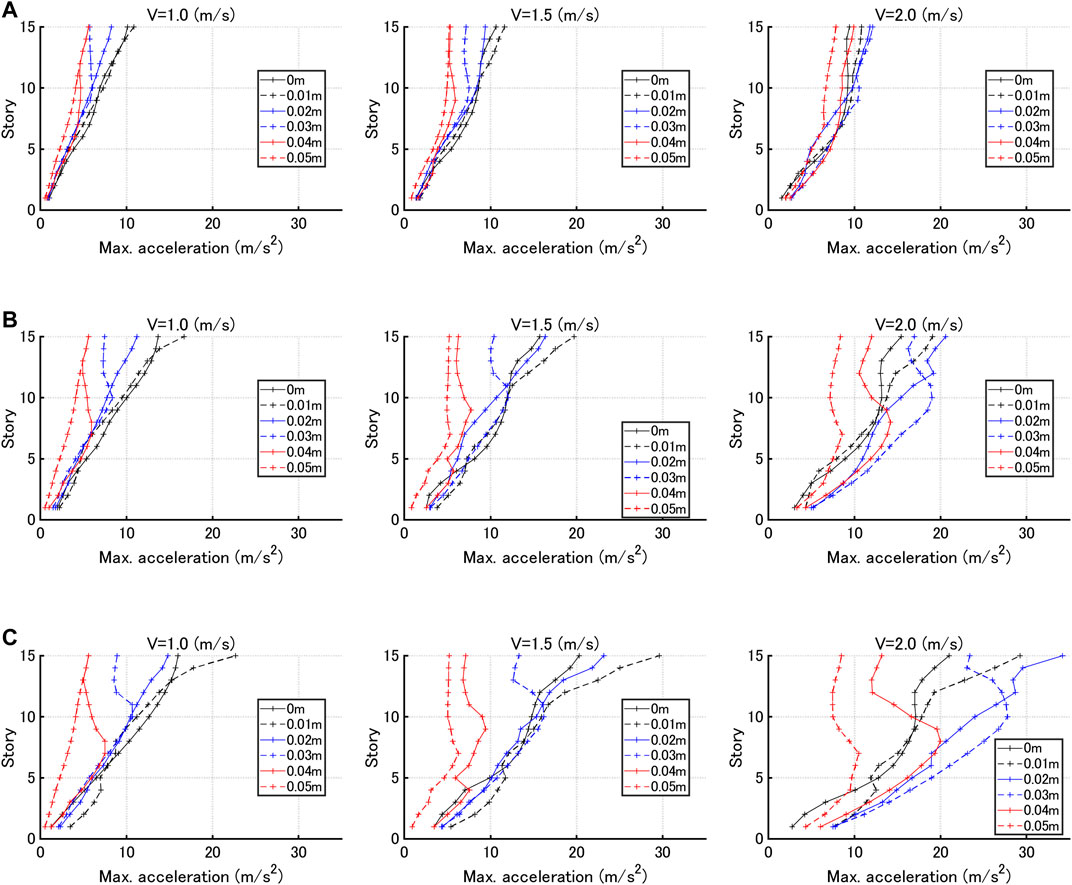
FIGURE 11. Maximum acceleration distributions for various gap quantities under sine waves corresponding to critical double impulses, (A)
Figure 12 shows the top acceleration with respect to gap quantity for three input velocity levels V = 1.0, 1.5, 2.0 (m/s). The dotted line indicates the frame yield level. It can be observed that the acceleration response exhibits a constant value for the gap larger than a certain value. This is because the maximum interstory drift is smaller than the trigger level of hysteretic dampers (gap quantity) and the hysteretic dampers do not work. Furthermore, it is found that, as the gap quantity becomes larger, the top acceleration exhibits a local maximum. From these results, it can be concluded that, when the frame velocity at the working of hysteretic dampers is large, the maximum acceleration becomes large. In addition, it is suggested that the worst selection of the gap quantity giving the maximum acceleration should be avoided.
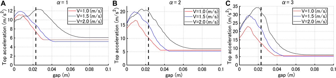
FIGURE 12. Top acceleration with respect to gap quantity for three input velocity levels V = 1.0, 1.5, 2.0 (m/s) and three hysteretic damper stiffness ratios, (A)
Consider the following parameter
where
Figure 13 presents the index
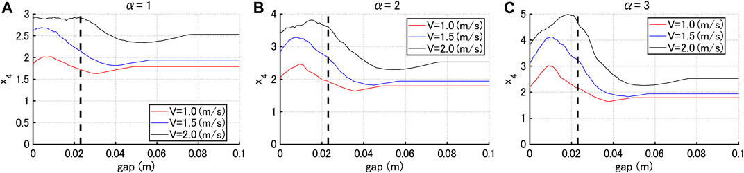
FIGURE 13. Index
Figure 14 demonstrates that the optimal gap quantity vs. input velocity level of the critical double impulse can be derived for various hysteretic damper stiffness ratios. It can be observed that the optimal gap quantity attains almost the same value for the input velocity level independent of
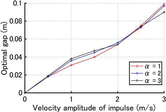
FIGURE 14. Optimal gap quantity vs. input velocity level of critical double impulse for three hysteretic damper stiffness ratios
The investigation on the effect of damping coefficients of viscous dampers in the HVH control system was conducted in the previous paper (Hashizume and Takewaki, 2020b), although only the maximum interstory drifts were treated as the response parameters. It was concluded that the increase of the damping quantity of viscous dampers is effective for the suppression of the maximum interstory drifts. On the other hand, the yielding displacements (without gap quantity) of hysteretic dampers were not investigated because a fixed-type hysteretic damper is assumed to be used. However, it was pointed out that the design of hysteretic dampers so as to attain just the yield point when the frame reaches the maximum interstory drifts is a preferable design leading to the minimum interstory drift.
It seems important to investigate the response to pulse-type recorded ground motions with large amplitude. This investigation was conducted in the previous paper (Hashizume and Takewaki, 2020b), although only the maximum interstory drifts were treated as the response parameters. It was demonstrated that the HVH control system is effective also for pulse-type recorded ground motions with large amplitude. However, it should be remarked that, while only the critical resonant response was dealt with in the double impulse pushover (DIP) analysis, the analysis to recorded ground motions does not necessarily provide the worst scenario. The DIP analysis was proposed by Akehashi and Takewaki (2019). The range of the velocity amplitude of the double impulse is assumed. Then the response to the critical double impulse with the initial velocity amplitude (the smallest one) is computed. This procedure is repeated for various velocity-amplitudes of the double impulse in the assumed range. The plot of the maximum interstory drift with respect to the velocity-amplitude of the double impulse indicates the result of the DIP analysis.
The research on the response characteristics for a broader class of pulse-type recorded ground motions is desired in the future.
The viscous-hysteretic hybrid (HVH) damper system proposed by one of the present authors (Hashizume and Takewaki, 2020b) has a property that, when the hysteretic dampers with gap mechanism become active (stiffness starts working), the acceleration of building frames with this damper system exhibits large values in spite of the advantageous feature to prevent excessive deformation. It is therefore desired that the maximum interstory drift and the maximum acceleration exhibit reasonable values with appropriate compromise. The following conclusions were derived.
(1) The double impulse can simulate the maximum interstory drifts properly under a sine wave as a representative of the main part of near-field ground motions. However, it cannot simulate the maximum accelerations due to its impulsive nature. In this case, the sine wave corresponding to the double impulse can play an important role in the simulation of the maximum accelerations. Even in such circumstance, the analysis using the double impulse is important because it can obtain the critical timing of the double impulse, i.e. the nonlinear resonant frequency of the sine wave.
(2) The investigations on the criticality of the sine wave corresponding to the critical double impulse showed that the critical timing of the double impulse leads to the nonlinear resonant frequency of the sine wave in view of the maximum interstory drift except for some cases. A similar property on the criticality was also demonstrated for the maximum top acceleration and the maximum relative acceleration for the constant input acceleration and the constant input velocity.
(3) The index
(4) The relation of the optimal gap quantity with the input velocity level of the critical double impulse can be derived for various hysteretic damper stiffness ratios. It was confirmed that this relation is approximately independent of the hysteretic damper stiffness ratio.
The raw data supporting the conclusions of this article will be made available by the authors, without undue reservation.
SI formulated the problem, conducted the computation, and wrote the paper. IT supervised the research and wrote the paper.
Part of the present work is supported by the Grant-in-Aid for Scientific Research (KAKENHI) of Japan Society for the Promotion of Science (No.18H01584). This support is greatly appreciated.
The authors declare that the research was conducted in the absence of any commercial or financial relationships that could be construed as a potential conflict of interest.
The handling editor declared a past co-authorship with one of the authors (IT).
Adachi, F., Yoshitomi, S., Tsuji, M., and Takewaki, I. (2013). Nonlinear optimal oil damper design in seismically controlled multi-story building frame. Soil Dyn. Earthq. Eng. 44 (1), 1–13. doi:10.1016/j.soildyn.2012.08.010
Aiken, I. D., Nims, D. K., Whittaker, A. S., and Kelly, J. M. (1993). Testing of passive energy dissipation systems. Earthq. Spectra 9, 335–370. doi:10.1193/1.1585720
Akehashi, H., and Takewaki, I. (2019). Optimal viscous damper placement for elastic-plastic MDOF structures under critical double impulse. Front. Built Environ. 5, 20. doi:10.3389/fbuil.2019.00020
Akehashi, H., Kojima, K., and Takewaki, I. (2018). Critical response of SDOF damped bilinear hysteretic system under double impulse as substitute for near-fault ground motion. Front. Built Environ. 4, 5. doi:10.3389/fbuil.2018.00005
Attard, T. L. (2007). Controlling all interstory displacements in highly nonlinear steel buildings using optimal viscous damping. J. Struct. Eng. 133 (9), 1331–1340. doi:10.1061/(asce)0733-9445(2007)133:9(1331)
Aydin, E., Boduroglub, M. H., and Guney, D. (2007). Optimal damper distribution for seismic rehabilitation of planar building structures. Eng. Struct. 29, 176–185. doi:10.1016/j.engstruct.2006.04.016
Bruneau, M., Chang, S. E., Eguchi, R. T., Lee, G. C., O’Rourke, T. D., Reinhorn, A. M., et al. (2003). A framework to quantitatively assess and enhance the seismic resilience of communities. Earthq. Spectra 19 (4), 733–752. doi:10.1193/1.1623497
Cimellaro, G., Reinhorn, A., and Bruneau, M. (2010). Framework for analytical quantification of disaster resilience. Eng. Struct. 32 (11), 3639–3649. doi:10.1016/j.engstruct.2010.08.008
De Domenico, D., and Ricciardi, G. (2019). Earthquake protection of structures with nonlinear viscous dampers optimized through an energy-based stochastic approach. Eng. Struct. 179, 523–539. doi:10.1016/j.engstruct.2018.09.076
De Domenico, D., Ricciardi, G., and Takewaki, I. (2019). Design strategies of viscous dampers for seismic protection of building structures: a review. Soil Dyn. Earthq. Eng. 118, 144–165. doi:10.1016/j.soildyn.2018.12.024
Elias, S., and Matsagar, V. (2019). Seismic vulnerability of a non-linear building with distributed multiple tuned vibration absorbers. Struct. Infrastruct. Eng. 15 (8). doi:10.1080/15732479.2019.1602149
Hanson, R. D., and Soong, T. T. (2001). Seismic design with supplemental energy dissipation devices. Oakland, CA: EERI.
Hanson, R. D. (1993). Supplemental damping for improved seismic performance. Earthq. Spectra 9, 319–334. doi:10.1193/1.1585719
Hashizume, S., and Takewaki, I. (2020a). Hysteretic-viscous hybrid damper system for long-period pulse-type earthquake ground motions of large amplitude. Front. Built Environ. 6, 62. doi:10.3389/fbuil.2020.00062
Hashizume, S., and Takewaki, I. (2020b). Hysteretic-viscous hybrid damper system with stopper mechanism for tall buildings under earthquake ground motions of extremely large amplitude. Front. Built Environ. 6, 583543. doi:10.3389/fbuil.2020.583543
Kojima, K., and Takewaki, I. (2015). Critical earthquake response of elastic-plastic structures under near-fault ground motions (Part 1: fling-step input). Front. Built Environ. 1, 12. doi:10.3389/fbuil.2015.00012
N. Lagaros, V. Plevris, and C. C. Mitropoulou (Editors) (2013). Design optimization of active and passive structural control systems: Information Science Reference, Hershey, USA.
Lavan, O., and Levy, R. (2010). Performance based optimal seismic retrofitting of yielding plane frames using added viscous damping. Earthq. Struct. 1 (3), 307–326. doi:10.12989/eas.2010.1.3.307
Murakami, Y., Noshi, K., Fujita, K., Tsuji, M., and Takewaki, I. (2013). Optimal placement of hysteretic dampers via adaptive smoothing algorithm. Proc. Iceas13 Asem13, 1821–1835. doi:10.1007/978-3-319-18320-6_13
E. Noroozinejad, I. Takewaki, T.Y. Yang, A. Astaneh-Asl, and P. Gardoni (Editors) (2019). Resilient structures and infrastructures. Berlin, Germany: Springer.
Palermo, M., Silvestri, S., Landi, L., Gasparini, G., and Trombetti, T. (2016). Peak velocities estimation for a direct five-step design procedure of inter-storey viscous dampers. Bull. Earthquake Eng. 14 (2), 599–619. doi:10.1007/s10518-015-9829-8
Palermo, M., Silvestri, S., and Trombetti, T. (2017). On the peak inter-storey drift and peak inter-storey velocity profiles for frame structures. Soil Dyn. Earthq. Eng. 94, 18–34. doi:10.1016/j.soildyn.2016.12.009
Palermo, M., Silvestri, S., Landi, L., Gasparini, G., and Trombetti, T. (2018). A “direct five-step procedure” for the preliminary seismic design of buildings with added viscous dampers. Eng. Struct. 173, 933–950. doi:10.1016/j.engstruct.2018.06.103
Shiomi, T., Fujita, K., Tsuji, M., and Takewaki, I. (2016). Explicit optimal hysteretic damper design in elastic-plastic structure under double impulse as representative of near-fault ground motion. Ijeie 1 (1/2), 5–19. doi:10.1504/ijeie.2016.080029
Shiomi, T., Fujita, K., Tsuji, M., and Takewaki, I. (2018). Dual hysteretic damper system effective for broader class of earthquake ground motions. Ijeie 2 (3), 175–202. doi:10.1504/ijeie.2018.093391
Silvestri, S., Gasparini, G., and Trombetti, T. (2010). A five-step procedure for the dimensioning of viscous dampers to be inserted in building structures. J. Earthq. Eng. 14 (3), 417–447. doi:10.1080/13632460903093891
Soong, T. T., and Dargush, G. F. (1997). Passive energy dissipation systems in structural engineering. Chichester: John Wiley & Sons.
Tabara, A. M., and De Domenico, D. (2020). Nonlinear response spectrum analysis of structures equipped with nonlinear power law viscous dampers. Eng. Struct. 219, 110857.
Takewaki, I., Fujita, K., Yamamoto, K., and Takabatake, H. (2011). Smart passive damper control for greater building earthquake resilience in sustainable cities. Sustainable Cities Soc. 1 (1), 3–15. doi:10.1016/j.scs.2010.08.002
Keywords: tall building, hysteretic damper, gap mechanism, double impulse, deformation-acceleration control, stopper mechanism
Citation: Ishida S and Takewaki I (2021) Optimal Seismic Design of Stiffness and Gap of Hysteretic-Viscous Hybrid Damper System in Nonlinear Building Frames for Simultaneous Reduction of Interstory Drift and Acceleration. Front. Built Environ. 7:656606. doi: 10.3389/fbuil.2021.656606
Received: 21 January 2021; Accepted: 11 February 2021;
Published: 15 March 2021.
Edited by:
Solomon Tesfamariam, University of British Columbia Okanagan, CanadaReviewed by:
Said Elias Rahimi, University of Iceland, IcelandCopyright © 2021 Ishida and Takewaki. This is an open-access article distributed under the terms of the Creative Commons Attribution License (CC BY). The use, distribution or reproduction in other forums is permitted, provided the original author(s) and the copyright owner(s) are credited and that the original publication in this journal is cited, in accordance with accepted academic practice. No use, distribution or reproduction is permitted which does not comply with these terms.
*Correspondence: Izuru Takewaki, dGFrZXdha2lAYXJjaGkua3lvdG8tdS5hYy5qcA==
Disclaimer: All claims expressed in this article are solely those of the authors and do not necessarily represent those of their affiliated organizations, or those of the publisher, the editors and the reviewers. Any product that may be evaluated in this article or claim that may be made by its manufacturer is not guaranteed or endorsed by the publisher.
Research integrity at Frontiers
Learn more about the work of our research integrity team to safeguard the quality of each article we publish.