
94% of researchers rate our articles as excellent or good
Learn more about the work of our research integrity team to safeguard the quality of each article we publish.
Find out more
ORIGINAL RESEARCH article
Front. Built Environ., 11 February 2021
Sec. Earthquake Engineering
Volume 7 - 2021 | https://doi.org/10.3389/fbuil.2021.639778
This article is part of the Research TopicAdvances in Seismic Performance and Risk Estimation of Precast Concrete BuildingsView all 11 articles
 Hilal Meydanli Atalay1*
 Sevket Ozden2
The performance of precast concrete structures is greatly influenced by the response of beam–to-column connections. In this study, a new moment resisting precast concrete beam-column connection detail with post-tensioning bolts, made out of high yield strength spring steel, has been experimentally investigated as an alternative to the conventional precast moment resisting connections. Precast specimens and an aseismic monolithic reference specimen have been tested under reverse cycling loads. The contribution of the mild steel in the connection region to the flexural moment capacity, and to the initial pre-stressing force on post-tensioning bolt have been the main test variables. The moment capacity, stiffness, energy dissipation capacity and the residual displacement performance of the precast connections have been compared with those of the aseismically detailed monolithic connection. The conducted tests reveal that the connection detail with steel corbel along with the post-tensioning bolt and mild steel has superior performance properties as compared to the companion precast specimens.
Precast concrete construction is considerably advantageous in terms of quality and notably the duration of the construction. Almost all building types inclusive of car parks, commercial buildings, cultural buildings, hotels, dormitories, apartment buildings, bridges and especially industrial buildings can easily be constructed by using precast concrete systems. Structural performance of precast concrete systems, which consist of strength, stiffness, ductility, and ease of field applicability, is generally managed by the behavior of beam-to-column connections. In earthquakes of the past, it was observed that precast concrete structures were mainly inflicted damaged due to improper design, detailing and production of the connections. Many researchers claimed that the main problem leading to earthquake damage is insufficient strength and low energy dissipation capacity of the connections (Hawkins and Iverson, 1994; Ghosh, 1995; Mitchell et al., 1995; Adalier and Aydingun, 2001; Bruneau, 2002; Toniolo and Colombo, 2012; Ozden et al., 2014). As joints are considered to be the most important component of the precast structures, reported studies generally aimed to improve the connection performance. In this contextthere are many studies showing that the behavior of moment-resisting beam-column connections, which are frequently applied in multi-story precast concrete structure, should behave similar to those of the aseismically detailed cast in place connections, in terms of strength, rigidity, ductility and energy dissipation capacity under reversed cyclic loads (Englekirk, 1990; Stanton et al., 1991). In these studies, different types of moment-resisting connection details have been examined. These connection types can be categorized in the three groups which are; wet connections, dry connections, and post-tensioned connections. The most common connection type among the precast concrete moment resisting connections is the wet connection, either between precast members or between precast and cast-in-place members. The reinforcement is usually connected with laps or spiral stirrups and it sometimes contains quite few welds or bolts. However, the wet connections necessitate more field work. It is reported that the use of fiber reinforced concrete in a connection increases ductility, and energy dissipation capacity of the connection. At the assembly stage, wet connections require some formwork that affects the construction phases and scheduling (Soubra et al., 1993; Park, 1995; Restrepo et al., 1995; Vasconez et al., 1998; Ertas et al., 2006; Parastesha et al., 2014).
Dry connections, preferred due to their ease of field applicability and low construction cost, are usually formed by welding steel plates and bars located on the bottom and top surfaces of the beam to similar plates on the columns when assembling the precast members. Although sometimes bolts are used in order to connect precast members, dry connections are usually formed by welding (Pillai and Kirk, 1981; Bhatt and Kirk, 1985; Dolan et al., 1987; Dolan and Pessiki, 1989; Seckin and Fu, 1990; Crisafulli and Restrepo, 2003). The capacity design of the plastic hinge location for such connections is significantly important (Ersoy and Tankut, 1993; Ochs and Ehsani, 1993; Nakaki et al., 1994; Korkmaz and Tankut, 2005). Shearing force transfer mechanism as well as anchorage length and type of bolts should be taken into consideration in bolted connection design (French et al., 1989a; French et al., 1989b; Nakaki et al., 1994).
The third type of connection detail is the post-tensioned connection, which is formed by connecting precast beam and column with a post-tensioning steel. Post-tensioned connections have been widely investigated in the NIST (National Institute of Standards and Technology) research projects. The objective of this comprehensive research program is to develop economical and easily applicable moment-resisting beam-column connections to be used in multi-story precast concrete structures, especially in high seismic areas. In the beginning, the basic conceptual target for precast connections was to put precast beams and columns together by using post-tensioning steel and to ensure that the required interface shear transfer to be without corbels and shear keys. The test variables were the post-tensioning steel reinforcement ratio, strength, location and bonding type of the post tensioning steel (full bonding, partial bonding or without bonding), the use of mild steel reinforcement together with the post-tensioning steel and the mild steel reinforcement ratio and its type in the connection. NIST research program has been conducted in four stages. At the final stage of the research, a connection detail has been formed and tested by using post-tensioning reinforcement at the center of the beam x-section and mild steel reinforcement at top and bottom of the beam section. This connection type, called hybrid connection was the most significant output of the NIST project. Locating post-tensioning steel in the beam center significantly decreases the strain that may occur in the post-tensioning steel. Thus, it is proved that the post-tensioning reinforcement remains in the elastic range. Because of clamping force created on the beam-column connection interface with post-tensioning force, shearing force transfer mechanism is formed in hybrid connections (Cheok and Lew, 1993; Cheok et al., 1994; Stone et al., 1995; Stanton et al., 1997). Four different moment-resisting precast concrete connection details have been developed and tested in PRESSS (Precast Structural Systems) research project (Hawkins and Ghosh, 2004). Additionally, a five-storey prototype structure has been produced with developed connection details and tested in order to examine the connection’s performance in the structure system under the scope of NIST and PRESSS programs (Palmieri et al., 1997; Nakaki et al., 1999; Priestly et al., 1999). The effect of mild steel reinforcement ratio on the hybrid connection flexural moment capacity has been investigated extensively by Ozden and Ertas, 2007. The energy dissipation of monolithic frames is mainly provided by the inelastic rotation occurred in the plastic hinge zones of the frame. However, the post-tensioned connection has been dissipating energy by the beam rotation at the column surface (opening and closing of the connection interface). Since the energy dissipation through rocking of beam on the column surface, where the shear transfer is secured by the post-tensioning steel, is too low; additional energy dissipation is required to reduce the earthquake effect in the frame and the joints. Using mild steel reinforcement at the bottom and the top beam sections of the connection increases energy dissipation capacity of the connection. Similar achievements may be accomplished by using energy dissipation apparatus placed inside or outside the connection. Moreover, it is also important to ensure the transfer of the shear force and torsional moment which in the connection due to the combined effect gravity loads and transverse lateral loads before and during the in plane rotation of the frame considered (Pampanin, 2005; Amaris et al., 2006; Ozden and Ertas, 2007).
Due to the lateral loads affecting the structure during the earthquake, inelastic rotations occur with the opening and closing of the prefabricated post-tensioned connections and this behavior improves the seismic performance of the precast structures. Thus, damage to precast elements can be avoided and significant economic advantages can be achieved as compared to monolithic frame structures. Hence, the damage to the building caused by the earthquake does not prevent the building from being used after the earthquake. Because of this advantage, in order to develop an easy-to-manufacture, practical and economical moment-resistance beam-column connection detail to improve the seismic performance of precast buildings in high seismicity region is the aim of in this research. Mild steel reinforcement is placed at both the bottom and top of the beam x-section while high-strength post-tensioning bolts are placed along the center-line of the beam section in the proposed precast connection depicted in Figure 1. Such connection detail, different from the conventional post-tensioned connections may well be used in precast concrete structures. The force transfer mechanism between precast elements is provided by using high-strength steel “post-tensioning bolts” applied only to the beam ends. It is usually not possible to use post-tensioning tendons in such connection detail since stress loss in tendons stemming from the chuck set-back results in high losses for the short post-tensioning tendons. In the proposed connection, high-strength steel post-tensioning bolts with 60SiCr7 quality, known as spring steel, was used to develop the clamping force between the beam and column faces. Not only the shearing force transfer mechanism and the self-centering mechanism are assured by using the post tensioned bolts but also the flexural moment capacity is developed by them. However, energy dissipation capacity of the connection is affected mainly by the existence and the percentage of the mild steel in the connection. In design of such precast connections, the precast columns and beams should be designed with a higher capacity than the joint moment capacity in order to create the plastic hinge mechanisms in the connection, by overcoming the clamping stress.
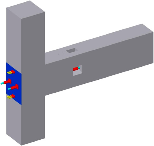
FIGURE 1. Connection detail of post-tensioned precast specimen.
A testing program has been designed to evaluate the earthquake performance of the proposed moment resisting precast concrete beam-to-column connection detail under reversed cyclic loading in order to investigate its seismic performance in terms of moment capacity, stiffness, energy dissipation and residual displacements. The test specimens have been designed as exterior joints of a multistory building assuming that the point of contraflexure in the columns and beams take place at the mid-height and mid-span under the earthquake loads, resulting an isostatic test specimen.
In this study five specimens; one monolithic and four precast, have been tested. The variables of the test specimens are summarized in Table 1. The contribution of mild steel reinforcement to the flexural moment capacity have been 22 and 40%, respectively, for the precast specimens HBD_10_0 and HBD_16_0. No initial post tensioning force has been applied to post tensioning bolts in those specimens. Although HBD_16_20 specimen has been same as HBD_16_0 for the contribution of mild steel reinforcement ratio, the initial post tensioning force has been applied on post tensioning bolts at an approximate level of 20% of the post tensioning bolt yield strength. Differentiating from the HBD_16_20 specimen, steel corbel has been placed above and below the beam to prevent beam sliding on column surface in HBD_16_20_C specimen.
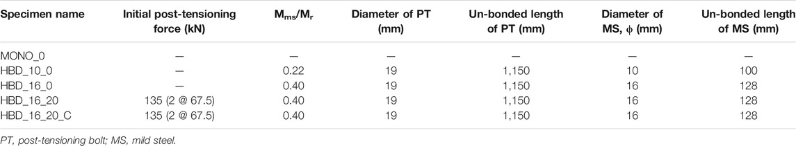
TABLE 1. Test specimens.
Test specimen geometry is selected approximately as half of the prototype structure, considering the capacity and space limitations of the laboratory and loading criteria stated in ACI T1.1-01 (ACI T1.1-01, 2001). The designed precast connection detail is shown in Figure 1. Beam dimension was 300 × 500 mm with an 1850 mm unbonded length for the post-tensioning bolts, while the 2030 mm high column’s dimension was 400 × 400 mm. Concrete cover in precast columns and beams was 20 mm.
Column longitudinal reinforcement ratio was 2.40% for the monolithic specimen. Three 10 mm diameter reinforcing bars were placed as the longitudinal reinforcement for both sides of the beam. Reinforcement configuration of the monolithic specimen is given in Figure 2. Column flexural moment capacity is designed higher than the beam flexural moment capacity in order to initiate the plastic hinging in the beam and thus strong column-weak beam design philosophy is ensured for the monolithic specimen.
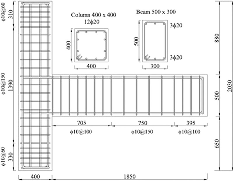
FIGURE 2. Reinforcement detail of monolithic test specimen (dimensions in mm).
The design of precast specimens was based on both the ACI-T1.2-03 guidelines and on the recommendations along with the conclusions from previously published research (ACI-T1.2-03, 2003). The flexural moment capacity of the precast connection was aimed to be close to that of the monolithic connection, provided that the beam and column capacities to be higher than the connection ultimate moment capacity. The columns and the beams of the specimens were manufactured the same in all precast connections. The main test variables in the connection are the mild steel reinforcement ratio and the initial post tensioning force applied on high-strength post tensioning bolts.
Precast column longitudinal reinforcement ratio was 2.40% similar to the monolithic specimen. The cross-section dimension of the prefabricated beam on the connection region is the same as the monolithic connection. Six 20 mm diameter mild steel reinforcing bars were placed at the top and bottom of the precast concrete beams as main flexural reinforcement. In order to mount the mild steel reinforcement and post-tensioning bolts easily, steel box sections were placed along the same axis inside the prefabricated columns and beams shown in Figure 3. The steel box, in which the mild steel reinforcement is placed, had a cross section of 80 × 40 mm; while 40 × 40 mm steel box was used on both side faces of the beam in order to place the post-tensioning bolts. The box sections of the beam were fixed to a 20 mm-thick steel plate before casting concrete. This steel plate was used also as a cushion to delay the crushing of beam concrete along the column surface throughout the loading. A similar plate with a thickness of 10 mm was placed on the column free surface to reduce the effect of point load induced by the post tensioning bolts. Steel ribs were welded around the steel boxes for better bonding between the box and the surrounding concrete, while cross-bolts were used to ensure the integrity of concrete infill and the 40 × 80 mm steel boxes used for the mild steel.
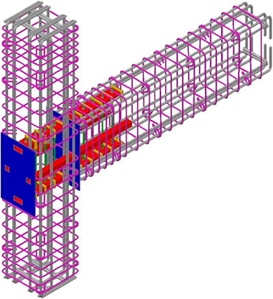
FIGURE 3. Reinforcement and connection detail of precast test specimens.
In the assembly phase of the precast elements, the beam was seated on a scaffolding leaving a 20 mm gap to the column, later was filled with a non-shrink steel fiber reinforced concrete with an ultimate compressive strength of 90 MPa. After 24 h, mild steel reinforcements were placed inside the 40 × 80 mm steel boxes and fastened without pre-stressing. The steel box with the mild reinforcement was filled with high strength mortar for full bond. On the other hand, a short unbounded length was created on the mild steel through the application of a smooth surface plastic cover on the rebar, and was centered to the beam-column interface given in Table 1. The aim of the un-bonded length was to avoid the reinforcement rupture at small drift levels. Finally, post tensioning bolts were placed inside the 40 × 40 mm. No mortar was used for the post-tensioning bolts.
The compressive strength of concrete was 42 MPa. The diameter of reinforcing steel for the flexural and shearing reinforcement in the monolithic and precast members were 20 and 10 mm, respectively. In addition, 10 and 16 mm diameter reinforcement were used as mild steel reinforcement for post tensioning precast connection specimens. For all test specimens, the yield and ultimate strength of the flexural reinforcement were 530 and 630 MPa, while these values for the shear reinforcement were 470 and 700 MPa, respectively. However, yield and ultimate strength of the 16 mm reinforcing bar were 540 and 637 MPa, respectively. The reinforcing steel elongation at ultimate strength was 16% for the 10 and 20 mm diameter bar, and 13% for the 16 mm diameter bar. The high strength post tensioning bolt has a tensile strength of 1,400 MPa, and a yield strength of 1,200 MPa. Elongation at ultimate strength is 15% for steel bolts. The post tensioning bolts were specially manufactured in length and property suitable for the connection geometry. Material strengths were determined by tests carried out in the accredited testing laboratory.
Quasi-static, reversed cyclic loading was applied to the specimens. In the first step of the loading, an axial load of 10% of the column capacity was applied to the column and this axial force was kept constant through the lateral loading scheme. Test setup and the measurement system shown in Figure 4 were designed accordingly in order to use the criteria described in ACI-T1.1-01. The lateral load was applied to the top of the column, while the bottom of the specimen was free to rotate and the beam end was designed as roller support. The lateral load protocol was applied to the top end of the column by a displacement controlled hydraulic actuator, according to the loading history proposed in ACI T1.01. Three full cycles were realized at each displacement level. The first cycle was in the linear region (0.15 and 0.20% story drift) and loading steps were gradually increased.
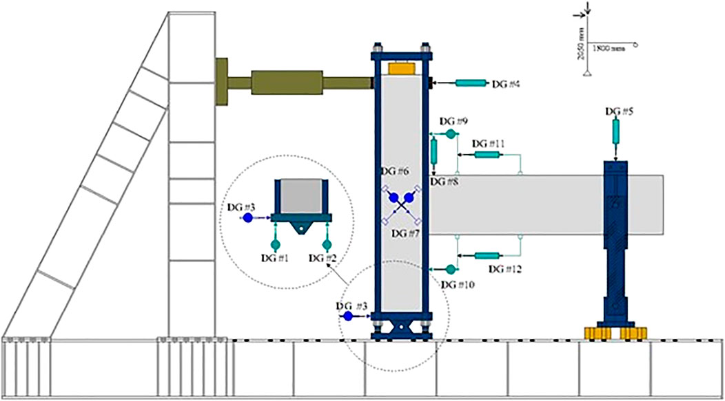
FIGURE 4. Test setup and instrumentation.
Linear variable displacement transducers (LVDTs) are mounted on the test specimens to measure the story displacement of the column, sliding deformation that may occur at the bottom joint and beam end, curvature at the beam end, sliding of the beam end relative to the precast column surface and the openings on the column-to-beam interface. All experimental data have been collected and stored electronically and cracking, yielding, failure loads and displacements of specimens were monitored and crack patterns were recorded simultaneously. The drift level is computed as the ratio of story displacement to column height. The net displacement at the column top is called the story displacement and calculated according to Eq. 1.
In this equation, the net column displacement (Δnet) is obtained by subtracting the column base lateral displacement (Δcb) and the vertical beam end displacement (Δbv) from the measured lateral displacement on the column top (Δct). Actually, the rigid body movement was deducted from the top displacement of the column, in order to obtain the net displacement causing internal forces. Load cells were installed at the external surface of column in order to measure the initial effective post-tensioning force in the post-tensioning bolts and to measure the changes in the post-tensioning force during the experiment. Strain gauges were placed on the steel bars to determine the yield displacement of the mild steel reinforcements.
Experimental results and the observed connection behavior during the experiment are presented in this section. The damage mode of failure for the specimens are presented in Figure 5.
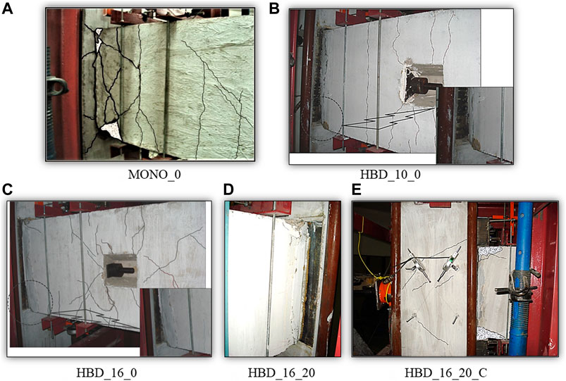
FIGURE 5. Damage in test specimens at the 4% story drift ratio. (A) MONO_0. (B) HBD_10_0. (C) HBD_16_0. (D) HBD_16_20. (E) HBD_16_20_C.
The monolithic specimen performed nearly elastic in the first two cycles of the 0.25% drift level. At the 0.75% story drift level, flexural cracks observed on the column close to the connection region. Diagonal microcracks on beam appeared at 1.00% story drift level. Yielding of beam flexural reinforcement was observed at 1.40% story drift cycle. Concrete spalling on lower compression block of the beam took place 2.20% story driftratio. At the second cycle of the drift ratio 4.0%, bottom reinforcement was buckled as shown in Figure 5A. Lateral load-story drift response of the specimen is shown in Figure 6. The measured ultimate lateral load for the push and pull cycles is 120 and −117 kN, respectively. No significant strength degradation has been observed in the monolithic connection until 4.00% story drift level, and the behavior was ductile.
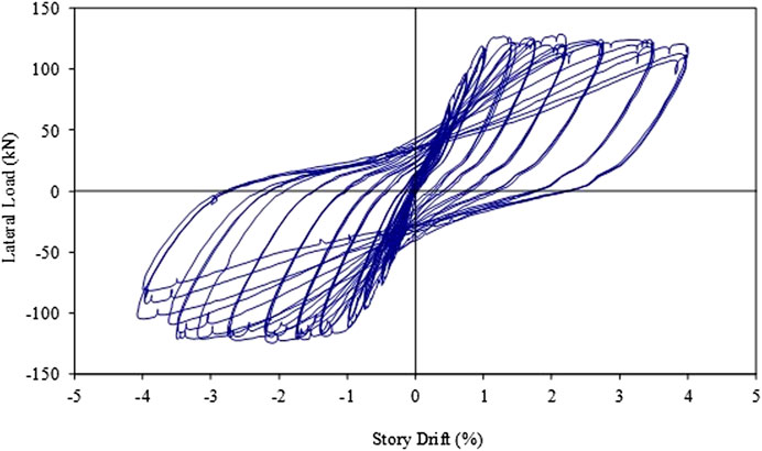
FIGURE 6. Load—story drift response of specimen MONO_0.
The damage in precast connections is usually gathered at the connection region due to opening and closing of the crack that occurs on the connection interface. As the moment capacity of prefabricated members has been designed higher than the moment capacity of the connection, no significant damage has been observed in prefabricated members during the tests.
No initial post-tensioning was applied to the post-tensioning bolts. The first hairline crack took place at 0.20% story drift level on the connection interface, while the mild steel reinforcement of the connection yielded during the 0.75% drift cycle. Residual displacements in the form of vertical sliding at the interface became visible at 1.40% drift ratio. Due to the early yielding, the bottom mild steel reinforcement in the connection was buckled in the first cycle at 2.75% story drift level. At 4.00% story drift level, the concrete on the compression face was crushed at the connection region as shown in Figure 5B. The lateral load versus-story drift behavior is presented in Figure 7. Maximum lateral load was measured as 84 kN during compression and -71 kN during tension. Maximum tension in the post tensioning bolts was measured as 790 MPa (Force is 224 kN). The gap opening at the beam-column interface reached a maximum level of 30.0 mm at the 4.00% drift cycle, and the vertical sliding of the beam on column surface was 15.5 mm.
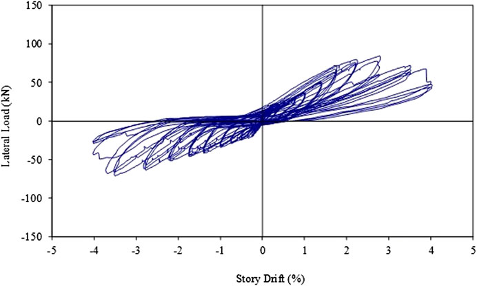
FIGURE 7. Load—story drift response of specimen HBD_10_0.
No initial post-tensioning was applied to the post-tensioning bolts. Yielding of the top mild steel reinforcement at the interface took place at the first cycle of 0.75% drift level. The gap opening at the interface reached to 6 mm at 1.40% story drift level. In the first cycle of the 4% story drift ratio, the mild steel reinforcement at the bottom of the connection. Residual displacement in the specimen was about 51.8 mm at the end of the test and Figure 5C illustrated the last damage mode of the precast specimen. Lateral load-story drift graph is presented in Figure 8. Maximum lateral load was 114 kN at push and −104 kN at pull cycles. The maximum measured tensile stress in the post tensioning bolts was 889 MPa (Force is 252 kN). The gap opening at the column-beam connection interface reached a maximum level of 26.8 mm at the 4.00% story drift level. The amount of vertical sliding of the beam on the column surface was measured as 13.1 mm.
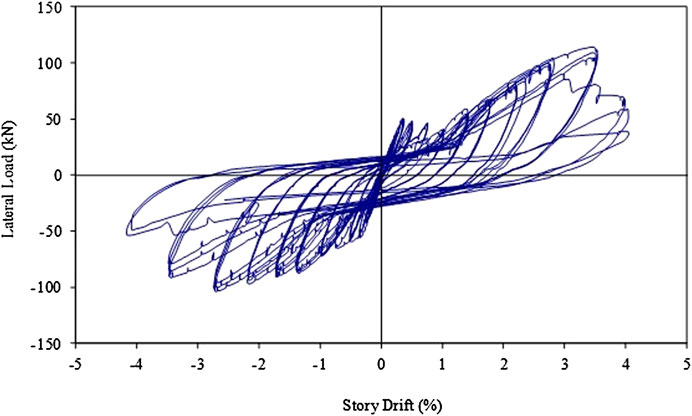
FIGURE 8. Load—story drift response of specimen HBD_16_0.
Since sudden increase in the force transferred to the post tensioning bolts took place right after the yielding of mild steel, significant relative deformations observed at the beam-column interface resulting stiffness degradations and residual sliding deformations in the previous precast specimens. For this reason, an initial post tensioning force at a level equal to the 20% of the bolt yield capacity (240 MPa) was applied in order to increase the clamping force at the interface. Similar to the previous specimens, the mild steel reinforcement yielded at 0.75% storey drift ratio. Post-tensioning force applied on bolts was effective on the overall behavior. Mild steel reinforcement at the bottom of the interface ruptured at the second push cycle of 4.00% drift ratio as shown in Figure 5D. Lateral load-storey drift behavior is presented in Figure 9. Maximum measured lateral load is 130 kN during push and −126 kN pull cycles. The maximum measured tensile stress in the post tensioning bolts was 995 MPa (Force is 282 kN) at the 3.50% storey drift level. The gap opening at the beam-column interface reached 27.3 mm at 4.00% storey drift level.
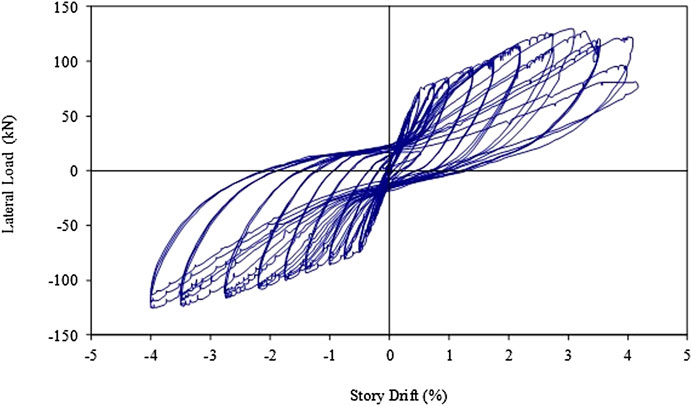
FIGURE 9. Load—story drift response of specimen HBD_16_20.
Specimen HBD_16_20_C was with small steel brackets at the top and bottom of the beam at interface in order to limit the sliding type of deformations. The first hairline cracks indicating the opening of the beam-column interface were observed at the 0.25% storey drift level, and the mild steel reinforcement yielding took place at 0.75% drift level. Hairline diagonal cracks observed in the beam at 1.40% cycle while crushing of concrete was observed on the beam-column interface at the 4.00% drift ratio as Figure 5E. No loss in the load bearing capacity was observed during the loading scheme. Lateral load-storey drift graph is given in Figure 10. Maximum measured push load was 140 kN while the pull capacity was −140 kN. Maximum tension force measured in the post tensioning bolts was 1,055 MPa (Force is 299 kN) at the 4.00% cycle. The opening at the beam-column interface reached a maximum level of 17.3 mm. Vertical relative sliding at the beam-column interface minimized with the help of steel brackets.
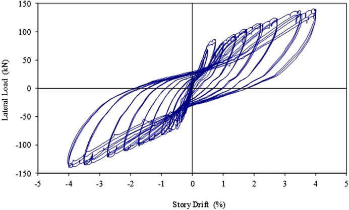
FIGURE 10. Load—story drift response of specimen HBD_16_20_C.
The comparison of the strength, failure modes, stiffness degradation, energy dissipation characteristics and residual displacement values of the monolithic and hybrid precast specimens are presented in the following section.
In most of the design codes, it is required to demonstrate that the precast connection behavior is similar or at best, equivalent to that of the monolithic connection. In this study, the strength and behavior of precast connections are compared to the monolithic specimen by using the lateral load—story drift envelope curves presented in Figure 11. In addition, the moment capacity of each connection is determined by processing the load displacement curves obtained from experiments. According to the results, while the moment capacity of the monolithic connection is 218 kN m, the HBD_10_0 connection moment capacity decrease to 133 kN m. The moment capacity of the HBD_16_0 connection reached 85% of the capacity of the monolithic connection and 95% of the HBD_16_20 connection. HBD_16_20_ C connection moment capacity is determined as 231 kN m and the moment capacities of the HBD_16_20_ C connection exceeded that of the monolithic connection by 7%. The behavior of the precast specimens with prestressing force applied to the high strength tendons are very similar to the monolithic connection. The load carrying capacity of the HBD_16_20_C continued has increased without loss until the end of the 4.00% drift cycle. In this case, when the vertical sliding of the precast connection is prevented with a corbel, it behaves similar to a monolithic connection.
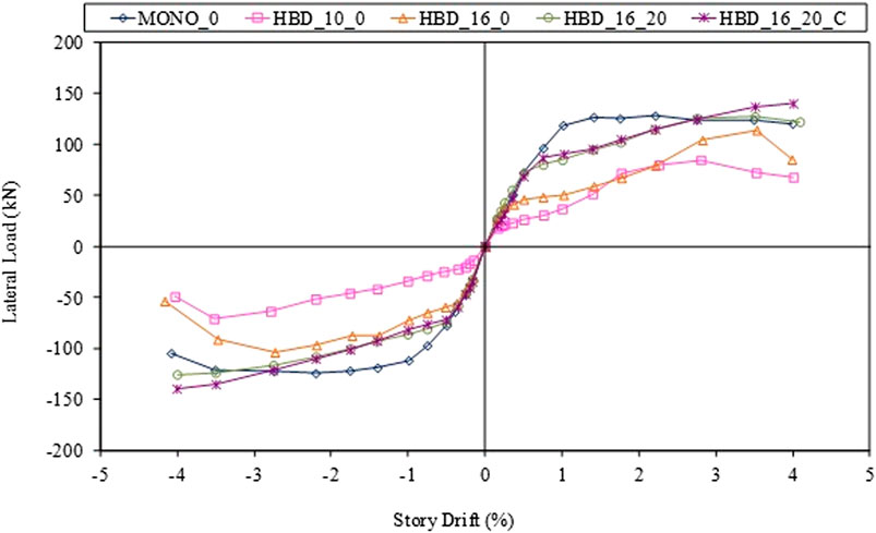
FIGURE 11. Envelop curves of specimens.
The high-strength steel post-tensioning bolts in the precast connections provided higher initial stiffness values as compared to the monolithic connection. This higher initial stiffness values may be considered beneficial in reducing the damage in non-structural (architectural) elements at low level seismic excitations.
The stiffness degradation is calculated by considering the secant stiffness (Ksec) changes in the specimens. The secant stiffness values, Ksec are calculated according to the ACI T1.1-01 approach, by taking the push and pull peak points into account in the third cycle of each story drift level (Priestly et al., 2007). Test results are normalized by dividing the measured Ksec of each drift level to that of the 0.15% story drift cycle and the stiffness degradation curves are shown accordingly as shown in Figure 12. Secant Stiffness values, Ksec in precast and cast-in-place monolithic connections are similar at the beginning of the loading history. However, a pronounced stiffness degradation took place in the specimens without post-tensioning due to the yielding of the mild steel. On the other hand, initial post-tensioning force and placing steel corbels at the bottom and the top side of the beam reduces the stiffness degradation as presented in Figure 12.

FIGURE 12. Stiffness degradation of specimens.
The energy dissipation capacities of test specimens are calculated according to the method given in ACI T1.1-01. In order to emphasize the energy dissipation characteristics of the precast connections, the relative energy dissipation ratio vs. the story drift graphs are presented in Figure 13. The concept of energy dissipation is defined in ACI T11-01 as an acceptance criterion for such connections. The dissipated energy can be measured as the loop area in the third cycle of a given story drift level. Normalization of this value is evaluated according to the elasto-plastic behavior of the specimen at this specified drift cycle. As an acceptance criterion according to ACI T1.1-01, the maximum relative energy loss rate of a subassembly must be equal to 1/8 of the third cycle value at the 3.5% drift ratio.
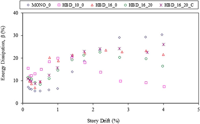
FIGURE 13. The relative energy dissipation ratios vs. story drift response.
Precast connections without steel corbel display almost the same behavior and dissipated more energy than the monolithic connection until the 1.70% storey drift ratio. Beyond this drift level, the trend changes and the energy dissipation values of precast connections decrease as compared to the monolithic specimen. The energy dissipation graphs yield that the specimen with post tensioning and with steel corbel (HBD_16_20_C) revealed the best performance, similar to the monolithic specimen.
Residual displacements are observed in many structures instead of inelastic deformations take place. This residual displacement is closely related to the maximum ductility level for the yielding beam-to-column connection. It should be noted that, although the energy dissipation of the connection is positively affected by the increasing residual displacements, it also causes an increase in the repair and strengthening costs of the buildings after the earthquake (Christopoulos and Pampanin, 2004). The maximum possible residual displacement is mainly a function of the unloading curve stiffness and the last residual displacement value (Christopoulos et al., 2003a; Christopoulos et al., 2003b).
The design philosophy of post tensioned connections is based on preventing residual damage in structural members after an earthquake. In case of residual story displacement in the structure, residual rotation will occur at beam ends according to the strong column-weak beam design philosophy. Figure 14 illustrates the residual displacement-story drift behavior for test specimens. Residual displacements, observed until the mild steel reinforcement yielding load level in precast connections, are at their minimum. On the other hand, the behavior of precast connection with mild steel ratio of %10 depending on the residual displacement is not consistent. At the 4% story drift level, a 20 mm residual displacement was recorded for specimen HBD_10_0. Prior to yielding of the mild steel reinforcement in specimens HBD_16_20, the residual displacements were minor. After the reinforcement yielding point, permanent displacements reached 15 mm at the end of the test. The residual deformation characteristics of monolithic specimen and the specimen with post tensioning and with steel corbel (HBD_16_20_C) are remarkably similar.
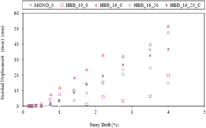
FIGURE 14. Residual displacements at the specimens depending on the story drift.
The following conclusions are from the results of the current experimental investigation.
• The damage in post tensioned precast connections is mainly observed in the beam-column interface due to the opening and closing of the first crack. The damage in all precast members is at a negligible level. However, vertical relative sliding of the beam on the column surface after the yielding of mild steel reinforcement becomes more dominant in specimens without post-tensioning. The sliding at the interface leads to mild steel reinforcement rupture less than the expected story drift levels.
• The post tensioned precast connection with steel corbel system as in the HBD_16_20_C specimen prevents the rupture of mild steel reinforcement and maintains the connections load bearing capacity even at higher story drift levels, even during the 4.00% story drift ratio. Also, this specimen may well be an alternative to the monolithic connection with reduced onsite construction time.
• In precast connections the stiffness was similar to the monolithic specimen at the beginning of the drift ratios. However, a pronounced degradation is started due to the opening and closing of the crack at the beam-column interface. Application of initial post-tensioning instead of the high strength bolts and placing a corbel to reduce the relative sliding of beam, as with the HBD_16_20_C connection, not only increases the initial stiffness but also reduces stiffness degradation.
• The HBD_16_20_C, one of the precast connections, displayed the closest energy dissipation behavior similar to the monolithic connection.
• The results of this experimental study show that the performance of the HBD_16_20_C precast connection was satisfactory based on the seismic performance evaluation recommended by ACI T1.1R-0. This indicates that the precast structure utilizing the beam-column connection has a proper lateral force resistance against seismic loads.
All datasets presented in this study are included in the article.
HA designed the connection specimens, conducted the experiments, analyzed the results, and wrote the manuscript. SO supervised the studies and support her. Both authors contributed to the article and approved the submitted version.
Part of the present study was supported by the Republic of Turkey Kocaeli Governorship.
The authors declare that the research was conducted in the absence of any commercial or financial relationships that could be construed as a potential conflict of interest.
The authors extend their appreciation to Kocaeli University Structures Laboratory staff for their invaluable contributions in the preparation and testing of the specimens.
ACI Innovation Task Group 1 (2003). ACI T1. 2‐03‐Special hybrid moment frames composed of discretely jointed precast and post-tensioned concrete members. American Concrete Institute, Farmington Hills, MI.
Adalier, K., and Aydingun, O. (2001). Structural engineering aspects of the june, 1998 adana–ceyhan (Turkey) earthquake. Eng. Struct. 23, 343–355. doi:10.1016/s0141-0296(00)00046-8
Amaris, A., Pampanin, S., and Palermo, A. (2006). “Uni and bi-directional quasi static tests on alternative hybrid precast beam column joint subassemblies,” The New Zealand society for earthquake engineering conference, New Zealand, June 2006.
Bhatt, P., and Kirk, D. W. (1985). Test on an improved beam column connection for precast concrete. ACI Struct. J. 82, 834–843.
Bruneau, M. (2002). Building damage from the marmara, Turkey earthquake of august, 1999. J. Seismol. 6, 257–377. doi:10.1023/a:1020035425531
Cheok, G. S., and Lew, H. S. (1993). Model precast concrete beam to column connections subject to cyclic loading. PCI J. 38, 80–92. doi:10.15554/pcij.07011993.80.92
Cheok, G., Stone, W., Stanton, J., and Seagen, D. (1994). Beam-to column connection for precast concrete moment-resisting frames, Proc.4th joint technical coordinating committee on precast seismic structural systems. Tsukuba, Japan, May 1994.
Christopoulos, C., Pampanin, S., and Priestley, M. J. N. (2003a). Performanced-based design seismic response of frame structures including residual deformations. part-I: single-degree of freedom systems. J. Earthq. Eng. 7, 97–118. doi:10.1080/13632460309350443
Christopoulos, C., Pampanin, S., and Priestley, M. J. N. (2003b). Performanced-based design seismic response of frame structures including residual deformations. part-II: multi-degree of freedom systems. J. Earthq. Eng. 7, 119–147. doi:10.1080/13632460309350443
Christopoulos, C., and Pampanin, S. (2004). Towards performance-based seismic design of MDOF structures with explicit consideration of residual deformations. ISET J. Earthq. Technol. 41, 53–73.
Crisafulli, F. J., and Restrepo, J. I. (2003). Ductile steel connections for seismic resistant precast buildings. J. Earthq. Eng. 7, 541–553. doi:10.1080/13632460309350463
Dolan, C. W., and Pessiki, S. P. (1989). Model testing of precast concrete connections. PCI J. 34, 84–103. doi:10.15554/pcij.03011989.84.103
Dolan, C. W., Stanton, J. F., and Anderson, R. G. (1987). Moment resistant connection and simple connection. PCI J. 32, 62–74. doi:10.15554/pcij.03011987.62.74
Englekirk, R. E. (1990). Seismic design consideration for precast concrete multistory buildings. PCI J. 35, 40–51. doi:10.15554/pcij.05011990.40.51
Ersoy, U., and Tankut, T. (1993). Precast concrete members with welded plate connections under reversed cyclic loading. PCI J. 38, 94–100. doi:10.15554/pcij.07011993.94.100
Ertas, O., Ozden, S., and Ozturan, T. (2006). Ductile connections in precast concrete moment resisting frames. PCI J. 51, 2–12. doi:10.15554/pcij.05012006.66.76
French, C. W., Amu, O., and Tarzikhan, C. (1989a). Connection between precast elements-failure outside connection region. J. Struct. Eng. 115, 316–340. doi:10.1061/(asce)0733-9445(1989)115:2(316)
French, C. W., Amu, O., and Tarzikhan, C. (1989b). Connection between precast elements-failure within connection region. J. Struct. Eng. 115, 3171–3192. doi:10.1061/(asce)0733-9445(1989)115:12(3171)
Ghosh, S. K. (1995). Observations on the performance of structures in the kobe earthquake of january 17, 1995. Pcij 40, 14–22. doi:10.15554/pcij.03011995.14.22
Hawkins, H. M., and Iverson, J. K. (1994). Performance of precast prestressed building structure during Northridge earthquake. PCI J. 39, 38–55.
Hawkins, N. M., and Ghosh, S. K. (2004). Requirements for the use of PRESSS moment-resisting frame systems. PCI J. 49, 98–103. doi:10.15554/pcij.03012004.98.103
Korkmaz, H. H., and Tankut, T. (2005). Performance of a precast concrete beam-to-beam connection subject to reversed cyclic loading. Eng. Struct. 27, 1392–1407. doi:10.1016/j.engstruct.2005.04.004
Mitchell, D., DeVall, R. H., Saatçioğlu, M., Simpson, R., Tinavi, R., and Tremblay, R. (1995). Damage to concrete structures due to the 1994 Northridge Earthquake. Can. J. Civ. Eng. 22, 361–377. doi:10.1139/l95-047
Nakaki, S. D., Englekirk, R. E., and Plaehn, J. L. (1994). Ductile connectors for a precast concrete frame. PCI J. 39, 46–59. doi:10.15554/pcij.09011994.46.59
Nakaki, S. D., Stanton, J. F., and Sritharan, S. (1999). An overview of the PRESSS five-story precast test building. PCI J. 44, 26–39. doi:10.15554/pcij.03011999.26.39
Ochs, J. E., and Ehsani, M. R. (1993). Moment resistant connections in precast concrete frames for seismic regions. PCI J. 38, 64–75. doi:10.15554/pcij.09011993.64.75
Ozden, S., Akpinar, E., Erdogan, H., and Atalay, H. M. (2014). Performance of precast concrete structures in october 2011 Van earthquake, Turkey. Mag. Concr. Res. 66, 543–552. doi:10.1680/macr.13.00097
Ozden, S., and Ertas, O. (2007). Behavior of unbonded post-tensioned precast concrete connections with different percentages of mild steel reinforcement. PCI J. 52, 32–44. doi:10.15554/pcij.03012007.32.44
Palmieri, L., Saqan, E., French, C. W., and Kreger, M. (1997). “Ductile connections for precast concrete frame system,” in Mete A. Sozen symposium—a tribute from his students SP 162-13, Farmington Hills, MI, January 1997, 313–355.
Pampanin, S. (2005). Emerging solution for high seismic performance of precast/prestressed concrete buildings. J. Advanced Conc. Tech. 3, 207–223. doi:10.3151/jact.3.207
Parastesha, H., Hajirasoulihab, I., and Ramezanic, R. (2014). A new ductile moment-resisting connection for precast concrete frames in seismic regions: an experimental investigation. Eng. Struct. 70, 144–157. doi:10.1016/j.engstruct.2014.04.001
Park, R. (1995). A perspective on the seismic design of precast concrete structures in New Zealand. PCI J. 40, 40–60. doi:10.15554/pcij.05011995.40.60
Pillai, S. U., and Kirk, D. W. (1981). Ductile beam-column connection in precast concrete. ACI Struct. J. 8, 480–487.
Priestly, M. J. N., Calvi, G. M., and Kowalsky, M., J. (2007). Displacement-based seismic design of structures. Pavia, Italy: IUSS Press.
Priestly, M. J. N., Sritharan, S., Conley, J. R., and Pampanin, S. (1999). Preliminary results and conclusions from the PRESSS five-story precast test building. PCI J. 44, 42–67.
Restrepo, J. I., Park, R., and Buchanan, A. H. (1995). Design of connections of earthquake resisting precast reinforced concrete perimeter frames. PCI J. 40, 68–80. doi:10.15554/pcij.09011995.68.80
Seckin, M., and Fu, H. C. (1990). Beam-column connections in precast reinforced concrete construction. ACI Struct. J. 87, 252–261.
Soubra, K., S., Wight, J. K., and Naaman, A. E. (1993). Cyclic response of fibrous cast-in-place connections in precast beam-column subassemblages. ACI Struct. J. 90, 316–323.
Stanton, J. F., Hawkins, N. M., and Hicks, T. R. (1991). PRESSS Project 1.3: connections classifications and evaluations. PCI J. 36, 62–71. doi:10.15554/pcij.09011991.62.71
Stanton, J., Stone, W. C., and Cheok, G. S. (1997). A Hybrid reinforced precast frame for seismic regions. PCI J. 42, 20–23. doi:10.15554/pcij.03011997.20.23
Stone, W. C., Cheok, G. S., and Stanton, J. F. (1995). Performance of hybrid moment resisting precast beam–column concrete connections subjected to cyclic loading. ACI Struct. J. 91, 229–249. doi:10.14359/1145
Toniolo, G., and Colombo, A. (2012). Precast concrete structures: the lessons learned from the L’Aquila earthquake. Struct Concr, 13 pp. 78–83. doi:10.1002/suco.201100052
Keywords: precast structures, moment-resisting connection, post-tensioning bolt, spring steel, strength, ductility
Citation: Meydanli Atalay H and Ozden S (2021) Cyclic Behavior of Beam-Column Connections in Precast Structures. Front. Built Environ. 7:639778. doi: 10.3389/fbuil.2021.639778
Received: 09 December 2020; Accepted: 07 January 2021;
Published: 11 February 2021.
Edited by:
Andrea Belleri, University of Bergamo, ItalyReviewed by:
Vasile-Mircea Venghiac, Gheorghe Asachi Technical University of Iaşi, RomaniaCopyright © 2021 Meydanli Atalay and Ozden. This is an open-access article distributed under the terms of the Creative Commons Attribution License (CC BY). The use, distribution or reproduction in other forums is permitted, provided the original author(s) and the copyright owner(s) are credited and that the original publication in this journal is cited, in accordance with accepted academic practice. No use, distribution or reproduction is permitted which does not comply with these terms.
*Correspondence: Hilal Meydanli Atalay, aGlsYWwubWV5ZGFubGlAa29jYWVsaS5lZHUudHI=
Disclaimer: All claims expressed in this article are solely those of the authors and do not necessarily represent those of their affiliated organizations, or those of the publisher, the editors and the reviewers. Any product that may be evaluated in this article or claim that may be made by its manufacturer is not guaranteed or endorsed by the publisher.
Research integrity at Frontiers
Learn more about the work of our research integrity team to safeguard the quality of each article we publish.