
94% of researchers rate our articles as excellent or good
Learn more about the work of our research integrity team to safeguard the quality of each article we publish.
Find out more
ORIGINAL RESEARCH article
Front. Built Environ., 20 December 2021
Sec. Earthquake Engineering
Volume 7 - 2021 | https://doi.org/10.3389/fbuil.2021.639777
This article is part of the Research TopicAdvances in Seismic Performance and Risk Estimation of Precast Concrete BuildingsView all 11 articles
 Lorenzo De Stefani*
 Roberto Scotta
Recent earthquakes in southern Europe highlighted that the connections of cladding panels to R.C. frames in precast buildings had a major role in the structural collapse. For this reason, there is an urgent need for a review of the design methods for these connections as well as for an improvement in the manufacturing technology. This article aimed to assess the efficiency of dissipative panel-to-structure and roof connections in R.C. precast buildings. A parametric study consisting of linear and non-linear analyses on one case-study building is performed. Different sensitivity analyses are performed varying their mechanical properties (i.e., stiffness, strength, and ductility) to analyze the behavior of the CP/frame connections. The study focuses on dissipative connections with an elastic–plastic behavior, placed between cladding panels (CPs) and frames in precast buildings with stacked horizontal cladding panels. The introduction of dissipative CP/frame connections implies the inclusion of panels in the global seismic resisting system. The “panels + frame” system highlights a high stiffness until the yield strength of the CP/frame connections is reached. The results, obtained from non-linear dynamic analyses (NLDAs), clearly show how the proposed connection improves the structural seismic performance. By contrast, this is no longer true for R.C. precast structures with flexible diaphragms, especially for intermediate columns, far from panels aligned to seismic action. In this case, significant and unexpected axial forces arise on out-of-plane connections between panels and columns. The integration of an efficient diaphragm is essential to prevent these critical issues both on intermediate columns and CP/column connections; it enables the dissipative capacity of the “panels + frame” system, and it significantly limits the forces and displacements of intermediate alignments. Unfortunately, the achievement of a rigid diaphragm is not always feasible in precast buildings. A possible alternative to activate dissipative capacities of the roof diaphragm with limited in-plane stiffness is the use of dissipative connections linking roof beams and main beams. The solutions described in this article can be applied both in the design of new buildings and for the seismic upgrading of existing ones with easy-to-install and low-impact applications.
The current design of R.C. precast buildings is typically based on bare frame models where perimetral cladding panels are considered only as seismic mass which does not contribute to the global lateral stiffness and resistance (i.e., non-structural elements (NSEs)). Cladding connections are mainly conceived to allow dimensional tolerance during the installation phase and to avoid out-of-plane overturning of the panels. Therefore, the panels are typically linked to the structure with fragile connections designed with local calculations for wind and/or seismic actions, thus evaluating only anchoring forces orthogonal to the plane of the panels.
Recent earthquakes in Italy, in particular L’Aquila 2009 (Menegotto 2009; Colombo and Toniolo 2012a) and Emilia 2012 (Colombo and Toniolo 2012b), have tragically demonstrated the shortcomings of this design approach.
Independent of the theoretical design approach of their connections, cladding panels behave as shear walls modifying the seismic response of precast buildings. The higher stiffness of the resisting system leads to higher global seismic forces than those evaluated with a frame model. Moreover, forces on panel connections are related to the global mass of the building, and they mainly lay in the plane of the panels. Therefore, forces on the connections are completely different from those evaluated with a local design approach.
Furthermore, the seismic force reduction in precast structures can be related on energy dissipation due to the development of plastic hinges at the base of the columns. Very large displacements at the top of the columns are required to activate this energy dissipation, and usually, the displacement capacity of the connections ends before the complete development of the required drift. Therefore, the design of these connections cannot be related with the seismic behavior factor used for the design of the bare structure.
Based on the previous considerations, the need for new technological solutions for connections designed with a consistent conceptual approach is undeniable.
Arnold (1989) proposed the following classification for cladding panels:
-completely separated cladding: not interfering with the lateral stiffness and resistance;
- accidentally participating cladding: characterized by a gap with the structural system too small compared to the seismic demand;
- controlled participating cladding: claddings contribute to the stiffness and damping of the structure (Pinelli et al., 1995, 1996; Craig et al., 1992; National Institute of Standards and Technology, 1998; Shultz et al., 1994; Ferrara et al., 2011);
- fully participating cladding: claddings are fully integrated in the lateral force resisting system (Biondini et al., 2013a; Magliulo et al., 2014).
Moreover, Colombo and Toniolo (2012b) presented some solutions to avoid panel collapse due to connection failure:
- the use of a statically determined support system, making the panels independent from the motion of the structure and allowing their rigid motion;
- the use of an integrated support system, well-proportioned, which makes the panels an effective part of the resisting structure.
The first approach was followed by Dal Lago et al. (2012) who carried out an experimental study of sliding bidirectional connections for efficient statically determined support systems.
Applying the second approach, Biondini et al. (2013a) presented an integrated frame-wall system with dissipative connections for precast building with the vertical panel.
Scotta et al. (2015) proposed an integrated frame-wall system with dissipative connections for precast buildings with horizontal panels. They also highlighted the development of very high axial forces on the out-plane CP/column connections in precast buildings with deformable roof, defining this behavior as the “skew effect.”
Belleri et al. (2016) investigated the in-plane performance of the horizontal precast RC panel in one-story precast building.
Biondini et al. (2013b) highlighted the importance of a rigid roof diaphragm for enhancing the effectiveness of the integrated frame/wall support system with dissipative connections.
In this article, a fully stacked arrangement of horizontal CPs is considered. The CPs are placed one on the top of each other, and their weight loads the foundation beam.
Different from the previous work by the same authors (Scotta et al., 2015), a modified constraint pattern of panels is assumed:
- CP/frame connections sliding in the plane of the panels,
- CP/frame connections pinned in the out-of-plane of the panels,
- panel-to-panel fixed connections.
Dissipative connections are introduced between the main beam and the top panel, where the higher relative displacement between panels and frame develops.
Figure 1 represents constraints and in-plane independent movement of the dual structure.

FIGURE 1. In-plane and out-of-plane constraints and DOF.
This work demonstrates that the use of this type of CP/frame connections drastically modifies the seismic response of precast buildings, reducing global displacements and generalized stresses on columns compared to the bare frame structure. Moreover, for buildings with flexible diaphragms, the study shows a limited effectiveness in reducing forces on columns of intermediate alignments.
As suggested by Biondini et al. (2013b), a rigid roof floor could be realized to prevent this critical behavior. However, in precast buildings, a rigid diaphragm is not always feasible due to long spans and repetitive large openings at the roof level and for the interferences of suspended plants in existing buildings to be retrofitted.
Therefore, the effectiveness of a possible alternative solution to the rigid roof diaphragm is evaluated: the introduction of ductile elastic-plastic translational connections between roof beams and the main beams (Supplementary Figure S1) able to activate a dissipative capacity in the roof diaphragm with limited in-plane stiffness.
The case study analyzed is the same presented in Scotta et al., 2015, but with horizontal cladding panels (Supplementary Figure S2) and a different restrain system for them (Figure 1).
A typical single-story precast RC building with CPs in horizontal configuration is analyzed (Figure 1). Its plan dimensions are 20.0 × 26.0 m. The structure is composed by
- 10 columns with a square cross-section 60 × 60 cm and 9.0 m high. Four columns (P1) are located at the corners of the building. Two columns (P2) are in the middle of short sides of the building. Four columns (P3) are placed in the middle of long sides of the building, to support panels and to allow openings;
- 4 main beams with I-section (W x H = 60 × 100 cm) along the X direction, simply supported by columns P1 and P2, with a span of 10 m;
- 8 roof beams, with TT 100/250 cm shaped sectiocons, supported by main beams, with free spans of 26 m along the Y direction. They are assumed pinned to main beams, creating a deformable roof diaphragm;
- 6 secondary beams (beam-holder panels) with rectangular cross-section (W x H = 0.4 × 0.6 m) supported by columns P3 and P1 on both long sides of the building.
No connections exist between secondary and roof beams. Moreover, no connections are placed between P3 columns and roof beams: P3 columns are simple cantilevers used as horizontal supports of the CPs placed on the long side of the building.
Only self-weight and dead roof loads are considered in the seismic analyses:
- roof beams, TT 100/250 cm (including roof finishing) = 7.8 kN/m2,
- main beams (average weight) = 9 kN/m,
- secondary beams (beam-holder panel) = 6.0 kN/m,
- cladding panels = 3.25 kN/m2.
Figures 2, Supplementary Figure S2 and Figure 3, respectively, show floor plan, side views, and vertical sections of the building. In Figure 2, columns are identified with their labels.
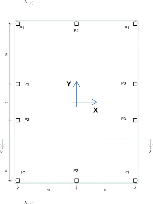
FIGURE 2. Plan view of the case-study building.
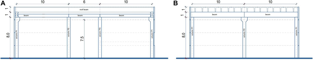
FIGURE 3. Vertical sections: (A) AA, (B) BB.
The structural FE models to simulate the different configurations have been created using Midas Gen software (Gen, 2015). The external restraints and the internal constraints are shown in the kinematic scheme of Figure 1.
The common assumptions for all the models are listed below:
- linear elastic beam elements have been used for the vertical (columns) and horizontal (main and roof beams) frame members linked with pinned connections;
- linear elastic plate elements represent the CPs;
- panel-to-panel rotational joints have been modeled using rotational plate-edge releases. Moreover, the hypothesis of the absence of relative displacements between panels was considered due to the high in-plane panel-to-panel friction assumed;
- axial rigid trusses have been used to model CP-to-column connections.
The elastic stiffness of beam elements has been evaluated from their nominal dimensions and considering a concrete elastic modulus equal to Ec = 33 GPa. The contribution of rebars and the cracking effect have been ignored.
Both modal identification and spectral analyses have been performed using an elastic model, assuming pinned connections at the roof level (i.e., the hypotheses normally assumed in design practice), without considering the structural contribution of the CPs (i.e., considering them as NSE). For spectral analyses, used as a reference for the non-linear analyses, the following parameters were assumed to define the elastic seismic spectrum according to Eurocode 8 (CEN-EN-1998-1, 2004):
Soil Type = B, S = 1.2, ag = 0.187 g → TB = 0.15 s, TC = 0.50 s, TD = 2.00 s, PGA = Sag = 0.225 g
A behavior factor q = 1.0 was assumed.
Three different sensitivity analyses (non-linear dynamic analyses (NLDAs)) were performed to assess the effects of ductile connections placed in the structure.
The first two sensitivity analyses have been used to evaluate the effects of the mechanical parameters of the CP/frame dissipative connections in precast building with deformable roof diaphragm.
The optimal CP/frame dissipative connections found have been used in the third and final sensitivity analysis with the aim to examine the introduction of ductile connections between roof and main beams and create a dissipative roof diaphragm.
The non-linearities of the structural elements were considered according to the different NLDAs performed:
- CP/frame connections;
- columns (plastic hinges at the base of the columns);
- roof/main beams connections;
Seven accelerograms spectrum-compatible with the elastic design spectrum used for spectral analyses were generated for NLDAs using the Simqke1 code (Gasparini and Vanmarcke, 1976).
A duration of 20s was assumed for the seismic action.
The numerical integration was performed using a Newmark scheme with constant acceleration parameters (c = 0.5 and b = 0.25, i.e., without numerical damping) and time-steps of 0.005 s. A Rayleigh-type damping was assumed with a damping ratio equal to ξ = 5%, a coefficient for proportional mass equal to α = 0.242 and a coefficient for proportional stiffness equal to β = 0.0015.
Results from NLDAs have been averaged over the seven accelerograms.
The following paragraphs summarize the mechanical properties assumed in the non-linear models.
The yielding ratio ry of CP/frame connections has been defined as:ry = Fy / Fel,max, where
- Fy is the yield strength of connections;
- Fel,max = 722 kN, is the maximum force on CP/frame connections derived from a reference elastic spectral analysis and assuming Kel = 80,000 kN/m.
- Fy = 0 implies no-interaction between CPs and frame (lack of CP/frame connections) which is typical for statically determined structures and usually adopted in the design. Results refer to spectral analysis and are labeled as “analytical results.”
Values of CP/frame connections parameters are listed in Table 1 for the whole investigated range of ry. The non-linear laws of connections are assumed to be bilinear elastic-plastics with hardening and unloading phase parallel to the elastic branch.
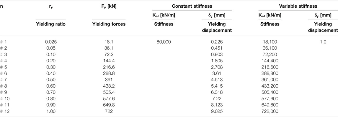
TABLE 1. Elastic-plastic laws parameters for connections.
ry has been modified to evaluate the different behavior of two limit conditions: rigid-elastic strong connections (ry = 1) and high ductility connections (ry <<).
The following properties were chosen for NLDAs:
- deformable roof (pinned connections between roof beams and main beams);
- linear elastic column;
-elastic–plastic CP/frame connections with hardening behavior (plastic stiffness Kpl equal to 1% of the elastic stiffness Kel: Kpl = Kel/100);
The sensitivity analyses consider the variation of the yielding ratio of CP/frame connections, 0.0 ≤ ry≤1.0, and two alternatives for their elastic stiffness:
- constant stiffness Kel = 80,000 kN/m with variable yielding displacement δy (see Supplementary Figure S3A)
- variable stiffness Kel with constant yielding displacement δy = 1.0 mm (see Supplementary Figure S3B).
The following properties were selected for NLDAs:
- deformable roof (pinned connections between roof beams and main beams);
- non-linear column with lumped plasticity (“Takeda” type hinges placed at the base of the columns);
-elastic–plastic CP/frame connections with hardening behavior (Kpl = 0.01·Kel).
The analyses were performed with the same range of yielding ratio ry used in the first sensitivity analyses, but under the hypothesis of constant yielding displacement δy = 1 (i.e., variable elastic stiffness of the connection, according to Supplementary Figure S3B).
The following properties were chosen for NLDAs:
- non-linear column with lumped plasticity (“Takeda” type hinges placed at the base of the columns);
-elastic–plastic CP/frame connections with hardening behavior (Kpl = Kel/100) with two alternative characteristics:
ι. δy = 1.0 mm and ry = 1,00 → Kel = 722,000 kN/m
ιι. δy = 1.0 mm and ry = 0,10 → Kel = 80,000 kN/m
Concerning the roof connections, two different cases were analyzed:
- deformable roof (pinned connections between roof beams and main beams);
- roof-to-main beam connections with elastic-perfect plastic behavior (yielding force Fy = 10 kN and yielding displacement δy = 1 mm → Kel = 10,000 kN/m).
Table 2 summarizes all the variables adopted in the three sensitivity analyses.
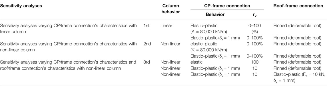
TABLE 2. Variables adopted in the sensitivity analyses.
In the following sections, the results of the simulations are summarized and discussed.
The natural frequency analysis of the elastic FE model without CP/frame connections was used to define the structural frequencies and modal shapes of the case-study building. The results are listed in Table 3 together with the corresponding mass participation. Figure 4 shows the first four modal shapes characterized by modal participation greater than 3% and involving about 80% of the total mass. Local out-of-plane modes of CPs activate the remaining mass. The modal shapes clearly reveal the absence of a rigid roof.
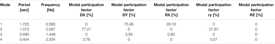
TABLE 3. Natural frequencies and modal participation.
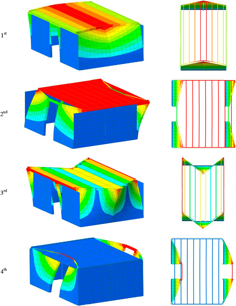
FIGURE 4. 1st to 4th modal shapes
The absence of a rigid roof causes asynchronous oscillation modes of the roof columns, and it produces opposite displacements perpendicular to the façade. This behavior induces the so-called skew effect forces on CP connections defined by Scotta et al. (2015) and subsequently analyzed by Belleri et al. (2018).
Several parametric analyses were performed to evaluate the sensitivity of the seismic response of the building to the variations of yielding forces and stiffness of CP/frame connections.
In this first sensitivity analysis, the non-linearity is concentrated on the CP-frame connections only, and the columns are considered elastic. This assumption is used to evaluate only the energy dissipation effect given by the connections.
336 NLDAs were carried out with the above-described FE models (7 earthquake signals x two earthquake directions x 12 CP/frame connection yielding forces x two CP/frame connection elastic stiffness). The average of the maximum absolute displacements and generalized stresses obtained from the seven input seismic signals are reported in Figures 5–8.
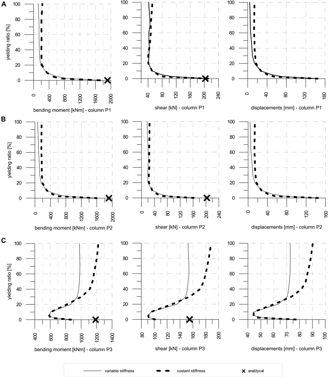
FIGURE 5. Columns - earthquake along X direction: (A) P1; (B) P2; (C) P3.

FIGURE 6. Columns – earthquake along Y direction : (A) P1; (B) P2; (C) P3.
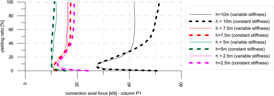
FIGURE 7. CP/column P1 connections axial force – earthquake in X direction.
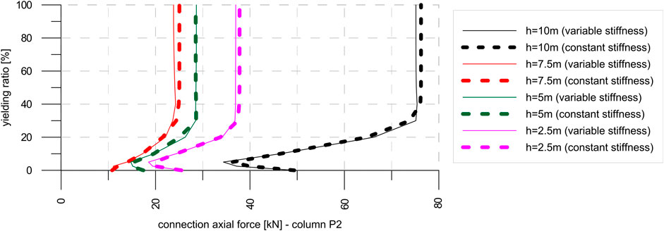
FIGURE 8. CP/column P2 connections – earthquake in Y direction: axial force.
In the following sections, the results of the analyses are commented separately for each of the structural components.
For each column type P1, P2, and P3, Figure 5 shows the envelopes of the maximum absolute values of bending moment and shear at the base and top displacements of columns when earthquake acts in the X direction.
The crosses in Figure 5 indicate the values of bending moment and shear at the base of the columns obtained by the analytical calculations; these highlight a good correspondence with numerical values derived by the models with Fy = 0.
Base forces and top displacements of P1 and P2 columns greatly reduce when yielding force of CP/frame connections increases. Moreover, it is worth noting that the numerical results highlight irrelevant variations for ratios ry higher than 20%.
A different behavior occurs at intermediate column P3. These support the out-of-plane loaded CPs and are placed far from the in-plane loaded CPs. Base forces and top displacement reduce for yielding ratios ry lower than 10% due to both the energy dissipation introduced by weak CP/frame connections and the “skew effect” which allows the migrations of the actions from out-of-plane loaded facades to the perpendicular ones, whereas base forces and top displacement increase for ry>20%, especially for constant stiffness values of the connections.
The percentage increment of the base shear is greater than those of the base bending and top displacement. This behavior underlines that an excessive in-plane stiffness of the facades parallel to the seismic action amplifies local effects on P3 column (the amplification of skew effects in not balanced by the energy dissipation).
Figure 6 shows base forces and top displacements on columns obtained for seismic action along the Y direction. Numerical results highlight a similar pattern compared to the outcomings discussed in the previous section, except for some details and the inversion of the role of P2 and P3 columns. Results are almost independent from the hypothesis of constant stiffness or constant yielding displacements for connections.
Moreover, the analytical evaluation of shear at the base of P2 column strongly underestimates the correspondent results from numerical analyses without connections (ry = 0) since the analytical model disregards the amplifications due to skew effect.
Supplementary Figure S4 shows the force values and drift of CP/frame dissipative connections, whereas Figure 7 shows axial forces on column/CP connections. Both Supplementary Figure S4 and Figure 7 display the results obtained from NLDAs with seismic action along the X direction.
Forces on CP/frame connections are linearly proportional to the yielding ratio (Supplementary Figure S4A). Since the achieved values are always greater than Fy, the yield strength of the connection is always exceeded. Stiffness variation does not affect the maximum recorded force.
By contrast, the variation of stiffness affects the displacement (drift) of the connection, especially for the highest values of ry. For ry<10%, connections with variable stiffness show greater drift than those with a constant stiffness, whereas for ry> 10%, the trend is inverted.
Figure 7 shows axial forces on column/CP connections installed on P1 column at different heights, z, equal to 2.5, 5.0, 7.5, and 10 m. Comparing the results with values obtained for ry = 0, axial forces decrease for yielding ratio ry in the 0%÷10% range; that is, the energy dissipation due to the yielding of the connection has an actual role when drift between frame and cladding panels is allowed.
In the same range, the displacement reduction and the consequent decrease in out-of-plane deformation (skew effect) are recorded together with a reduction of the axial forces on CP/column connections.
For ry>10%, the forces on the connections increase and reach higher values, especially for the connection at h = 10 m for which the plastic dissipation of the connections is no longer able to limit the skew effect.
Supplementary Figure S4 shows the forces and the drift of the CP/frame dissipative connections, and Figure 8 presents the axial forces on the column/CP connections obtained from NLDAs with seismic action along the Y direction. The graphs highlight the same trend defined for the seismic actions in the X direction.
The forces on the CP/frame connections are linearly proportional to the yielding ratio (Supplementary Figure S5A) up to ry<40%, which corresponds to the exceeding of the connection yielding strength. For ry>40%, forces on CP/frame connections become constant and related to the seismic action intensity only.
For ry>40%, the stiffness variation affects maximum force values: the connections with a constant stiffness underline a maximum force 15% higher than that in the variable stiffness case. The change in stiffness also affects the connection displacement (drift) (Supplementary Figure S5B), especially for the highest values of ry. For ry<10%, the connections with a variable stiffness show greater drifts than those with a constant stiffness, whereas for ry>10%, the trend is inverted.
Figure 8 shows the axial forces on the column/CP connections for P2 column. Comparing the results with the values obtained assuming ry = 0, the axial forces highlight a decrease for the yielding ratio ry in the 0% ÷5% range, except for connections located at the height of h = 7.5 m.
For ry> 5%, the axial forces on the connections increase, especially for connections at h = 10 m for which the damping due to the yielding of connections is not enough to limit the skew effect. The stiffness variability does not affect the maximum axial force significantly.
The effect of elastic–plastic with the hardening behavior of CP/frame connections was analyzed through 168 NLDAs with the FE model previously described (7 earthquakes x 12 connection yielding forces x two earthquake directions). Only the assumption of variable elastic stiffness was explored.
In the analyses discussed in Section 5, a linear elastic behavior of the columns was assumed. Generally, in precast buildings with cantilever columns, the energy dissipation develops at the base of the column by the formation of flexural plastic hinges. Their brittle shear collapse is avoided by placing an adequate quantity of confinement stirrups.
In this section, an improved numerical model has been adopted for the analyses: the actual hysteretic behavior of the columns (NLC) has been reproduced by introducing a lumped non-linear hinge at the base of the same.
This NLC model was used to perform the same analyses executed with the LC model for CP/frame connections with different elastic stiffness. The same geometry (B x H = 60 × 60 cm) and reinforcement bars (12Ø20 longitudinal rebars, four braces stirrups Ø10/150 mm) have been assumed for all the three column types, that is, P1–P2–P3. Since the columns are subjected to different values of the axial loads (710, 1,270, and 160 kN, respectively), three different “Takeda” hinges (Takeda et al., 1970) have been introduced in the NLC model for each column type.
Through incremental cyclic pushover analyses, the hysteretic behaviors of columns reported in Supplementary Figure S6 have been defined correlating the base bending moment and top displacement. The dashed black line in Supplementary Figure S6 identifies the elastic stiffness assumed for columns in the LC model. More details about the definition of the Takeda model parameters can be found in the study by Scotta et al. (2015).
Figure 9 shows that P1 and P2 columns highlight comparable base stresses values obtained from the LC and NLC models when ry> 20%. Therefore, for ry>20%, P1 and P2 columns remain in their linear elastic range. On the contrary, for ry<20%, the base stresses of the NLC model are limited to their capacity values.
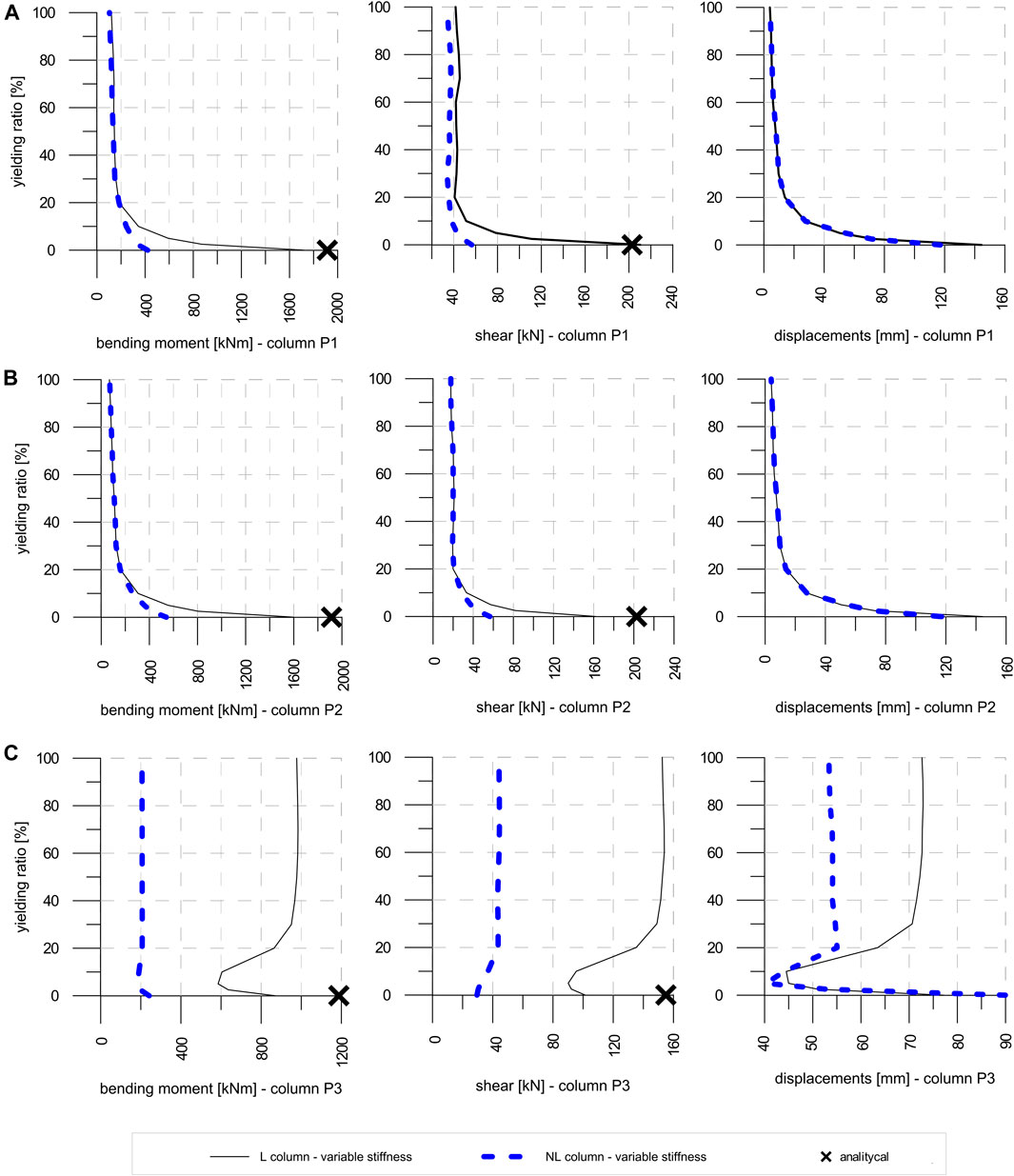
FIGURE 9. dir X: (A) P1; (B) P2; (C) P3.
Top displacements of P1 and P2 columns defined with linear and non-linear analyses correspond regardless of the ry value.
Conversely, with the LC model, P3 column (holder panel column) develops huge stresses compared to those obtained with the NLC model (blue dotted line inc Figure 9C).
For ry>20%, the use of CP/frame connections is not very effective for P3 column. The large top displacement of the column highlights the need of suitable measures to avoid pounding between the top CP and the roof elements.
Similar results have been obtained in this configuration (see Figure 10A). Different from the previous case, P2 column develops CPs when subjected to out-of-plane forces in the case of seismic action along the Y direction. P2 columns develop far higher stresses with the LC model than those obtained with the NLC model (see Figure 10B). Moreover, for ry>20%, the introduction of CP/frame connections does not induce significant forces and stresses reductions on P2 column. To avoid out-of-plane deformation of this column, amplified by the skew effect, a rigid or semi-rigid roof diaphragm would be required.
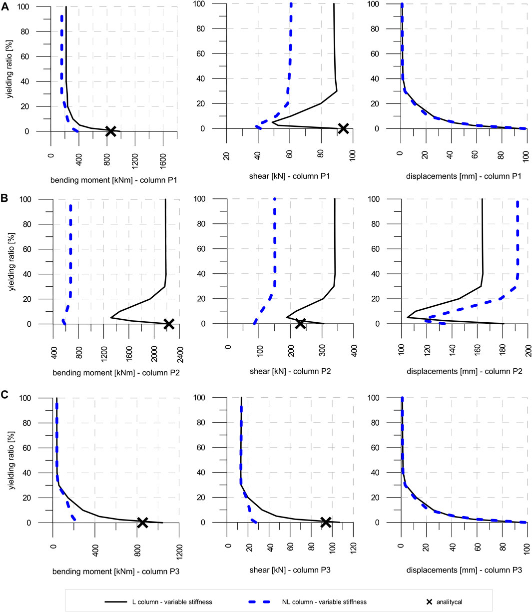
FIGURE 10. dir Y: (A) P1, (B) P2, (C) P3.
Supplementary Figure S7 shows the good correspondence of forces and drift of CP/frame dissipative connections evaluated with LC and NLC models. The comparison for the connections to column P1 in Figure 11 evidences the reduction of the axial force due to the additional dissipation provided by the yielding at the base of the columns accounted for with the NLC model. The effectiveness of the energy dissipation is particularly pronounced for the connection at h = 10 m. A reduction of the differential displacement between columns induces an attenuation of the skew effect and makes the out-of-plane forces on connections increasing with their height from the ground.
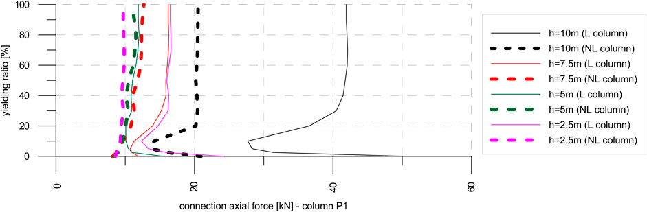
FIGURE 11. CP/column P1 - axial force on connections– earthquake along X direction.
For seismic action in the Y direction, Supplementary Figure S8 shows forces and drift on CP/frame connections, while axial forces on column/CP connections are plotted in Figure 12.
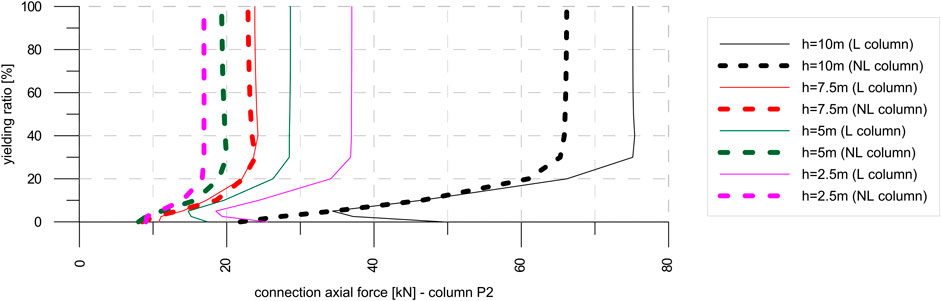
FIGURE 12. CP/column P2 connections – Y direction - axial force.
Supplementary Figure S8A highlights the following:
- when ry < 40%, the yield strength of the connection is always reached, with the forces being on CP/frame connections linearly proportional to the yielding ratio;
- when ry > 40%, forces on CP/frame connections become constant; that is, their yield strength is not exceeded. Maximum force on the connection with the LC model is about 15% greater of that obtained with the NLC model.
The use of LC or the NLC model does not significantly affect the maximum drift of the connections in columns (Supplementary Figure S8B).
With the NLC model, a mitigation of the skew effect occurs due to the dissipation at the base of the columns. The attenuation of the skew effect leads to a distribution of forces on connections proportional to their height from the ground (Figure 12).
Results discussed in Section 5 and 6 refer to precast buildings with flexible diaphragms and show limited effectiveness of the proposed CP/frame dissipative connections for intermediate columns.
The realization of a rigid diaphragm on the roof would increase the effectiveness of the connection systems (Biondini et al., 2013b), but it is not always feasible as discussed previously. Therefore, in this section, a possible alternative solution is analyzed. Elastic–plastic translational connections are introduced between roof beams and main beams to create a semi-rigid and dissipative diaphragm.
The effectiveness of this solution is evaluated through the comparison of numerical results obtained with three different models having the following properties:
First model: deformable roof (DR), ry = 100%
- elastic CP/frame connections (yielding ratio ry = 100% and elastic stiffness Kel = 722.000 kN/m);
-non-linear columns (plastic Takeda hinges with the hysteretic law in Supplementary Figure S6 are introduced at the base of the columns);
- deformable roof (pinned connections between roof beams and main beams).
2nd model: deformable roof (DR), ry = 10%
It presents the same properties of the 1st model, except for the elastic–plastic hardening CP/frame connections characterized by ry = 10% and elastic stiffness Kel = 80,000 kN/m;
Third model: flexible roof (CR), ry = 10%
Equal to the 2nd model but with semi-rigid and dissipative roof diaphragm obtained by inserting translational elastic-perfect plastic connections between roof beams and main beams as depicted in Supplementary Figure S1, characterized by yielding force Fy = 10 kN and yielding displacement δy = 1 mm (Kel = 10.000 kN/m).
Results from NLDAs with the 1st and 2nd models (DR) have already been discussed and compared within the second sensitivity analysis reported in Section 6.
The effect of the flexible roof diaphragm (CR) was investigated through 14 NLDAs on the 3rd model (7 earthquakes x one set of connections characteristics x two earthquake directions). The comparison of the numerical results obtained with the three models is illustrated in the following sections.
Figure 13 reports top displacements and bending moments at the base of P1, P2, and P3 columns for earthquakes in the X direction.
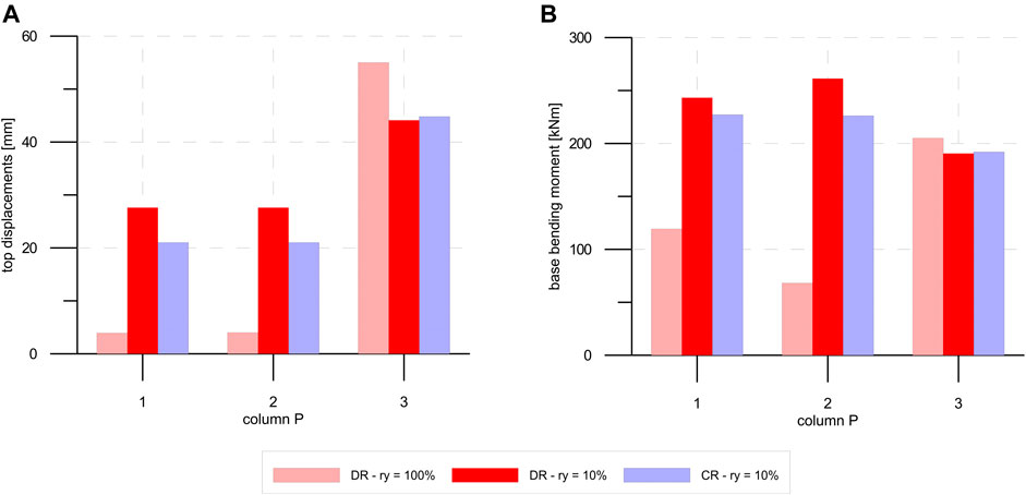
FIGURE 13. seismic action along X direction: (A) column top displacements, (B) column base bending moment.
P1 and P2 columns show a top displacement and a bending moment reduction in the CR model compared to the DR 2nd model with the same yielding ratio ry = 10%. By contrast, the creation of a semi-rigid floor does not significantly affect the results for P3 column. The worst conditions in terms of maximum top displacement and bending moment for P3 columns are represented by the case DR–ry = 100% (1st model).
Therefore, when the earthquake is applied along the X direction, the CR solution does not relieve the solicitations on P3 column, which are not connected to the roof and therefore cannot take advantage of the semi-rigid roof diaphragm.
Only the insertion of horizontal connections placed between the top of P3 columns and the roof could reduce solicitations and displacement demand of P3 column.
Figure 14 reports the same results for seismic actions along the Y direction. In this case, the CR 3rd model - ry = 10% allows a significant reduction of top displacements and base bending moments for all columns compared to the DR–ry = 10% 2nd model. Moreover, P2 column shows a reduction of the top displacement and base moment, respectively, equal to 50 and 25%, which underlines that the seismic demand on columns can be significantly reduced using dissipative connections at the roof level.
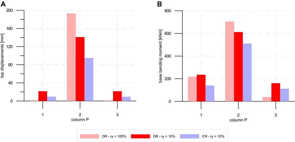
FIGURE 14. Seismic action along Y direction: (A) column top displacements, (B) column base bending moment.
Figure 15 A, B show, respectively, forces and drifts of CP/frame connections from the three models and for both earthquake directions.
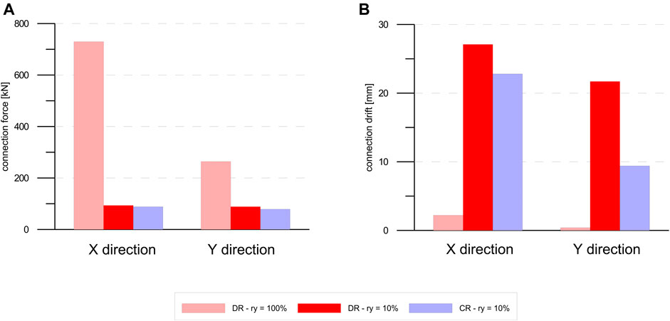
FIGURE 15. CP/frame connections: (A) force; (B) drift.
Force on connections obtained from the CR, ry = 10% 3rd model is approximately equal to that obtained with the DR, ry = 10% 2nd model since the yielding of the connection is achieved in both cases. Perhaps, connection drift is lowered with the CR, ry = 10% 3rd model: the introduction of dissipative roof connections leads to a reduction of the deformation demand of CP/frame dissipative connections.
Force on connections with the DR, ry = 100% 1st model is approximately equal to 720 kN along the X direction and to about 280 kN along the Y direction: such forces are hardly sustainable in practical installations. Therefore, the adoption of CP/frame deformable and/or elastic–plastic connections is mandatory to avoid fragile failure modes.
Supplementary Figure S9 and Supplementary Figure S10 show axial forces arising on column/CP connections located at h = 2.5, 5.0, 7.5, and 10 m from the ground level, for earthquakes acting in X and Y directions, respectively.
Results in Supplementary Figure S9 (X direction) are similar for the two ry = 10% models (DR 2nd model and CR 3rd model); that is, the introduction of roof dissipative connections does not influence the connection forces. With the DR, ry = 100% 1st model higher forces develop especially at higher CP/frame connections due to their elastic behavior, which produces an amplification of local motion on P3 column and an amplification of the skew effect.
Supplementary Figure S10 shows that for earthquakes along the Y direction, the energy dissipation produced by introducing roof dissipative connections (CR model 3rd model) reduces the axial force value on CP/column connections of about 50 and 30% compared to the DR models with ry = 100 (1st model) and ry = 10% (2nd model), respectively.
In this article, a RC precast building with fully stacked horizontal cladding panels (CPs) has been considered as a case study. The CPs are placed horizontally, one on top of each other, and their weight loads to the foundation beam. Despite the simplicity and the small number of spans of the considered building, it allowed us to explore all the typical situations in R.C. precast buildings for varying direction of seismic excitation.
Generally, the analytical approach to the design of such buildings assumes the following constraint pattern for CPs: CP/frame in-plane sliding connections, CP/frame pinned out-of-plane connections, and panel-to-panel fixed connections. These assumptions lead to consider CPs as non-structural elements (NSEs) without any resistant function. Their connections are designed to resist statically determined wind or seismic actions.
The experience from past seismic events demonstrated that CPs interact with the frame producing unpredictable dynamic behavior and inadequate seismic performances. Moreover, unexpected relevant out-of-plane forces arise in CP/frame connections in precast buildings with a deformable roof (skew effect due to out-of-plane deformation of facades).
Therefore, the possibilities of using CPs as resistant shear walls have been explored in this work.
Dissipative elastic–plastic connections have been considered to connect CPs to the frame. Sensitivity analyses have been performed exploring the variation of the generalized stresses on columns, top displacements, and forces on connections obtained, modifying the yielding force and stiffness of connections and considering both elastic and inelastic behaviors of columns. A relevant reduction of stresses and top displacements on columns with limited forces on connections have been demonstrated in an optimal configuration with dissipative connections having yielding forces in the range of 5–10% of the elastic forces that would arise in the hypothesis of elastic connections.
However, with a flexible roof diaphragm condition, the introduction of proposed CP/frame connections has limited effectiveness in reducing seismic demand on intermediate columns, away from the facades parallel to seismic action. Moreover, the use of CP/frame connections with in-plane resistance exceeding 20–30% of the elastic demand results in a worse condition for such intermediate columns, but also for columns/CP connections, due to the high amplification of the skew effect.
The realization of the in-plane rigid roof would solve such limitations and drawbacks. However, it is not easy to create rigid roof diaphragms in precast buildings due to large skylights between the roof elements or suspended plants in existing buildings.
An alternative solution consisting of a semi-rigid dissipative diaphragm’s realization has been explored with a 3rd sensitivity analysis. Such conditions can be obtained by introducing easy-to-install translational elastic–plastic dissipative connections between roof beams and main beams. It has been demonstrated that the energy dissipation assured with such roof connections allows to considerably reduce stresses and top displacements also of intermediate columns (if connected to the roof, obviously) and forces in the columns/CP connections.
This work demonstrates that a combined intervention involving the introduction of low-strength elastic–plastic dissipative connections between frame and cladding panels, columns and cladding panels, and roof beams and main beams has a significant impact on reducing the seismic demand on precast RC buildings. The solution explored in this paper can be profitable if used not only in the design of new buildings but also for the seismic retrofitting of existing ones.
The raw data supporting the conclusions of this article will be made available by the authors, without undue reservation.
LD and RS contributed to the research reported in the paper in the same way.
The authors declare that the research was conducted in the absence of any commercial or financial relationships that could be construed as a potential conflict of interest.
All claims expressed in this article are solely those of the authors and do not necessarily represent those of their affiliated organizations, or those of the publisher, the editors, and the reviewers. Any product that may be evaluated in this article, or claim that may be made by its manufacturer, is not guaranteed or endorsed by the publisher.
The authors acknowledge the contribution to the research given by Eng. Luca Grinzato with the development of his master thesis.
The Supplementary Material for this article can be found online at: https://www.frontiersin.org/articles/10.3389/fbuil.2021.639777/full#supplementary-material
SUPPLEMENTARY FIGURE 1 | Translational dissipative connections between roof beams and main beams.
SUPPLEMENTARY FIGURE 2 | Side views
SUPPLEMENTARY FIGURE 3 | Elastic-plastic laws for connections: (a) constant stiffness (b) variable stiffness.
SUPPLEMENTARY FIGURE 4 | CP/frame connections – earthquake in X direction: (a) force; (b) drift.
SUPPLEMENTARY FIGURE 5 | CP/frame connections – earthquake in Y direction: (a) force; (b) drift.
SUPPLEMENTARY FIGURE 6 | Hysteretic behaviour of Takeda hinges for columns P1–P2–P3.
SUPPLEMENTARY FIGURE 7 | CP/frame connection – earthquake along X direction: (a) force; (b) drift.
SUPPLEMENTARY FIGURE 8 | CP/frame connections – Y direction: (a) force; (b) drift.
SUPPLEMENTARY FIGURE 9 | Axial forces on connection - X direction – column P1.
SUPPLEMENTARY FIGURE 10 | Axial forces on connection - Y direction – column P2.
Arnold, C. (1989).Cladding Design: Architectural Trends and Their Influence on Seismic Design. In Proceedings: architectural precast concrete cladding—it’s contribution to lateral resistance of buildings. PCI. Chicago, 8–9.
Belleri, A., Cornali, F., Passoni, C., Marini, A., and Riva, P. (2018). Evaluation of Out-Of-Plane Seismic Performance of Column-To-Column Precast concrete Cladding Panels in One-Storey Industrial Buildings. Earthquake Engng Struct. Dyn. 47 (2), 397–417. doi:10.1002/eqe.2956
Belleri, A., Torquati, M., Marini, A., and Riva, P. (2016). Horizontal Cladding Panels: In-Plane Seismic Performance in Precast concrete Buildings. Bull. Earthquake Eng. 14 (4), 1103–1129. doi:10.1007/s10518-015-9861-8
Biondini, F., Dal Lago, B., and Toniolo, G. (2013b).Azione diaframma in strutture prefabbricate con pannelli di parete. In Proceedings of XV convegno ANIDIS. L’ingegneria Sismica in Italia. Padova: digilab, 2013.
Biondini, F., Dal Lago, B., and Toniolo, G. (2013a). Role of wall Panel Connections on the Seismic Performance of Precast Structures. Bull. Earthquake Eng. 11, 1061–1081. doi:10.1007/s10518-012-9418-z
CEN-EN-1998-1 (2004). Eurocode 8: Design of Structures for Earthquake Resistance—Part 1: General Rules, Seismic Actions and Rules for Buildings. Brussels: European Committee for Standardization.
Colombo, A., and Toniolo, G. (2012a). Precast concrete Structures: the Lesson Learnt from L’Aquila Earthquake. Struct. Concr J. FIB 13 (2), 71–139.
Colombo, A., and Toniolo, G. (2012b).Problems of Seismic Design of the Cladding Panels of Precast Buildings. In New Zealand society for earthquake engineering (NZSEE) annual conference. Christchurch, New Zealand, 13–15.
Craig, J., Goodno, B. J., Pinelli, J., and Moor, C. (1992).Modeling and Evaluation of Ductile Cladding Connection Systems for Seismic Response Attenuation in Buildings10th World Conference on Earthquake Engineering (10WCEE). Madrid, 4183–4188.
Dal Lago, B., Lamperti Tornaghi, M., and Dal Lago, A. (2012).Studio sul comportamento bidirezionale di connessioni meccaniche scorrevoli pannello-telaio. In Proceedings of XIX convegno CTE. Bologna.
Ferrara, L., Felicetti, R., Toniolo, G., and Zenti, C. (2011). Friction Dissipative Devices for Cladding Panels in Precast Buildings. An Experimental Investigation. Ejece 15 (9), 1319–1338. doi:10.3166/ejece.15.1319-1338
Gasparini, D., and Vanmarcke, E. H. (1976). SIMQKE: A Program for Artificial Motion Generation. Cambridge: Department of Civil Engineering, Massachusetts Institute of Technology.
Magliulo, G., Ercolino, M., and Manfredi, G. (2014). Influence of Cladding Panels on the First Period of One-story Precast Buildings. Bull. Earthquake Eng. 13, 1531–1555. doi:10.1007/s10518-014-9657-2
Menegotto, M. (2009). Observations on Precast concrete Structures of Industrial Buildings and Warehouses. Progettazione sismica 3, 149–153. Special issue on the 2009 L’Aquila earthquake.
National Institute of Standards and Technology (1998). Ductile Cladding Connection Systems for Seismic Design. 98–758.
Pinelli, J.-P., Craig, J. I., and Goodno, B. J. (1995). Energy-based Seismic Design of Ductile Cladding Systems. J. Struct. Eng. 121 (3), 567–578. doi:10.1061/(asce)0733-9445(1995)121:3(567)
Pinelli, J.-P., Moor, C., Craig, J. I., and Goodno, B. J. (1996). Testing of Energy Dissipating Cladding Connections. Earthquake Engng. Struct. Dyn. 25, 129–147. doi:10.1002/(sici)1096-9845(199602)25:2<129:aid-eqe542>3.0.co;2-0
Scotta, R., De Stefani, L., and Vitaliani, R. (2015). Passive Control of Precast Building Response Using Cladding Panels as Dissipative Shear walls. Bull. Earthquake Eng. 13 (11), 3527–3552. doi:10.1007/s10518-015-9763-9
Shultz, A. E., Magana, R. A., Trados, M. K., and Huo, X. (1994). Experimental Study of Joint Connections in Precast concrete walls. In 5th US National conference on earthquake engineering, Chicago, IL, July 10–14, 1994.
Keywords: seismic design, precast structures, dissipative connections, elasto-plastic connection, precast and cantilever erection
Citation: De Stefani L and Scotta R (2021) Seismic Behavior of Precast Buildings With Dissipative Connections. Front. Built Environ. 7:639777. doi: 10.3389/fbuil.2021.639777
Received: 09 December 2020; Accepted: 18 October 2021;
Published: 20 December 2021.
Edited by:
Bruno Dal Lago, University of Insubria, ItalyReviewed by:
Marianna Ercolino, University of Greenwich, United KingdomCopyright © 2021 De Stefani and Scotta. This is an open-access article distributed under the terms of the Creative Commons Attribution License (CC BY). The use, distribution or reproduction in other forums is permitted, provided the original author(s) and the copyright owner(s) are credited and that the original publication in this journal is cited, in accordance with accepted academic practice. No use, distribution or reproduction is permitted which does not comply with these terms.
*Correspondence: Lorenzo De Stefani, bG9yZW56by5kZXN0ZWZhbmlAZGljZWEudW5pcGQuaXQ=
Disclaimer: All claims expressed in this article are solely those of the authors and do not necessarily represent those of their affiliated organizations, or those of the publisher, the editors and the reviewers. Any product that may be evaluated in this article or claim that may be made by its manufacturer is not guaranteed or endorsed by the publisher.
Research integrity at Frontiers
Learn more about the work of our research integrity team to safeguard the quality of each article we publish.