 José Melo
 Humberto Varum
 Tiziana Rossetto
- 1CONSTRUCT-LESE – Institute of R&D in Structures and Construction, Faculdade de Engenharia da Universidade do Porto, Porto, Portugal
- 2EPICENTRE, Department of Civil, Environmental and Geomatic Engineering, University College of London, London, United Kingdom
The cyclic earthquake loads may accelerate the bond degradation and consequently lead to important bar slippage. The bond-slip mechanism is assumed as a common cause of damage or collapse of existing RC structures loaded by seismic leads. The RC structures designed and built before the implementation of the modern seismic codes and with plain reinforcing bars are particularly affected by the bond degradation. However, perfect bond is assumed in most of the numerical models. The numerical modeling results of two RC columns tested under cyclic lateral load are presented in this paper. One column is built with plain reinforcing bars and the other with deformed reinforcing bars and both have structural detailing typically adopted in pre-1970's structures. For each column, different software and modeling strategies to simulate the cyclic response were adopted. The frameworks OpenSees and SeismoStruct were used to develop the numerical models which were calibrated based on the experimental results. A simple modeling strategy was adopted in the OpenSees models to consider the bond-slip effects. A modified tri-linear steel material model is proposed and adopted to contemplate the slippage of plain reinforcing bars by reducing the steel Young modulus. The tri-linear steel model parameters were obtained empirically based on the experimental results.
Introduction
The cyclic behavior of reinforced concrete (RC) structures is conditioned by the bond-slip behavior. Cyclic load reversals, as seismic loading, increase the bond degradation, which may lead to significant a reinforcing bar slippage. Plain reinforcing bars, which are present in many existing RC structures that were designed and built before the 1970's, thus prior the implementation of the modern seismic codes, have poor bond properties between concrete and steel. Therefore, RC elements containing this type of steel reinforcement are particularly sensitive to the bar slippage effects, as reported in Ioannou et al. (2012) and Rossetto et al. (2009).
It is usually assumed perfect bond conditions in the numerical models of RC structures (i.e., the concrete and reinforcing bar deformations are the same at the same point). This assumption is only valid for low strain levels and consequently low loading levels. For high loads, concrete cracking and bond failure may occur, and slippage of the bars can occur in the structural elements (Monti and Spacone, 2000; Chen and Baker, 2003). Assuming perfect bond conditions might lead to smaller deformation predictions than the actual element deformation (lateral stiffness prediction higher than the element stiffness) (Sezen and Setzler, 2008). For a better response simulation, the bar slippage should be considered in the numerical structural analysis (Kwak, 1997; Youssef and Ghobarah, 1999; Melo et al., 2011). Moreover, the bond-slip effects should be incorporate along the reinforcing bars length and not concentrated in some sections.
The bond-slip mechanism can be simulated at micro-mechanical level by using micro-elements which consists of parallel spring element, friction element and a switch element (Lv et al., 2019). A simplified stress-strain relationship to be assign to the longitudinal reinforcement that assumes a linear bond-slip field along the bar anchorage length is proposed by Braga et al. (2012) for modeling bond-slip in RC elements with plain reinforcing bars. Macro-elements with bond-slip springs can also be used in RC elements with plain reinforcing bars, at the element extremities to simulate the slippage concentrated at the element end interfaces (De Risi and Verderame, 2017).
This paper presents the numerical modeling of two similar RC columns cyclically tested. Both columns were designed according to the first Portuguese reinforced concrete codes, namely RBA (Governo, 1935) and REBA (Governo, 1967), without specific details for seismic demands and represents the reinforcement detailing of the RC structures designed before the 1970's. One column was built with deformed reinforcing bars and the other with plain bars. For each column, different models were built with the OpenSees and the SeismoStruct platforms, and within each platform different types of column elements were used to represent the column. These two frameworks were used to compare the numerical results obtained from similar models developed in different software and therefore verify which model can better represent the experimental results. The bar slippage effects were considered in some of the OpenSees models by a simple strategy. The models were calibrated based on the experimental results of the cyclic tests carried out on the columns. The numerical and experimental results are compared to show the importance of include the bar slippage in the models.
A modified tri-linear steel material is proposed to consider slippage effects of plain reinforcing bars. The monotonic tri-linear steel model was calibrated based on columns experimental results presented in (Melo et al., 2015). The numerical results obtained considering the modified tri-linear steel model are compared with the experimental results.
Numerical Modeling of RC Columns Under Cyclic Loading
Specimens Detailing, Material Properties, and Loading Conditions
The specimens detailing, material properties and loading conditions of two RC columns (one with deformed reinforcing bars and another with plain bars) are here presented. A numerical parametric study of the columns is also presented. OpenSees and SeismoStruct platforms were used to develop the numerical models. Different strategies were adopted to simulate the bond-slip mechanism in the model of the specimen built with plain reinforcing bars.
The two columns under study are part of a large experimental campaign performed in the Department of Civil Engineering at the University of Aveiro and presented in Melo et al. (2015). Figure 1 shows the geometrical characteristics and reinforcement detailing of both specimens. Specimen CD was built with deformed and specimen CPA-3 with plain reinforcing bars. Both specimens are full-scale, have the same cross-section dimensions and amount of steel reinforcement. Each specimen consisted of a column with 0.30 × 0.30 m2 square cross-section and length equal to 2.17 m, and of a foundation made by a stiff RC block with 0.30 × 0.60 m2 cross-section and length equal to 1.5 m. It should be noted that the columns' foundation was not considered in the numerical models developed.
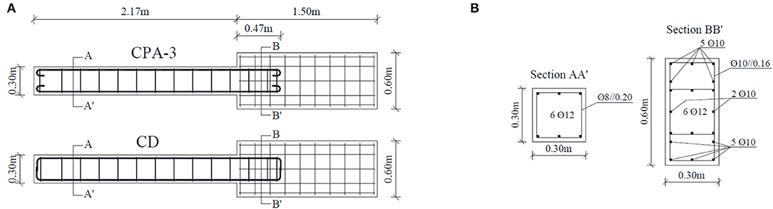
Figure 1. Column specimens: (A) dimensions and reinforcement detailing; (B) cross-sections.
Table 1 presents the mean values of the concrete and steel reinforcement properties, where fcm is the compressive concrete strength of Ø15 × 30 cm cylinder samples, fctm is the axial tensile concrete strength, fym is the yield strength of reinforcement, fum is the ultimate tensile strength of reinforcement, Eym is the reinforcing steel Young's modulus and εsu is the strain at failure.
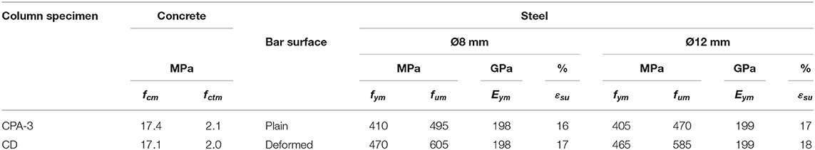
Table 1. Mean mechanical properties of the materials (concrete and steel).
The lateral displacement (dc) history and the imposed loading conditions are presented in Figure 2. The experimental tests were performed under displacement-control conditions. The lateral displacements were applied at column height of 1.7 m (see Figure 2A). The axial load (N) of 305 kN (axial load ratio, ν, equals 19.5%) was kept constant during the tests. The tests were performed in a test-setup where the imposed axial is always centered at the column base (tired rods have fix hinges located at the center of the column base). Therefore, P-delta effects are not considered in the numerical models.
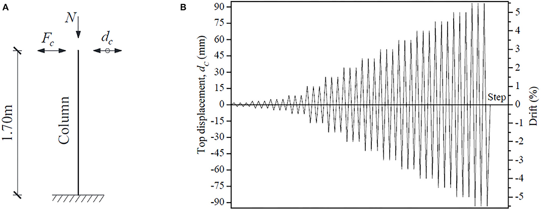
Figure 2. (A) Support and loading conditions idealized; (B) imposed lateral displacement history.
Numerical Modeling With OpenSees
OpenSees (Open System for Earthquake Engineering) is an open source software framework for finite element analysis and performs common fiber-based analysis. The flexural member is represented by unidirectional steel and concrete fibers, which are assumed to be characterized by the selected material stress-strain relationship as adopted by Spacone et al. (2007) in numerical models of RC columns subjected to uniaxial and biaxial loading. The strain of each fiber is obtained based on the section deformation considering the plane section assumption. The fiber strain and stress are updated according to the corresponding material models, followed by upgrading of the section force resultant and the corresponding stiffness (Zhao and Sritharan, 2007).
Four non-linear models were developed for each column, with different linear element types and including or not a zero length section, namely: (i) model with non-linearBeamColumn element (distributed plasticity); (ii) model with BeamWithHinges element (plasticity concentrated over a specified hinge lengths at the element ends); (iii) model with non-linearBeamColumn element and zero-length section element; and, (iv) model with BeamWithHinges element and zero-length section element. The zero-length section element was used to simulate the strain penetration effects and therefore the bond-slip mechanism.
Non-linearBeamColumn Element
The non-linearBeamColumn element considers the spread of plasticity along the element length and is based on force formulation (non-iterative or iterative) (Mazzoni et al., 2007).
BeamWithHinges Element
The BeamWithHinges element contemplates concentrated plasticity at the elements ends (plastic hinges) and is based on the non-iterative (or iterative) flexibility formulation (Mazzoni et al., 2007). In the models under investigation, the length adopted for the plastic hinges correspond to the values observed in the cyclic tests (Melo et al., 2015), which are 0.30 and 0.35 m for the column specimen with plain reinforcing bars and deformed reinforcing bars, respectively.
Zero-Length Section Element
The zero-length section element have a unit-length where the element and section deformations are the same. The unit length assumption implies that the material model of the steel fibers in the zero-length section element represents the slippage of the bars for a given bar stress level. Therefore, a bar stress-slip relationship material model should be assigned to the steel fibers of the zero-length section element.
In the models under investigation, the zero-length section element was placed at the base of the column element, coincident with the node to which were assigned the restraints that simulate the columns' support conditions adopted in the cyclic test. The zero-length section element with the steel model Bond_SP01 were used in combination with the non-linearBeamColumn element or with BeamWithHinges element to simulate the bar slippage. In the numerical results presented in Section numerical results, the bar slippage was only considered in the models with the zero-length section element. In this study, the numerical models consider the bar slippage that occurs in the column plastic hinge and in the foundation (bar anchorage).
Material Models Adopted
The material models Concrete02 and Steel02 were adopted for the concrete and steel reinforcement, respectively. An elastic material with the same elastic modulus of the concrete was used for the elastic part of the BeamWithHinges element. The Concrete02 material model was also used in the concrete fibers of the zero-length section element. The concrete compressive strength improvement due to reinforcement confinement was determinate based on the law proposed by Hognestad (1951) and adapted by Guedes (1997). Moreover, tensile strength was considered in the concrete model. The adopted Concrete02 model parameter values are the same in all models. The adopted values are presented in Table 2, where fcm, fcum, and fctm are the mean values of compressive strength, residual compressive strength (20% of the maximum compressive strength) and tensile strength, respectively. The parameters ε0, εu, and ε0t are the strain corresponding to the compressive, residual and tensile strengths, respectively.
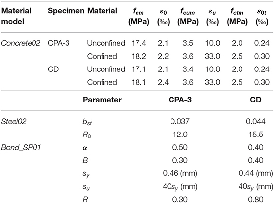
Table 2. Values adopted for the Concrete02, Steel02, and Bond_SP01 model parameters.
The Steel02 model is based on the formulation of Giuffré-Pinto, later implemented by Menegotto and Pinto (1973). The same Steel02 model parameter values were adopted in all models. The steel mechanical properties are in accordance with the mechanical properties present in Table 1. The values adopted for other model parameters are presented in Table 2, where bst is the ratio between post-yield tangent and initial elastic tangent, and R0 is the parameter that controls the transition from elastic to plastic branches.
In OpenSees is available the bar-stress slip model Bond_SP01 that was assigned to the steel fibers in the zero-length section element. This material model was proposed by Zhao and Sritharan (2007) and was developed based on pull-out tests results of deformed steel reinforcing bars anchored in concrete footings with enough embedment length, loaded at the free end side, where was measured the bar stress and end slip evolutions (Zhao and Sritharan, 2007). The adopted model parameter values are indicated in Table 2, where α is a tuning parameter used for adjusting the local bond stress-slip relationship, b is a stiffness reduction, and R is a pinching factor for the cyclic relationship between bar stress and slip. To consider the presence of plain bars, parameter α was made equal to 0.5 in the model of specimen CPA-3, as recommended in (CEB, 1993) for plain reinforcing bars. In specimen CD, the value 0.4 was assumed for parameter α, as adopted by Zhao and Sritharan (2007) in the Bond_SP01 model and recommended in (FIB, 2000). The equations proposed by Zhao and Sritharan (2007) were used to compute the slippage corresponding to the yielding strength (Sy) and ultimate strength (Su).
Numerical Modeling With SeismoStruct
The SeismoStruct is a finite element framework that can be used to predict the large displacements behavior of 3D frames under static or dynamic loading, considering geometric non-linearities and non-linear material properties (Seismosoft, 2018). Several concrete and steel materials models are available to be used in the linear elements.
For each column specimen, two non-linear models were built to simulate the columns response. Similarly to what was adopted for the OpenSees analysis, in one model was adopted the inelastic frame element with distributed plasticity called infrmFB element, whereas in the other model was adopted the inelastic plastic hinge frame element, called infrmFBPH element, with the non-linearity concentrated within a fixed length of the element (plastic hinge). Both elements have a force-based formulation idealized for fiber cross-sections. The SeismoStruct models do not consider the bar slippage effects.
The concrete model con_ma and the steel model stl_mp were adopted in the numerical models. The model con_ma follows the constitutive relationship proposed by Mander et al. (1988) and is a uniaxial non-linear constant confinement model. The material properties adopted in the OpenSees Concrete02 model (Table 2) were also adopted in the con_ma concrete model.
The steel model stl_mp is based on the stress-strain relationship proposed by Menegotto and Pinto (1973) and includes the isotropic hardening rules proposed by Filippou et al. (1983). Table 1 presents the adopted steel mechanical properties. Regarding other model parameters, the default values suggested by SeismoStruct were adopted, except for R0 (parameter that control the shape of the transition curve between initial and post-yield stiffness), which was made equal to 19.5 instead of the default value 20.0.
Numerical Results
This section presents and discusses the numerical analyse results performed to simulate the experimental response of two RC columns (Melo et al., 2015). The numerical results are compared with the experimental ones in terms of force-drift and energy dissipation. The drift is computed dividing the column top lateral displacement by the column height (1.7 m). The dissipated energy evolution is considered as the sum the energy dissipation associated to each cycle, that corresponds to the interior area of the force-displacement loops.
It is recalled that the response of specimen CD is analyzed only up to 3.5% drift, and not until the maximum experimental drift imposed of 5%, due to a data acquisition system problem occurred at the end of the experiment test.
Numerical Results of the Specimen With Plain Reinforcing Bars
The comparison between the experimental and numerical force-drift results, for the column with plain reinforcing bars, is shown in Figure 3. The software platform to performer the numerical analysis, and the linear element model used to represent the column specimen are identified in the graphics.
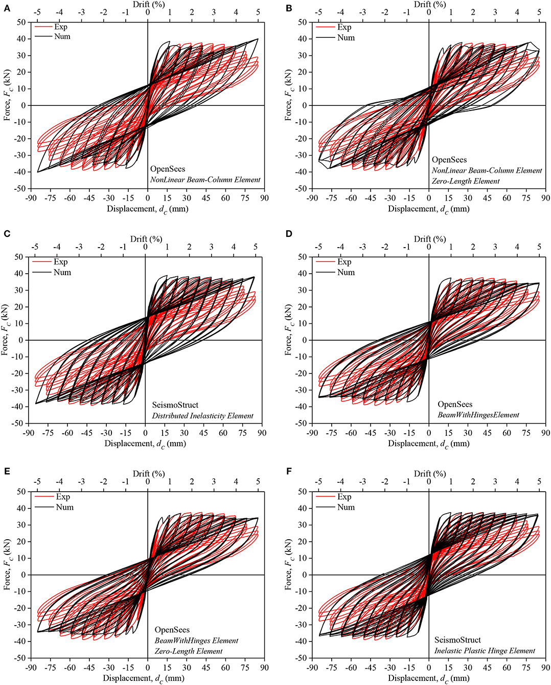
Figure 3. Experimental and numerical force-drift relationship comparison of specimen CPA-3: (A–C) numerical results considering elements with distributed plasticity; (D–F) numerical results considering elements with plastic hinges.
The OpenSees model with BeamWithHinges element (concentrated plasticity) and with the zero-length section element adopted to consider bar slippage gives the best fit to the experimental results.
Conversely, the worst results were obtained in the column with plain reinforcing bars provided by the OpenSees model with distributed plasticity and without considering the bar slippage. It should be noted that any of the models under investigation was able to properly capture the stiffness of the reloading branches, nor the strength degradation, nor the pinching effect.
Considering only the models that do not simulate the bar slippage, the SeismoStruct models with distributed plasticity or concentrated plasticity, provide a relatively better simulation of the column response, when compared to the corresponding OpenSees models, in terms of the maximum strength and ultimate strength (force at maximum drift). However, the initial stiffness is better reproduced in the OpenSees models.
Within the same software, a better simulation was obtained by considering the plasticity concentrated in the plastic hinge regions, instead of distributed along the column' length and was particularly evident in the OpenSees models. This fact is in accordance with the observed damages (large cracks concentrated at the base of the column) in columns with plain reinforcing bars and therefore lower plastic hinge lengths. Thus, the differences in terms of maximum strength and ultimate strength were reduced from 2.7 to 0.5% and from 36.6 to 18.2%, respectively. Adding the zero-length section element to simulate the bar slippage in the OpenSees models, the numerical predictions fits better with the experimental results namely in terms of unloading stiffness and dissipate energy capacity.
The experimental and numerical dissipated energy evolutions are presented in Figure 4. Table 3 shows the ratio between the experimental and numerical values of cumulative dissipated energy at different imposed drift values. All the studied models overestimate the experimental values in terms of energy dissipation, particularly after 1% drift. The OpenSees model with BeamWithHinges elements and zero-length section element gives the best dissipated energy evolution prediction. At the maximum imposed drift, the numerical dissipated energy is 38% higher than the corresponding experimental value.
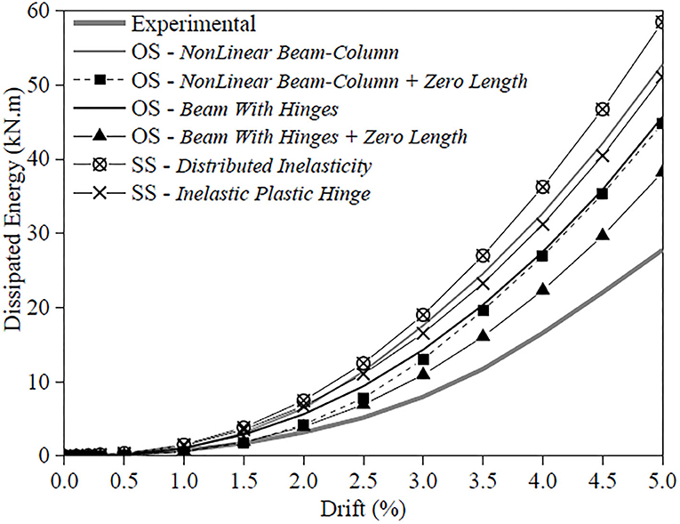
Figure 4. Numerical and experimental dissipated energy evolutions of specimen CPA-3.
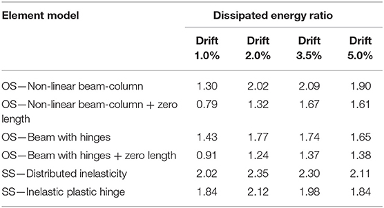
Table 3. Experimental to numerical dissipated energy ratio for different drift levels of specimen CPA-3.
The results obtained with the SeismoStruct model (SS) with distributed plasticity elements gives larger differences. In this case, the dissipated energy obtained by the numerical simulations at the maximum drift is about two times the obtained from the experimental results. As concluded in the force-drift analysis, for this study, better agreement between the experimental and numerical dissipated energy evolution was achieved when is used elements with concentrated plasticity. When the bar slippage effects are considered, the numerical and experimental dissipated energy difference is reduced in about 30%.
Numerical Results of the Specimen With Deformed Reinforcing Bars
Figure 5 compares the experimental and the numerical force-drift relationships obtained for the column with deformed bars. In the graphics, the software platform used to conduct the numerical analysis, and the type of column element used to represent the column specimen are identified.
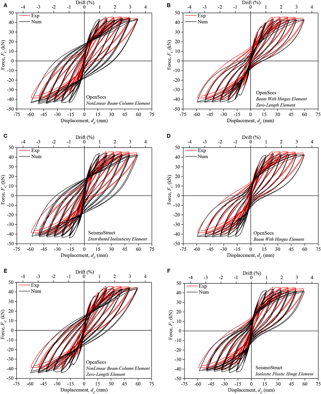
Figure 5. Experimental and numerical force-drift relationship comparison of specimen CD: (A–C) numerical results considering elements with distributed plasticity; (D–F) numerical results considering elements with plastic hinges.
The differences between the numerical results provided by the SeismoStruct models, with distributed plasticity or concentrated plasticity, and those provided by the corresponding OpenSees models are minor, in terms of both force and stiffness. Similarly, to what was concluded for the column specimen with plain reinforcing bars, the best prediction of the column with deformed bars was obtained considering concentrated plasticity instead of distributed along the column' length. In particular, the stiffness reduction evolution is significantly better simulated. The initial stiffness is, however, better simulated in the models with distributed plasticity. Adding the zero-length section element in the OpenSees models led to an enhancement of the results obtained in the numerical simulation in terms of the force-drift envelope.
Similarly to what was concluded for the column with plain bars, the best force-drift prediction (namely in terms of maximum strength) was obtained in the model developed in OpenSees that includes the BeamWithHinges element and the zero-length section element. However, as expected, the influence of the bar's slippage effects in the numerical simulation of the column response, by adopting the zero-length section element, for the column with deformed bars is not as relevant as for the column specimen with plain bars.
The numerical and experimental dissipated energy evolutions are shown in Figure 6. Table 4 gives the ratio between the experimental and numerical values of cumulative dissipated energy at different values of drift. As obtained in the specimen with plain reinforcing bars models, the models overestimate the experimental dissipated energy and the best prediction was obtained with the OpenSees model with BeamWithHinges element and zero-length section element (the model overestimate the dissipated energy by 10% at maximum drift). Conversely, the SeismoStruct (SS) model with Distributed Inelasticity element overestimated in 65% the energy at the maximum drift. When the bar slippage is considered (models with zero-length section element), at the maximum drift, the numerical/experimental dissipated energy differences were reduced in 37 and 28% for the distributed plasticity and concentrated plasticity models, respectively. For the column specimen with plain bars, the corresponding reductions (at 3.5% drift) are equal to 42 and 37%. Therefore, evidencing the importance of considering the effects of bar slippage in the simulation of the energy dissipation evolution for the specimen with plain bars. Based on the results comparison present in Tables 3, 4, the evolution of dissipated energy was generally better reproduced for the specimen with deformed reinforcing bars than for the specimen with plain bars.
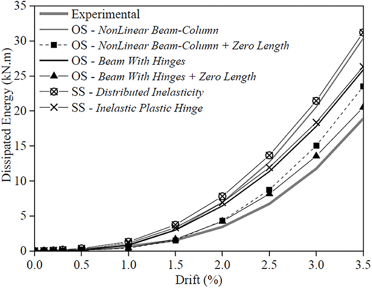
Figure 6. Numerical and experimental dissipated energy evolutions of specimen CD.
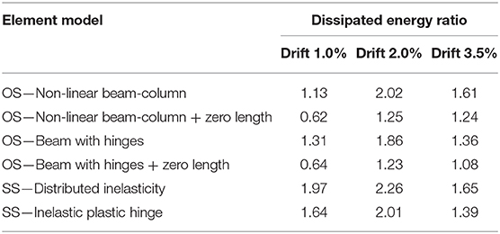
Table 4. Experimental to numerical dissipated energy ratio for different drift levels of specimen CD.
The Modified TRI-Linear Reinforcing Steel Model for Plain Bars
A modified empirical monotonic tri-linear model for the reinforcing plain bars including the slippage effects is here proposed. This simplified model was calibrated against the experimental results of eight columns. The methodology adopted in the model and the comparisons between the experimental and numerical results are presented.
Assumptions and Calibration of the Modified Model
Different strategies can be adopted to incorporate the bond-slip effects in the numerical models. As discussed in section numerical results, one possible strategy is considering a zero-length section. Another possible strategy is including springs along the reinforcing steel bars or in specific sections to simulate concentrated slippage. However, the bar slippage phenomenon develops along the reinforcing bar and cannot be precisely reproduced considering as concentrated in some sections. A simple strategy to contemplate the bond-slip effects along the element length can be modifying the uniaxial steel model by reducing the Young' modulus (Varum, 2003). Decreasing the Young modulus of the steel, the RC elements becomes less stiff and their maximum strength is reached for larger deformations than when real Young modulus is considered.
Figure 7A presents the forces and stresses distribution that are developed in a RC element generic cross-section when loaded in bending and axial load. The concrete and steel fibers forces that occur in the section are dependent of the idealized concrete and steel stress-strain uniaxial laws. The Eurocode 2 part 1-1 (CEN, 2010) parabolic-rectangular stress-strain diagram for confined concrete (Figure 7B) and the bilinear stress-strain diagram idealized for reinforcing steel were adopted in the present analyses. In order to take into account the bar slippage, a modified tri-linear stress-strain diagram is proposed for the reinforcing steel (see Figure 7C). The multi-linear models are commonly used to simulate the behavior of the materials in the fiber section or to simulate the global behavior of a section (Arêde, 1997). By considering the proposed tri-linear steel model, the slippage effects are considered over the all element length and not concentrated in a section as adopted in the models presented in section numerical results and therefore, might simulate better the slippage mechanism, especially in RC elements with plain reinforcing bars.
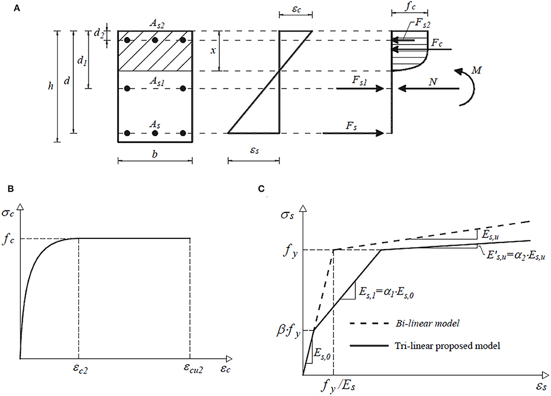
Figure 7. (A) Idealized forces distribution in a section and idealized stress-strain diagrams: (B) concrete; and (C) reinforcing steel.
The modified tri-linear stress-strain diagram is defined by: (i) first branch—represented by the steel Young modulus (Es, 0) up to β·fy, where β is an empirical parameter and fy is the steel yield stress; (ii) second branch—the slope (Es, 1) is obtained multiplying Es, 0 by the empirical factor α1; and (iii) third branch—the slope is given multiplying the original hardening slope (Es, u) by the empirical factor α2.
The analytical expressions that define the moment-curvature relationship for the generic cross-section shown in Figure 7A were developed. The idealized uniaxial stress-strain materials' diagrams presented in Figures 7B,C were considered to compute the section forces (Fc, Fs, Fs1, and Fs2) considering the equilibrium at section level. In this formulation, it is assumed the plain sections assumption.
The experimental moment-curvature diagrams obtained in eight cyclic tests performed on RC columns with plain reinforcing bars (Melo et al., 2015), were used to derive the values of the empirical parameters β, α1, and α2 of the modified tri-linear steel model. The values suggested for the empirical parameters can be used for RC columns with cross-section and reinforcing bar ratios like the eight columns considered in the study. The analytical moment-curvature relationship parameter values that better match the corresponding experimental moment-curvature relationships where derived. Figure 8 shows the cross-section depth and empirical parameter β relationship and the corresponding linear regression with a coefficient of determination (R2) value of 0.96 and it is present in Equation (1), where h represents the cross-section depth in meters.
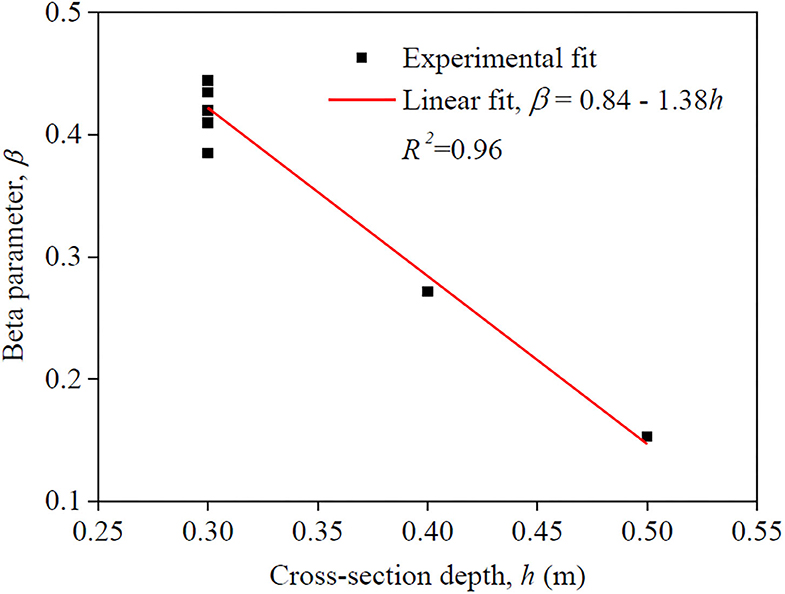
Figure 8. Cross-section depth and parameter β relationship for columns with plain reinforcing bars.
The best experimental fits to moment-curvature relationship for the eight columns with plain reinforcing bars were obtained for α1 = 0.083 and α2 = 0.31 with coefficients of variation (COV) of 0.071 and 0.058, respectively. For the specimen with deformed reinforcing bars the corresponding parameters values are β = 0.45, α1 = 0.25, and α2 = 0.50.
Numerical Validation of the Proposed Model
Two numerical models were developed in OpenSees for the simulation of the envelope of the cyclic response of columns CPA-3 and CD. One model was developed considering perfect bond and the other considering the slippage effects by using the proposed tri-linear steel model. The model that considers perfect bond corresponds to the one presented in the previous section (with non-linearBeamColumn element), but loaded monotonically. For the model that considers the slippage effect, it was used the non-linearBeamColumn element, the Concrete02 concrete model and the Hysteretic model for the steel reinforcement. Hysteretic is a uniaxial multi-linear hysteretic material model, with pinching and degradation of unloading stiffness with ductility demand (Mazzoni et al., 2007). In this case, the adopted values for the material model Hysteretic follows the stress-strain diagram presented in Figure 7C. The parameter values proposed for β, α1, and α2 in the previous section were adopted in this comparative analysis.
Figure 9 compares the obtained numerical monotonic curves (with and without slippage) with the experimental results. The proposed modified steel model adopted in the numerical analyses represents better the experimental results. The benefit of using the modified tri-linear steel model is more clear in the column with plain reinforcing bars (CPA-3). According to Figures 3, 5 and for drift demands ranging from 0.5 to 1.5%, the strength associated to the numerical models without zero-length section element are considerable larger than the strength of the tested columns. Therefore, the proposed simplified steel model improves the representation of the response of RC elements, which is particularly useful for models that do not allow for the inclusion of zero-length section element. This is particularly important for elements subjected to important bond-slip effects, as for RC elements with plain reinforcing bars subjected to large cyclic or monotonic demands.
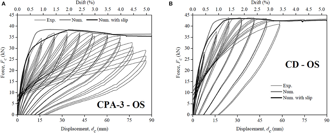
Figure 9. Numerical (with and without slippage) and experimental force-displacement relationships: (A) column CPA-3; and (B) column CD.
Conclusions
A parametric study was developed to investigate the adequacy of different models to simulate the cyclic behavior of two similar RC columns, one built with plain reinforcing bars and another with deformed reinforcing bars. The OpenSees and SeismoStruct frameworks were used to develop the numerical models. In both frameworks, the columns were modeled with non-linear elements with distributed plasticity or concentrated plasticity. The influence of the reinforcing bar slippage was also numerically investigated. For both columns, numerical and experimental results comparisons were established in terms of force-drift relationship and dissipated energy evolution. It is also proposed a modified tri-linear steel material model which considers the slippage of reinforcing bars by reducing the steel Young modulus. Based on this study, the following main conclusions can be drawn:
- Generically, the developed models provide acceptable simulation of the experimental force-drift relationships, but the models were not able to properly capture the strength degradation and the pinching effect, especially for the column with plain bars.
- The results derived from OpenSees and SeismoStruct (considering distributed or concentrated plasticity) are similar for the column with deformed bars.
- For the column with plain bars and disregarding the slippage bar effects, the best results prediction was obtained using the OpenSees model with the concentrated plasticity element.
- For both software, the best experimental and numerical agreements were obtained when the non-linearities are concentrated in the plastic hinge regions, especially for the column with plain reinforcing bars.
- The proposed uniaxial tri-linear steel model led to a better prediction of the experimental response than using a common steel model. This evidence was much more pronounced in the column with plain reinforcing bars, where the slippage is more obvious.
The presented analyses show the importance of bond-slip effects inclusion in the numerical models of RC structural elements with plain reinforcing bars subjected to large demands. Apart from the work already developed, is essential develop additional analyses, based on a larger experimental database, to validate the proposed model. Moreover, the proposed model should be upgraded to be used for cyclic loading.
Data Availability Statement
The raw data supporting the conclusions of this article will be made available by the authors, without undue reservation.
Author Contributions
JM developed and calibrated the numerical models and did the studies to obtain the modified steel model for plain reinforcing steel bars. HV and TR guided JM during the studies and support him. All authors contributed to the article and approved the submitted version.
Funding
The manuscript reports research developed under financial support provided by FCT—Fundação para a Ciência e Tecnologia, Portugal, co-funded by the European Social Fund, namely through the post-doc fellowship of the JM, with reference SFRH/BPD/115352/2016 and by UID/ECI/04708/2019- CONSTRUCT—Instituto de I&D em Estruturas e Construções funded by national funds through the FCT/MCTES (PIDDAC).
Conflict of Interest
The authors declare that the research was conducted in the absence of any commercial or financial relationships that could be construed as a potential conflict of interest.
Acknowledgments
The content of this manuscript has been published partly as part of the thesis of JM (Melo, 2014), and has been presented in part at the 15th European Conference on Earthquake Engineering (Melo et al., 2014). This paper also reports research developed under financial support provided by FCT—Fundação para a Ciência e Tecnologia, Portugal, co-funded by the European Social Fund, namely through the post-doc fellowship of the first author, with reference SFRH/BPD/115352/2016 and by Base Funding—UIDB/04708/2020 and Programmatic Funding—UIDP/04708/2020 of the CONSTRUCT—Instituto de I&D em Estruturas e Construções—funded by national funds through the FCT/MCTES (PIDDAC). The authors acknowledge the staff of the Civil Engineering Laboratory at the University of Aveiro for the support in the preparation and development of the column tests.
References
Arêde, A. (1997). Seismic assessment of reinforced concrete frame structures with a new flexibility based element. (PhD Thesis). Faculty of Engineering of the University of Porto, Porto, Portugal.
Braga, F., Gigliotti, R., Laterza, M., D'Amato, M., and Kunnath, S. (2012). Modified steel bar model incorporating bond-slip for seismic assessment of concrete structures. J. Struct. Eng. 138, 1342–1350 doi: 10.1061/(ASCE)ST.1943-541X.0000587
CEB (1993). Bulletin d'Information N. 217 - Selected justification notes. Comité Euro-International du Béton, April.
CEN (2010). NP EN 1992-1-1. Eurocode 2, Design of concrete structures. Part 1-1: General rules and rules for buildings. Brussels, Belgium: European Committee for Standardization.
Chen, G., and Baker, G. (2003). Influence of bond slip on crack spacing in numerical modeling of reinforced concrete. J. Struct. Eng. 129, 1514–1521. doi: 10.1061/(ASCE)0733-9445(2003)129:11(1514)
De Risi, M. T., and Verderame, G. M. (2017). Experimental assessment and numerical modelling of exterior non-conforming beam-column joints with plain bars. Eng. Struct. 150, 115–134. doi: 10.1016/j.engstruct.2017.07.039
FIB (2000). Task Group 2.5: Bond models; Bond of reinforcement in concrete. State-of-the-art report. FIB Bulletin 10, Lausanne. ISBN 978-2-88394-050-5.
Filippou, F. C., Popov, E. P., and Bertero, V. V. (1983). Effects of bond deterioration on hysteretic behaviour of reinforced concrete joints. Report EERC 83-19, Earthquake Engineering Research Center, University of California, Berkeley.
Governo, D. (1935). Regulamento do Betão Armado (RBA), Decreto n.° 25948, 16 de Outubro, serie I, num. 240, Lisbon, (in Portuguese).
Governo, D. (1967). Regulamento de Estruturas de Betão Armado (REBA), Decreto n.° 47723, 20 de Maio, serie I, num. 119, Lisbon, (in Portuguese).
Guedes, J. M. (1997). Seismic behaviour of reinforced concrete bridges. Modelling, numerical analysis and experimental assessment. (Ph.D. Thesis). Faculty of Engineering of the University of Porto, Porto, Portugal.
Hognestad, E. (1951). A Study of Combined Bending and Axial Load in Reinforced Concrete. Bulletin Series 339. IL: University of Illinois Exp. Sta.
Ioannou, I., Borg, R., Novelli, V., Melo, J., Alexander, D., Kongar, I., et al. (2012). The 29th May 2012 Emilia Romagna Earthquake – EPICentre field observation report. No. EPI-FO-290512, University College London, Department of Civil, Environmental and Geomatic Engineering.
Kwak, H. G. (1997). Improved numerical approach for the bond-slip behavior under cyclic loads. Struct. Eng. Mech. 5, 663–677. doi: 10.12989/sem.1997.5.5.663
Lv, X., Yu, Z., Shan, Z., and Yuan, J. (2019). A stochastic damage model for bond stress-slip relationship of rebar-concrete interface under monotonic loading. Materials 12:3151. doi: 10.3390/ma12193151
Mander, J. B., Priestley, M. J. N., and Park, R. (1988). Theoretical stress-strain model for confined concrete. J. Struc. Eng. 114, 1804–1826. doi: 10.1061/(ASCE)0733-9445(1988)114:8(1804)
Mazzoni, S., McKenna, F., Scott, M. H., and Fenves, G. L. (2007). OpenSees command language manual. Pacific Earthquake Engineering Research Center, University of California, Berkeley, United States.
Melo, J. (2014). Characterisation of the cyclic response of reinforced concrete elements with plain bars. (PhD Thesis). University of Aveiro, Aveiro, Portugal.
Melo, J., Fernandes, C., Varum, H., Rodrigues, H., Costa, A. G., and Arêde, A. (2011). Numerical modelling of the cyclic behaviour of RC elements built with plain reinforcing bars. Eng. Struct. 33, 273–286. doi: 10.1016/j.engstruct.2010.11.005
Melo, J., Varum, H., and Rossetto, T. (2014). “Nonlinear modelling of RC elements built with plain reinforcing bars,” 15th ECEE, European Conference on Earthquake Engineering, Istanbul, Turkey.
Melo, J., Varum, H., and Rossetto, T. (2015). Experimental cyclic behaviour of RC columns with plain bars and proposal for Eurocode 8 formula improvement. Eng. Struct. 88:22–36. doi: 10.1016/j.engstruct.2015.01.033
Menegotto, M., and Pinto, P. (1973). “Method of analysis for cyclically loaded reinforced concrete plane frames including changes in geometry and non-elastic behaviour of elements under combined normal force and bending,” in: IABSE Symposium: Resistance and Ultimate Deformability of Structures Acted on by Well Defined Repeated Loads, Final Report, Lisbon, Portugal.
Monti, G., and Spacone, E. (2000). Reinforced concrete fiber beam element with bond-slip. J. Struct. Eng. 126, 654–661. doi: 10.1061/(ASCE)0733-9445(2000)126:6(654)
Rossetto, T., Peiri, N., Alarcon, J., So, E., Sargeant, S., Sword-Daniels, V., et al. (2009). The L'Aquila, Italy Earthquake of 6 April 2009 – A preliminary field report by EEFIT. London: The Earthquake Engineering Field Investigation Team, University College London, Department of Civil, Environmental and Geomatic Engineering. doi: 10.1007/s10518-010-9221-7
Seismosoft (2018). Seismostruct. Available online at: http://www.seismosoft.com/en/SeismoStruct.aspx (accessed February 24, 2020).
Sezen, H., and Setzler, E. J. (2008). Reinforcement slip in reinforced concrete columns. ACI Struct. J. 105, 280–289. doi: 10.14359/19787
Spacone, E., Filippou, F., and Taucer, F. (2007). Fibre beam-column model for non-linear analysis of R/C frames: part II. applications. Earthq. Eng. Struct. Dyn. 1996, 727–742. doi: 10.1002/(SICI)1096-9845(199607)25:7<727::AID-EQE577>3.0.CO;2-O
Varum, H. (2003). Seismic assessment, strengthening and repair of existing buildings. (PhD Thesis), University of Aveiro, Portugal.
Youssef, M., and Ghobarah, A. (1999). Strength deterioration due to bond slip and concrete crushing in modeling of reinforced concrete members. ACI Struct. J. 96, 956–966. doi: 10.14359/770
Keywords: concrete-steel bond, numerical modeling, plain reinforcing bars, cyclic behavior, RC columns
Citation: Melo J, Varum H and Rossetto T (2020) Numerical Modeling of RC Columns and a Modified Steel Model Proposal for Elements With Plain Bars. Front. Built Environ. 6:586690. doi: 10.3389/fbuil.2020.586690
Received: 23 July 2020; Accepted: 16 November 2020;
Published: 07 December 2020.
Edited by:
Dipendra Gautam, City University of Hong Kong, Hong KongReviewed by:
Enzo Martinelli, University of Salerno, ItalyGiovanni Metelli, University of Brescia, Italy
Copyright © 2020 Melo, Varum and Rossetto. This is an open-access article distributed under the terms of the Creative Commons Attribution License (CC BY). The use, distribution or reproduction in other forums is permitted, provided the original author(s) and the copyright owner(s) are credited and that the original publication in this journal is cited, in accordance with accepted academic practice. No use, distribution or reproduction is permitted which does not comply with these terms.
*Correspondence: José Melo, am9zZW1lbG9AZmUudXAucHQ=