 J. Riley Edwards
 Alvaro E. Canga Ruiz
 Josué César Bastos
 Yubing Liang3
 Marcus S. Dersch
95% of researchers rate our articles as excellent or good
Learn more about the work of our research integrity team to safeguard the quality of each article we publish.
Find out more
ORIGINAL RESEARCH article
Front. Built Environ. , 26 October 2020
Sec. Transportation and Transit Systems
Volume 6 - 2020 | https://doi.org/10.3389/fbuil.2020.582948
This article is part of the Research Topic Best Practices on Advanced Condition Monitoring of Rail Infrastructure Systems, Volume II View all 7 articles
Concrete sleepers are commonly used to constructed ballasted track infrastructure in demanding locations on heavy axle load (HAL) freight railroads with steep grades, sharp curves, and high annual gross tonnage. Center flexural cracking is one of the most common factors limiting the service life of concrete sleepers in North America, and rail seat cracking has also been documented as a performance concern. As such, development and implementation of a structural design method that enables optimization of sleeper design for varied applications and loading environments will reduce initial capital cost and recurring maintenance expense. Field instrumentation has been developed to reliably capture revenue service field flexural demands, facilitating a probabilistic design method for the flexural capacity of concrete sleepers with bending data as the primary input. This paper presents a design process based on structural reliability analysis (SRA) concepts whereby target values for reliability indices (β) for new designs are obtained and compared with existing designs for further design optimization. New (proposed) designs are quite different from current ones. The need for increased sleeper center bending capacity is indicated. Additionally, a reduction in rail seat bending capacity of approximately 40% is justified, reducing the size of the rail seat cross section by approximately the same magnitude. In most cases the proposed designs have fewer prestressing wires and a higher centroid of prestressing steel. In all cases the flexural capacities at the sleeper center and rail seat are better balanced from a structural reliability standpoint. The method proposed is applicable to ballasted track infrastructure constructed with monoblock concrete sleepers.
The flexural design of concrete sleepers is widely considered as the most critical design element, given its direct relationships to the structural integrity and long-term performance of the sleeper. To date, flexural design is based largely on a static analysis of loads, with the application of empirically derived impact factors that vary widely in the international railway engineering community. The primary input into the flexural design of sleepers is the rail seat load, which is considered in conjunction with assumed sleeper support conditions. Quantification of these values has been challenging from an experimental standpoint, thus assumptions are made related to increase in wheel load over static (i.e., dynamic and impact loading), percentage of wheel load transferred to the rail seat under the point of load application, and expected support condition for both center and rail seat regions.
Prevailing international concrete sleeper design practices are deterministic in nature. They rely on load factors to ensure conservatism in design that covers the probabilistic nature of both the loading (demand) and the capacity of sleepers. Additionally, there are no known design practices that require incorporation of empirical field bending moment data, largely due to the scarcity of these data and the challenges associated with interpolation and extrapolation of field results to the variety of applications in which concrete sleepers are used.
In the United States, exceptions to the normal method of design include the application of structural reliability analysis (SRA) to light rail transit sleepers as presented by Canga Ruiz et al. (2020) and research aimed at using field data, and other best practices, to design the next generation of concrete sleepers for Amtrak’s Northeast Corridor (NEC) (Quirós-Orozco et al., 2018). Additionally, reliability analysis methods were developed at the University of Wollongong in Australia (Remennikov et al., 2012). The methodologies presented in this paper extend this preliminary work to a broader set of data from a critical rail transport mode and develops a framework for both the analysis of existing sleeper designs and design of future sleepers using a probabilistic approach based on SRA methods. The research methodology presented in this paper is applicable to the design and performance concrete monoblock sleepers used for initial construction and ongoing maintenance of ballasted track.
Documentation of the need for concrete sleeper structural design optimization in the United States can be found as early as 1970 (RMSA, 1970), coinciding with their initial installation. Since then, the optimization of concrete sleeper design has been pursued through a variety of approaches. Using 2D numerical simulations and some laboratory experimentation, Namura et al. (2005) investigated optimum dimensions of concrete sleepers to minimize ballast stress and sleeper deflection for a Japanese system. Sadeghi and Babaee (2006) performed numerical simulations to optimize an Iranian sleeper by comparing 40 alternative geometrical configurations and choosing the one that minimized flexural demands and ballast pressures. Instead of modifying sleeper geometry, Harris et al. (2011) focused on maximizing the capacity of an existing sleeper’s geometry and concluded that the capacity of an existing sleeper can be increased most efficiently by increasing both the diameter of the prestressing strands and concrete strength (Lutch, 2009).
To efficiently design concrete sleepers, it is necessary to understand the relevant structural design parameters that govern their performance to ensure selection of the correct design philosophy. Worldwide research and the guidance provided by standards and manuals provide useful insight into such parameters. By deploying sleepers instrumented with load cells at the rail seats and the sleeper bottom in various field service conditions, Sadeghi (2008) concluded that dynamic load factors and rail seat loads are accurately estimated by AREMA, but sleeper support conditions are best estimated using UIC (2004) methods. Realizing this deficit, Wolf et al. (2015) built on the earlier findings of McHenry (2013) in an effort to revise AREMA to better account for non-uniform sleeper support conditions when designing for rail seat positive bending, which resulted in updated recommendations in 2017 version of the American Railway Engineering and Maintenance-of-Way Association [AREMA], 2017. You et al. (2017) presented a side-by-side comparison of various standards and recommendations with respect to the most common design variables, including the often-controversial design assumptions for sleeper support conditions. When it comes to design practices, Kaewunruen et al. (2019) documented how many of the most prevalent concrete sleeper design standards can lead to over conservative design solutions, thus generating material waste that could be avoided if dynamic forces and reactions were considered instead of only static (or quasi-static) ones. In most cases, however, standards and manuals lack widespread examples of field collection of sleeper bending moments for the purpose of determining design moment, including the recommendations within AREMA (American), EN 13230 and UIC 713 (European), and Australian Standard AS 1085.14 (Standards Australia, 2003). One such exception is a reference in the European Norm (EN) 13230 (European Committee for Standardization, 2009) that allows for field collection, although this is rarely used in favor of theoretical support assumptions as described in UIC 713R (2004).
As concrete sleeper design practices shift from the traditional allowable stress design to the load resistance factor design, there is a need to establish clear limit states. Kaewunruen et al. (2012a,b) suggested that “the key detrimental factor for prestressed concrete sleepers relies on the ultimate limit state,” as concrete common designs of sleepers tend to easily satisfy serviceability limit states. Murray (2015) considered strength, operations, serviceability, and fatigue as being the limit states necessary for a “rational cost-saving method” of sleeper design. Cyclic loading failure is one aspect that has been considered in this area, including fatigue of steel tendons (Wakui and Okuda, 1997; You et al., 2017), rail seat failure from impact loads (Kaewunruen and Remennikov, 2009), and flexural failure due the interaction of cracks with moisture (Bastos, 2020). Given that controlled center cracking can be accepted in the European context based on language in the prEN 13230-6 (European Committee for Standardization, 2014), fatigue and durability need to be well understood as identified by Zanuy and Albajar (2018), who tested sleepers to investigate their fatigue performance.
Recently, probabilistic design approaches have emerged with a greater focus on structural reliability. Kaewunruen and Remennikov (2009) implemented modern reliability tools to assess the structural safety of prestressed concrete sleepers using the Australian standard AS1085.19 (Standards Australia, 2003) and previous work converting this standard to limit states design format (Remennikov et al., 2007). They used wheel impact load distributions quantified by Leong (2007) to represent the demand model. The capacity model were distributions of rail seat and center flexural stresses, which were generated by combining the effects of 12 random variables. They also considered the reliability at transfer of prestressing forces (initial stage) and the reliability indexes for steel wires. Soltanian et al. (2018) developed a probabilistic model for time dependent reliability analysis for prestressed concrete sleepers subjected to corrosion in aggressive chloride environments.
Remennikov et al. (2012) presents an approach that infers rail seat loads, and resulting flexural demands, from Wheel Impact Load Detector (WILD) data. This process, when combined with the preceding research mentioned above that informed it, is the most robust concrete sleeper design method proposed to date, considering both field loading and design capacity in a probabilistic manner. The inference of rail seat loads from WILD data (Van Dyk et al., 2014), however, leaves room for error. Results from field experimentation have shown substantial variability in the percentage of wheel load that is transferred to the rail seat beneath the point of load application (Edwards et al., 2017a,b). This research also found that even small gaps (less than 1/4 in.) between the sleeper and ballast can result in wide variability in applied rail seat loads and bending moments. Controlled laboratory experimentation, varying support conditions, and quantifying their impact on bending has also been undertaken to demonstrate how bending moment demand is sensitive to support conditions (Bastos, 2016; Bastos et al., 2017). Research has also shown that variability in temperature can affect field bending moments (Wolf et al., 2016b; Canga Ruiz, 2018; Edwards et al., 2018; Canga Ruiz et al., 2019), which is another factor that is not considered in a method that relies solely on input loading at the wheel rail interface to calculate flexural demand.
Bending moment variability is due to a variety of factors that relate to the stiffness of the track structure, the uniformity of ballast beneath the sleeper, and the external (train-induced) loading level on the sleepers. The effect of these predictor variables was investigated in previous research by Edwards (2019). Additionally, the relationship between wheel loads and rail seat loads, and thus bending moments, is non-linear, as shown by Prause and Kish (1978) and more recently by Gao et al. (2017) and Quirós-Orozco (2018). This finding further demonstrates the importance of using bending moment data as the primary input into a design process for concrete sleepers and not being reliant on functional relationships between wheel loads and bending moments. These findings indicate that the topic of bending moment variability warrants additional research to holistically quantify moments under a variety of operating and loading conditions.
The concept of probabilistic design was proposed within the United States rail industry by Kalay and Samuels (2002) in the context of reducing the “stress state of the railroad” and there are international examples of the emergence of probabilistic design dating back to the 1970s (Heath et al., 1972). Stress state reduction in general, and the specific application of sleeper design lends itself to a probabilistic analysis. Their proposed approach viewed changes to track infrastructure design, rolling stock gross rail load, and wheel condition in terms of its impact on either the stress (i.e., demand) or strength (i.e., capacity) of the system. SRA is a well-developed and documented method (Ang and Tang, 2006), which has been frequently applied to structural design (Soares, 1997; Elishakoff, 2017). The field of SRA continues to evolve (Frangopol et al., 1997; Der Kiureghian, 2008; Steenbergen et al., 2013) and provides a viable method for assessing the design of many types of structural elements, including sleepers, further substantiating the need for, and feasibility of, a probabilistic design approach.
Concrete sleepers must be designed to fulfill a variety of performance requirements; ensuring their flexural capacity, base pressure, lateral resistance, and rail seat abrasion resistance are adequate for the loading demands placed on them. To date, there has been no comprehensive application of SRA methods to concrete sleeper flexural design using field-collected bending moments as the input for generating a demand model, although an initial analysis by Canga Ruiz et al. (2020) was undertaken to demonstrate the viability of such an approach for light rail transit. Beyond the aforementioned research related to concrete sleepers, there has been limited probabilistic consideration of the analysis of the track substructure and its behavior (Lee, 2013) and a track superstructure application related to the performance of rail steel, albeit in terms of risk assessment and not rail strength or sectional design (Jamshidi et al., 2017).
The best input into an SRA, or probabilistic design methodology, for the flexural capacity of concrete sleepers are field data representative of the actual flexural demands. Such a methodology has been developed (Edwards et al., 2017b) and deployed by researchers at UIUC to answer a variety of engineering questions related to sleepers and the field moment demands placed on them (Wolf et al., 2016b; Canga Ruiz, 2018; Edwards et al., 2018; Quirós-Orozco et al., 2018; Canga Ruiz et al., 2020).
The application of SRA and probabilistic design for the analysis and design of concrete sleepers is interesting from an academic standpoint for several reasons. First, large variation in loading conditions are generated by a variety of different types of railroad rolling stock and a wide range of wheel conditions and resulting impact loads (Van Dyk, 2014; Van Dyk et al., 2014). Second, the occurrence of both positive and negative bending at the rail seat (Prause and Kish, 1978; Edwards et al., 2018) and center (Wolf et al., 2016a; Edwards et al., 2018) cross sections due to differing sleeper support conditions is of interest and is largely absent from other prestressed concrete applications. Finally, the availability of large quantities of reliable demand data collected using field instrumentation is unique. The benefits of reducing sleeper cross-sectional area are primarily due to manufacturing (first) costs, but there are also benefits accrued from reducing the level of pre-tensioning (i.e., being able to design to lower bending moments), thus reducing the stress state of the sleeper and mitigating failure modes such as end splitting.
As an initial step toward concrete sleeper probabilistic design, and to quantify the potential value in pursuing such a method, we undertake a quantitative evaluation of the center flexural capacity of existing sleeper designs using SRA methods similar to what was demonstrated by Canga Ruiz et al. (2020) for another rail transit mode. It is important to note that there is a difference between the design specification value and actual flexural capacity of a sleeper. This difference represents an internal safety factor that concrete sleeper manufacturers apply to ensure that even their “weakest” sleepers exceed the design value specified by the end user to minimize rejection of product due to inadequate flexural capacity.
Additionally, a portion of this differential may be due to the discrete nature of key inputs in the sleeper design and manufacturing process (e.g., an integer number of wires can be used, finite grades of prestressing steel, etc.). Beyond this safety factor, results from previous field experimentation have indicated that there is significant excess design capacity (actual capacity exceeding service demand), highlighting the need for optimization of sleepers and the selection of a probabilistic design method (Wolf et al., 2016a; Edwards et al., 2017b, 2018; Quirós-Orozco et al., 2018). This is especially true for rail transit sleepers (Edwards et al., 2018).
Prevailing international concrete sleeper design standards are static in nature and rely on the use of deterministic parameters for estimating both the demand and capacity of concrete sleepers. The demand is augmented with dynamic and impact factors to increase the static bending moment. The capacity is augmented by applying safety factors to account for variability in this deterministic application. The specific values used to incorporate variability and estimate capacity and demand are often derived through trial and error, occasionally supported by experimental results.
For the probabilistic design method described in this paper, bending moment is the metric used, measured in kip-inches (kN-m in SI). This is due to the fact that bending moments are the most widely used metric to quantify the “strength” of concrete sleepers. Sleepers behave as beams (transverse loads are applied causing them to bend), thus are considered as flexural members. Additionally, probability density functions (PDFs) are used as the primary means of visualizing bending moment data.
The first element in the SRA process employed in this research is the assessment of concrete sleepers to obtain reliable field data that represent the flexural demands placed on concrete sleepers. These data need to be collected at both the center and rail seat sections given that both regions are critical sections that warrant independent design analysis using a sectional method (Bastos, 2016).
To quantify sleeper bending moments, concrete surface strain gauges were deployed in the field during revenue service train operation. This method was previously developed, deployed, and validated under heavy axle load (HAL) freight operations (Edwards et al., 2017b). The calibration process uses the relationship described in Equation 1 to relate a known bending moment to the concrete sleeper’s sectional properties and response to load:
Where:
Ms is the sleeper bending moment at section “s,” kip-in (kNm),
εs is the strain measurement from the surface strain gauge at section “s,” in/in (mm/mm),
Ec is the elastic modulus of the concrete, psi (kPa),
Is is the moment of inertia at section “s,” in4 (mm4),
ds is the distance from the surface strain gauge to the neutral axis of bending of the sleeper at section “s,” in. (mm).
Section “s” refers to the cross-section of the sleeper where the strain gauge is located, which must be consistent between the calibration sleeper and the test sleeper in the field. The terms Ec, Is, and ds are unique to the sleeper and are determined in an aggregate fashion through laboratory calibration. For the sleepers described in this manuscript the laboratory calibration factors were found to be 790,928 kip-in/ε (89,363 kNm/ε), 591,921 kip-in/ε (66,878 kNm/ε), 684,533 kip-in/ε (77,342 kNm/ε), for Gauges A, C, and E, respectively.
In order to quantify the flexural behavior of the sleeper under load, bending strains were measured at critical locations along the length of the sleeper (Edwards et al., 2017b). Concrete surface strain gauges were applied oriented longitudinally along the chamfer near the top surface of the sleeper. For some of the sleepers at each field-testing location, five strain gauges (labeled A–E) were applied, with one at each of the two rail seats, one at the center, and another located approximately halfway between each rail seat and the sleeper center (Figure 1). The research discussed in this paper, related to flexural design of sleepers, will only draw upon data from Gauges A, C, and E (i.e., center and rail seats).
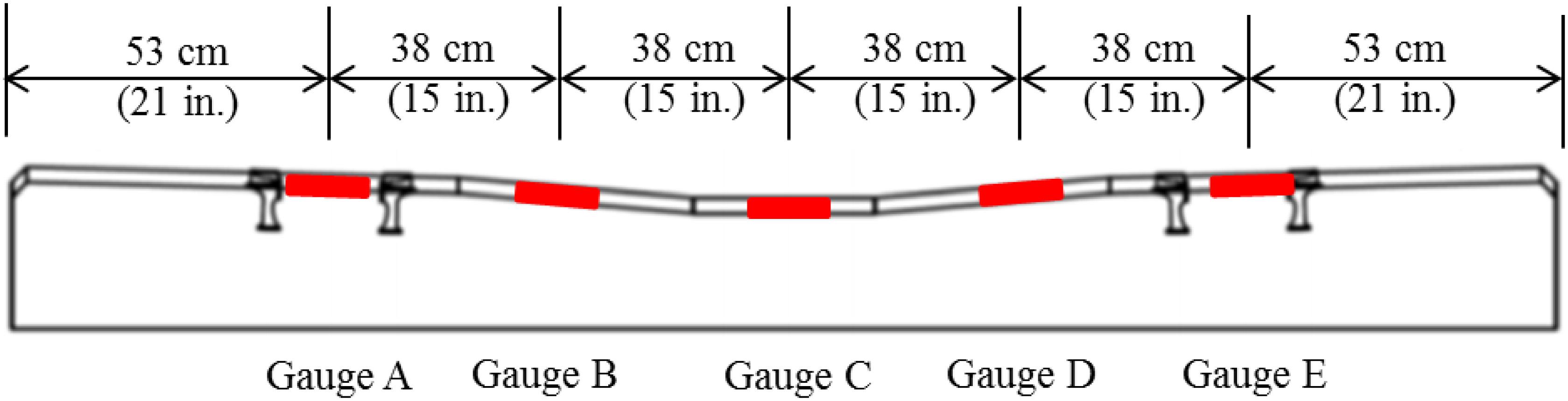
Figure 1. Profile view of sleeper showing locations of strain gauges (Wolf, 2015).
The dimensions shown in Figure 1 account for a specific instrumented sleeper with a total length of 102 in. (258 cm), a common sleeper type used in North America on HAL freight railroads. Images of instrumented sleepers in the field with fully protected gauges can be seen in Figure 2.
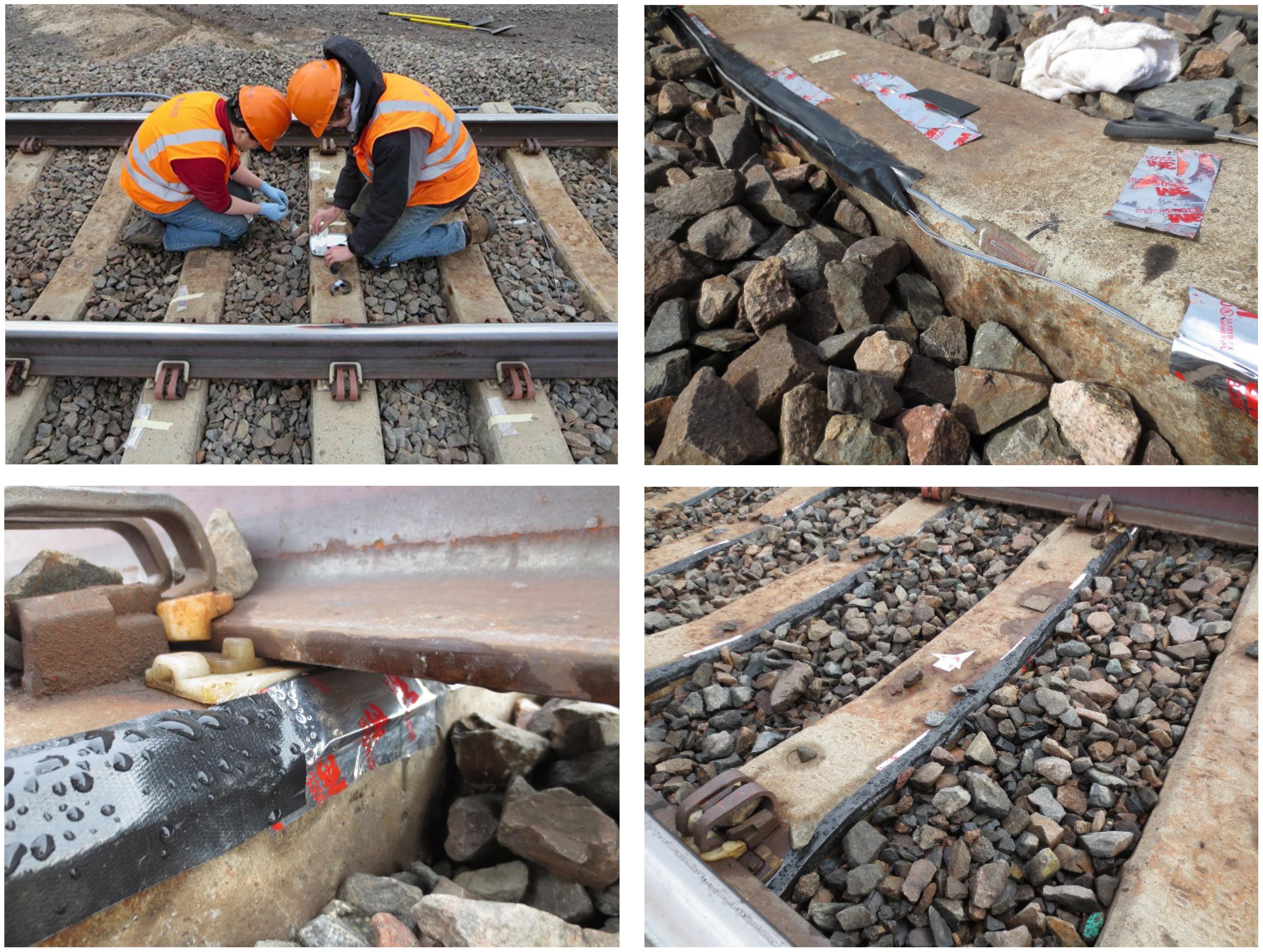
Figure 2. Images of sleepers instrumented with concrete surface strain gauges at a HAL freight railroad field experimentation location.
Further information on the deployment of instrumentation is described in Edwards et al. (2017b). Table 1 also includes the owner-provided “specification” value that must be met or exceeded to avoid sleeper cracking. Design values represent the first crack capacities associated with the unique sleeper designs that are supplied by the sleeper manufacturers. To relate the field-measured strains to center and rail seat bending moments, calibration factors were generated through laboratory experimentation at UIUC’s RAIL per the methods described by Edwards et al. (2017b).
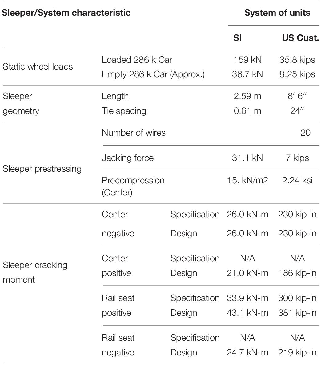
Table 1. Characteristics of HAL freight railroad loading conditions and sleeper structural geometric properties for the locations considered in this study.
The field instrumentation and data collection discussed in this paper were conducted on ballasted track locations on a high-density mainline HAL freight railroad location in the western United States (hereafter referred to as “HAL freight”). Because of the observed variability of support conditions observed in past field experimentation (Wolf et al., 2015; Gao et al., 2016; Edwards et al., 2017a,b), and knowledge of load dispersion (Hay, 1982; Kerr, 2003; Van Dyk, 2014), data were collected and processed from multiple consecutive sleepers. Thus, instrumentation was placed in two locations, or “zones,” of tangent track, spaced approximately 60 ft. (18.3 m) apart on center (Figure 3).
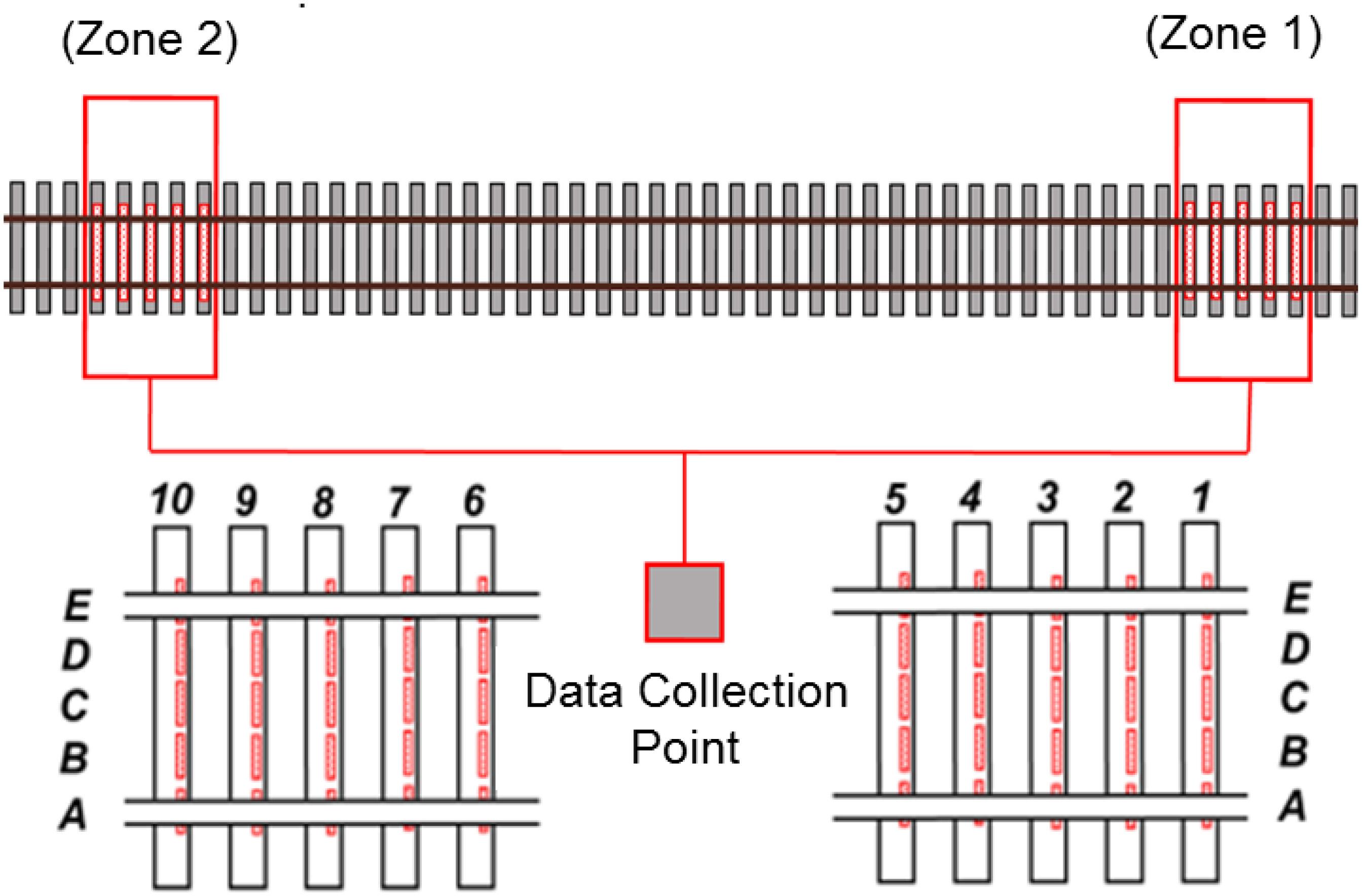
Figure 3. Field site layout with ten sleepers in two test zones (Wolf, 2015).
A dataset containing a random sample of approximately 5,000 center and rail seat bending moment observations were extracted using simple random sampling without replacement to generate unbiased datasets for the center and rail seat demand models. These data were extracted from a larger set containing approximately 142,600 and 138,000 center and rail seat bending moment observations (Figure 4). Research by Edwards (2019) provided confidence that the data set is representative of the population.
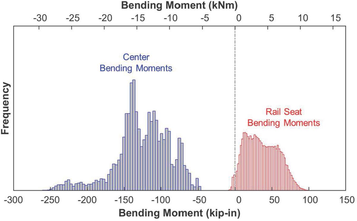
Figure 4. Histogram of raw data of sleeper rail seat and center bending moments used to generate demand models for HAL freight.
To develop bending moment demand distributions and establish fitted curves for further analysis, data were analyzed in MATLAB and the commercially available software EasyFit (by MathWave Technologies). EasyFit considers 65 of the most common distributions (e.g., log-logistic, Gamma, normal, Weibull, etc.) and facilitates the estimation of parameters for fitted PDFs and cumulative distribution functions (CDFs). To evaluate the adequacy of the fit of the selected distributions both the Kolmogorov–Smirnov (K–S) and Anderson–Darling tests were employed.
As compared to the K–S test, the Anderson–Darling test has advantages that are applicable to the engineering questions being considered here. The Anderson–Darling method is especially useful for this application because it increases the power of the K–S statistic to investigate the tails of the distribution and produces a weighted statistic (Darling, 1957; Press et al., 2002; Engmann and Cousineau, 2011). Additionally, there is evidence that the Anderson–Darling test can detect very small differences in the goodness of fit for distributions, even for large sample sizes such as what are used for this research (Engmann and Cousineau, 2011).
Focusing on the tail is important given our application for the design of future railway track infrastructure components. Current structural engineering design methodologies consider Ultimate Limit State (ULS) to bound the failure conditions of a structure using an extreme event that is defined depending on the function of the structure. In a similar fashion, this paper aims to better address the design for failure of concrete sleepers, thus being of paramount importance the understanding of the most demanding, yet most infrequent, loading scenarios. The best-fit (optimal) distribution was then selected using the Anderson–Darling criteria, with priority given to distributions that are more commonly recognized, and of a lower order (e.g., avoidance of three or four parameter models).
Table 2 summarizes the best fit for each of the data sets collected, as indicated by the Anderson–Darling test criteria. The majority of the best-fit models contained two and three parameters. Additionally, Table 2 contains the distribution types, PDF functions, and parameter estimates for each model.
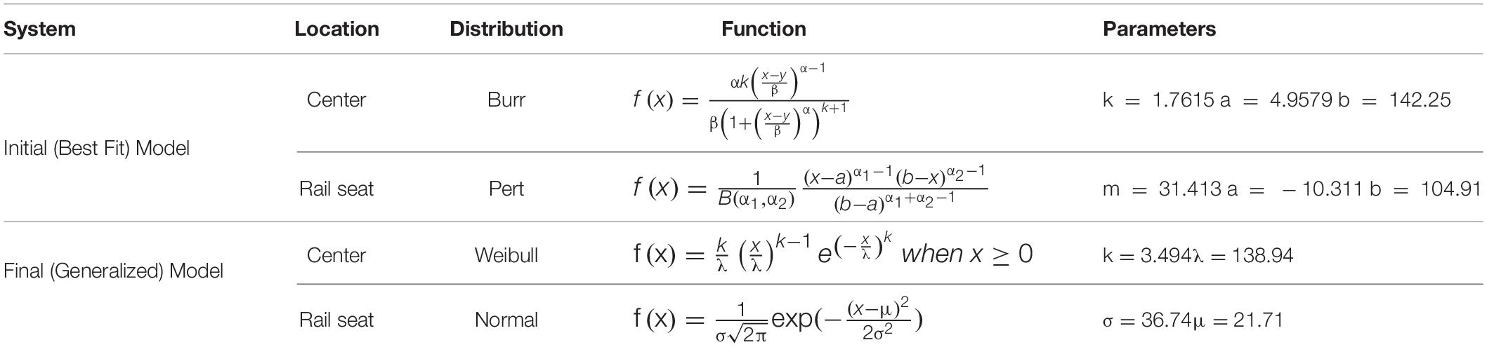
Table 2. Descriptions for best fit and final demand models, with equations and parameters.
While the “best” fit distribution is most useful for modeling the flexural demand of a specific HAL freight railroad system, a more general distribution for representing the data is useful for widespread application of the demand curves and the broader probabilistic methodology described in this paper. This is due in part to the fact that distributions with more than two parameters are likely overfitting (Kutner et al., 2005) the existing field demand data to reflect the specific attributes of a given rail transit system.
As such, and as shown in the bottom two rows of Table 2, the selection of a Weibull distribution for center moments and a normal distribution for rail seat moments is deemed most practical. These two distributions were selected due to widespread knowledge of their use. Additionally, the normal distribution is reflective of the uniform nature of rail seat bending moments given that they are not as sensitive to variable support conditions. Weibull distributions were generated in the context of engineering and fatigue analysis and excel at representing extreme events (Weibull, 1951), an attribute of the center bending moment data that must be considered. In Figure 5, the selected distributions are overlaid on the histograms of raw data.
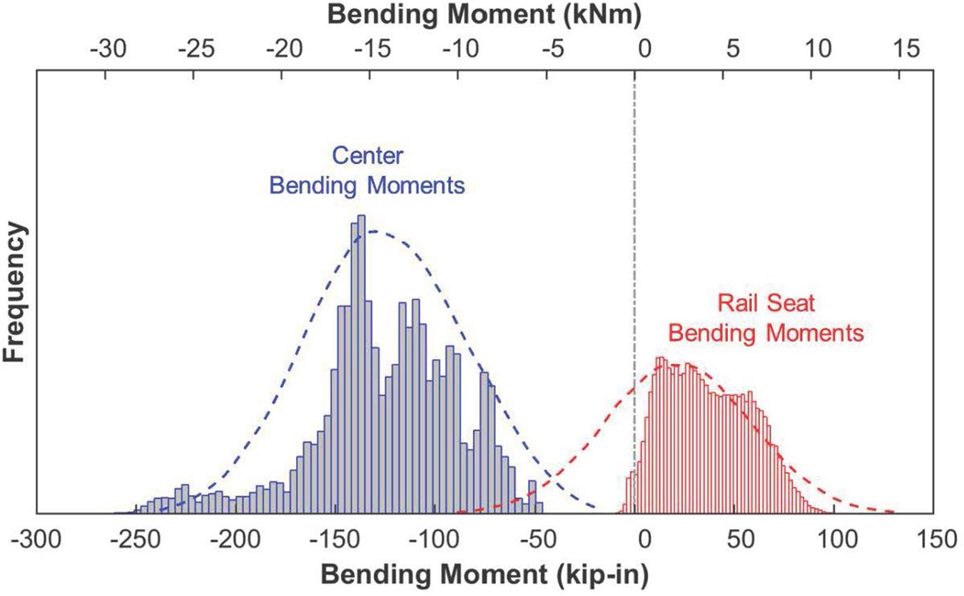
Figure 5. Fitted PDFs overlaid on raw data of sleeper rail seat and center bending moments used for demand models for HAL freight.
The authors understand the influence of accurate curve fitting on SRA model results and have thus compared curves obtained from the field data reported in this manuscript to other field data to ensure consistency in the type and fit of distribution. To further improve the demand model, data collected at discrete field sites could be extrapolated to consider a variety of other support conditions that could be present over the entire railway network. Such an extrapolation was documented by Quirós-Orozco et al. (2018) in conjunction with the redesign of Amtrak’s concrete sleeper for the Northeast Corridor (NEC). The study of support condition variability is non-trivial, and the cost of obtaining a holistic understanding of an entire rail corridor would be substantial. For purposes of this research, the demand curves listed above will be used.
There is also a time dependency in the demand curve. Factors influencing this are initial construction loads (e.g., ballast trains on track with no ballast layer that may be placed on a crowned sub-ballast) and the time and tonnage dependent deterioration of track support conditions. Other than hand calculations to confirm the former, and pilot projects to quantify the latter (Wolf, 2015), these factors are largely unquantified and require separate study.
Most prestressed concrete sleepers in the United States are designed as Class U (uncracked) members using the American Concrete Institute (ACI) Building Code Requirements for Structural Concrete and Commentary, ACI 318-14 (American Concrete Institute [ACI], 2014). Their flexural capacity is defined based on first crack, typically occurring at the extreme tensile fiber (e.g., top center of sleeper in center bending). This is similar to what AREMA MRE, Chapter 30 (2017) states except that AREMA requires a crack to penetrate to the first level of prestressing from the tensile surface of the sleeper.
As such, the total stresses at the extreme tensile fiber cannot exceed the modulus of rupture (fr) of the concrete (Equation 2), an empirically derived limit that provides an indirect measure of concrete’s tensile capacity. The three terms in Equation 2 represent precompression, the internal moment caused by the eccentricity of prestressing, and the external moment due to passing wheel/axle loads.
Where:
fr = modulus of rupture of concrete (ksi) [0.627 ksi for of 8 ksi],
Mc = center negative bending moment (kip-in),
Fse = effective prestressing force (after losses) (kips),
Ac = cross-sectional area (in2),
Ic = section moment of inertia (in4),
e = eccentricity of prestress centroid (in.),
c = distance from neutral axis to extreme fiber (in.).
For concrete with a compressive strength () of 7 ksi (typical for concrete sleepers) the value for fr is 0.627 ksi according to Table 24.5.4.1 in ACI 318-14 (American Concrete Institute [ACI], 2014). The modulus of rupture is likely higher for high strength concrete, but absent sufficient experimental data to refine this limit, we have chosen to follow the ACI formulation as a lower bound. The strength of a prestressed concrete member is typically governed by cracking at the tensile surface, not crushing in the compression region due to the manner in which it is loaded (e.g., uniform load or two distributed rail seat loads). McNeely and Lash (1963) suggests use of distributions for fr with a standard deviation of 8.5% based on experimental results from split tensile tests on cylindrical specimens.
Compared to the tensile strength, the crushing limit for concrete is much higher, on the order of 4.2 ksi for concrete with a compressive strength () of 7 ksi according to ACI 318-14 (American Concrete Institute [ACI], 2014). Literature also indicates that the fatigue life of concrete should be considered, but the inclusion of concrete fatigue criteria into this largely static design process and evaluation is challenging (American Concrete Institute [ACI], 1997). In general, fatigue limits are more conservative than the 0.6 limit, and are recommended in the range of 0.2 to 0.4 (American Concrete Institute [ACI], 1997). This does not seem reasonable with respect to the present application, thus no additional reduction of concrete’s compressive strength will be considered for fatigue. As noted in ACI 318-14 (American Concrete Institute [ACI], 2014) section R24.5.4.1, fatigue tests on prestressed concrete beams have shown that the compressive failure of concrete is not the controlling criterion.
The limit state values for both tensile and compressive strength of concrete specified by ACI 318-14 (American Concrete Institute [ACI], 2014) are conservative. This is especially true for compressive strength, which is reduced by 40%. Future research should include a sensitivity analysis in which the strength reduction factors are varied within reasonable ranges based on data from prior experimentation.
To align with conventional mechanics terminology, compressive stresses are characterized as negative, and tensile stresses are positive. Additionally, the negative second term in Equation 2 () indicates that the eccentricity induced by the prestress produces compression in the top of the sleeper that is used to counteract a positive bending moment. The stresses listed in Equation 2 can also be represented graphically for the case of center negative bending.
The critical stress-related value that must be quantified in order to identify when the structural member will fail, is the bending moment, as indicated earlier. Equation 3 is generated by solving Equation 2 for the cracking moment that would indicate that the total stresses in the tensile surface equal the modulus of rupture (fr), which defines the maximum moment capacity at first crack at a given section.
Where:
Mcr = cracking moment (kip-in);
ctens = distance from neutral axis to extreme tensile fiber (in).
For brevity, only the sleeper center region was considered when providing a background to prestressed sleeper design, and the tensile (top) surface will be the location of greatest attention. The rail seat flexural considerations are similar, although limited by tension on the bottom surface of the sleeper as a result of positive bending moments. The “minor” bending moments, rail seat negative and center positive, are also considered using this same method but with minor modifications listed below.
The proposed process will generally follow a procedure in which limit state functions define the boundary between failure and functionality of a component. This represents the location in which the capacity and demand model cancel each other as shown in Equation 4.
Where:
x1 denotes the vector of random variables which define capacity;
x2 denotes de vector of random variables that define the demand;
x denotes the vector of random variables combination of x1 and x2;
g(x) denotes the limit state function;
C(x1) denotes the capacity model;
D(x2) denotes the demand model.
Thus, when the limit state function has a negative result, failure occurs, as the induced demand exceeds the provided capacity of the concrete sleeper. The probability of failure is based on the likelihood of the demand [D(x)] being greater than the capacity [C(x)], as indicated by the overlap of the two curves. This methodology facilitates evaluation of current designs, and can also be applied to development and optimization of future designs. For reference, earlier probabilistic design literature has referred to the curves using the terms of resistance (R) and load effect (Q) (Szerszen and Nowak, 2003).
As a part of this application of the SRA methodology, limit state equations for each of the critical design cross sections were derived, that map to the stress level at top and bottom fibers of the sleeper based on AREMA (American Railway Engineering and Maintenance-of-Way Association [AREMA], 2017) and ACI 318 (American Concrete Institute [ACI], 2014). These equations define the transition of the component from functional to failed and were previously documented by Canga Ruiz et al. (2020). Failure is defined as “cracked.” Equations 5 and 6 represent limit state equations at the top and bottom of the center cross section, respectively.
Similarly, Equations 7 and 8 represent the rail seat limit state equations at top and bottom, respectively. In Equations 5–8, the capacity of the material is represented in the first time on the right of the equality and the demand is calculated using the remaining terms.
Additionally, there are four more equations for g5(x) through g8(x) (Equations 9–12) that represent the lesser bending moments that can be induced at the center (positive) and rail seat (negative) that are not shown in this paper for the sake of brevity.
Equations 5–12 are then used as limit state functions for a first order reliability method (FORM) analysis to generate reliability indices (Zhao and Ono, 1999). To solve the problem using FORM, a MATLAB (2012) toolbox created by the University of California Berkeley for SRA topics to conduct the simulation was used (Der Kiureghian et al., 2006).
The factors considered in the analysis are listed in Table 3, along with the type of distribution and its simple statistics. Concrete compressive strength was obtained from prevailing concrete sleeper specifications. Compressive strength distribution characteristics were obtained by a review of relevant literature (Bartlett and MacGregor, 1999; ACI Committee 214, 2002; Mertol et al., 2008; Remennikov et al., 2012; Nowak and Collins, 2013; Rakoczy and Nowak, 2013, 2014). The jacking force value of 7 kips (75% of prestressing steel ultimate capacity) and resulting losses were estimated based on the ACI 318-14 (American Concrete Institute [ACI], 2014) assumption of 15% total losses and a reasonable standard deviation associated with the process of stressing wires and its inherent complexity.
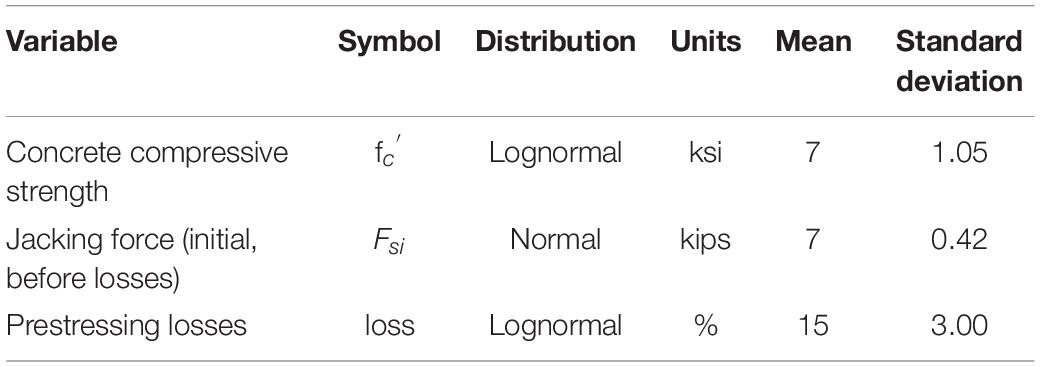
Table 3. Random variables used in concrete sleeper flexural capacity models.
To provide a graphical output of an aggregate capacity curve that can be compared to the field demand curve, Monte Carlo Simulation (MCS) was used. Using MCS, the distribution of possible flexural capacities was generated by using approximately 10,000 iterations that can be considered representative of the population. The method by which data were selected within the MCS was direct sampling. This method is appropriate given the fact that the input variables are all independent and there is no correlation among them. Beyond this graphical representation generated using MCS, FORM, and second order reliability methods (SORM) are considered to be more accurate methods to execute an SRA (Frangopol et al., 1997; Zhao and Ono, 1999). Due to the linear nature of this work, SORM does not improve the results (Canga Ruiz, 2018), thus FORM was deemed appropriate and reliable.
Figures 6, 7 present graphical results from the MCS of the sleeper design under consideration, showing both rail seat and center sectional results for both positive and negative bending moment applications. To represent the field data, Weibull and normal distributions were chosen (Table 2).
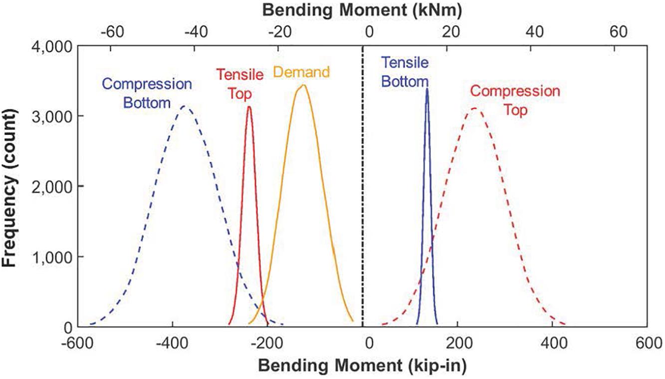
Figure 6. Results from MCS of sleeper center bending moments for HAL freight.
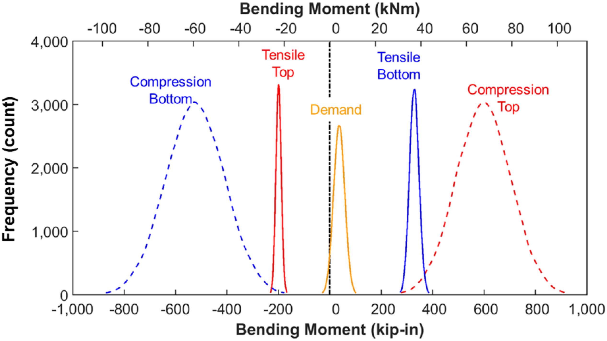
Figure 7. Results from MCS of sleeper rail seat bending moments for HAL freight.
In the field of SRA, the probability of failure is quantified using a “reliability index,” defined as “β.” This term is functionally related to the probability of failure (Pf), as shown in Equation 13 (Ditlevsen and Madsen, 2007; Nowak and Collins, 2013).
Where:
Φ–1 represents the inverse of the standard normal cumulative distribution function.
Pf represents the probability of failure.
Table 4 includes individual values for the reliability indices (β) that represent failures in either positive or negative bending at the center and rail seat sections. The results indicate the design imbalance in terms of probability of failure between the center and rail seat sections, with a far greater design robustness for the rail seat section. Greater uniformity of probabilities of failure at both the center and rail seat is desirable, and will be the focus of the parametric study described in Part 5.
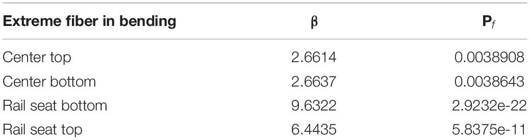
Table 4. Reliability index and probability of failure for the studied limit state functions obtained using FORM.
The aforementioned analysis is based on the flexural strength at initial concrete cracking, and not the component’s ultimate capacity or some location within the transition zone that is also specified by ACI 318-14 (American Concrete Institute [ACI], 2014). As discussed previously, this definition differs from the American Railway Engineering and Maintenance-of-Way Association [AREMA] (2017) definition, which does not define a sleeper as failed until the crack has penetrated from the tensile surface to the first level of prestressing steel. In the future, the residual capacity could be defined in reference to ultimate capacity, which is approximately double the cracking moment capacity as demonstrated experimentally by Bastos et al. (2017, 2018).
For design, the same demand model that was used in the analysis of existing designs will be employed, given that the data are representative of conditions likely to be encountered in the field. The demand model could be further refined to consider a variety of possible support conditions. This requires additional assumptions and is a topic that warrants further research.
The capacity models are generated using FORM, while incrementally changing sleeper geometry (height and width), number of prestressing wires, and prestress centroid within the bounds that are described in Table 5. The initial models were run at coarser increments for sleeper geometry, and subsequently re-run at a finer increment [0.25 in (6.35 mm)]. Final model increments were also selected to be compatible with reasonable prestressed concrete manufacturing tolerances.
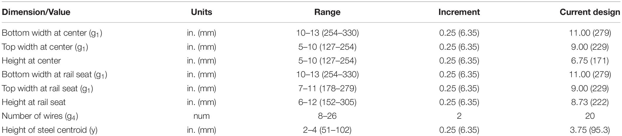
Table 5. Bounds for sleeper design deterministic input parameters.
Additional constraints placed on the model are infeasible cases in which (1) the sleeper top width exceeds the bottom width at either the rail seat or center, (2) the centroid of steel is less than the height of centroid of concrete at the center, and (3) the location of the centroid of steel is greater than the height of centroid of the concrete at the rail seat. For each set of discrete design variables selected, the random variables in Table 5 were simulated using FORM. The result of each simulation of the various design permutations were reliability indices (β) at the sleeper center and rail seat regions.
For selection of the optimized design, the authors assumed values for β that are representative of the current state of practice in the United States. Szerszen and Nowak (2003) concluded that the ULS of prestressed beams designed using ACI 318 (American Concrete Institute [ACI], 2014) have an equivalent β ranging from 4.2 to 4.4. These values were calculated by varying material, geometry and load values, and resulted in a target reliability index (βT) of 3.5. This research utilizes a previous approach that treated load and resistance parameters from ACI as random variables to statistically determine reliability indices (Szerszen and Nowak, 2003) which is described by Nowak and Collins (2013). This equivalent β defines what is an acceptable design following the concrete structures design code in the United States (Nowak and Collins, 2013; Canga Ruiz, 2018). The argument could be made for a lower value of βT given the less-severe consequences of a single sleeper failure, compared to a bridge girder or other typical applications for prestressed concrete.
This discussion is akin to that of Szerszen and Nowak (2003) with respect to primary and secondary members, and the fact that secondary members can have a lower threshold for βT. The proposed approach focuses on the reliability of a single element (a sleeper) as opposed to a system (the track, which has inherent redundancy due to load sharing among adjacent components).
Given that end users may desire different levels of risk for the center and rail seat, it is possible that the two values for βT should be considered independently. The reasoning behind different values for βT at the center and rail seat relates to the consequences of failure at each location and the ease with which failures can be inspected at each location. After preliminary discussions with railroads and concrete sleeper manufacturers, acceptable values of βT for the rail seat should be higher. This is because rail seat cracks are more difficult to detect, and the consequence of failure at this location can have an immediate effect on the sleeper’s ability to fulfill its purpose of holding gauge and supporting the rail. Center cracking has been shown to be less critical by recent research by Bastos et al. (2017), but is a location that is often found to be out of compliance with the FRA Track Safety Standards (CFR 213) (Federal Railroad Administration [FRA], 2014) that require no visible prestressing strands or wires. For purposes of this analysis, which aims to create a balanced sleeper (e.g., equal risk assumed at rail seat and center), we will use values βT = 3.5 at both rail seat and center.
The model was next used to conduct a parametric study for evaluation of various sleeper design changes. Values for β at the top and bottom of both center and rail seat sections were plotted as a function of changes in each deterministic input parameter (Figures 8–12). For all figures, the deterministic parameters that are not being addressed within the specific figure are held constant at the current design values shown in Table 5.
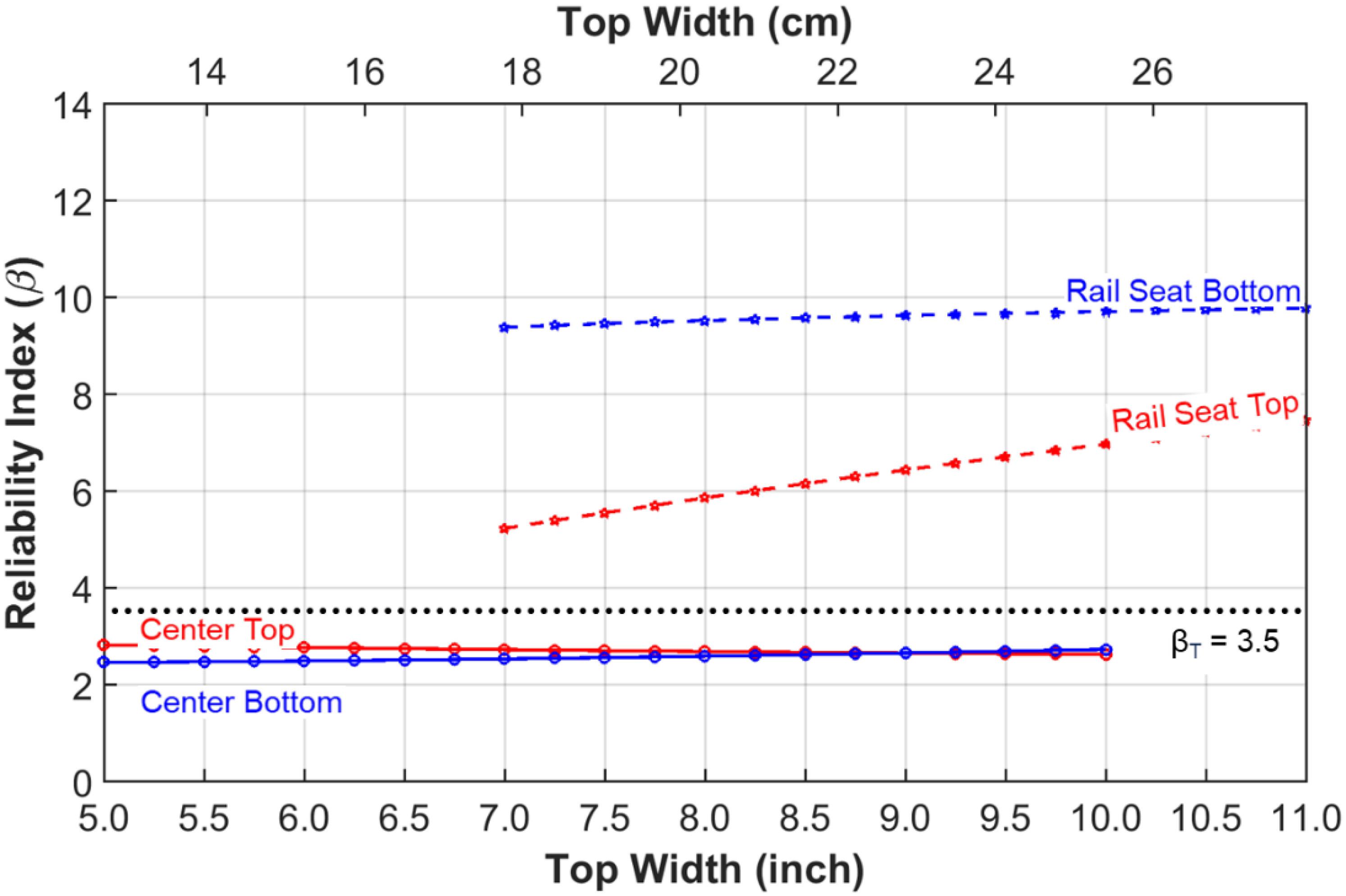
Figure 8. HAL freight center bending moment structural reliability indices (β) as a function of top width, while holding other parameters constant.
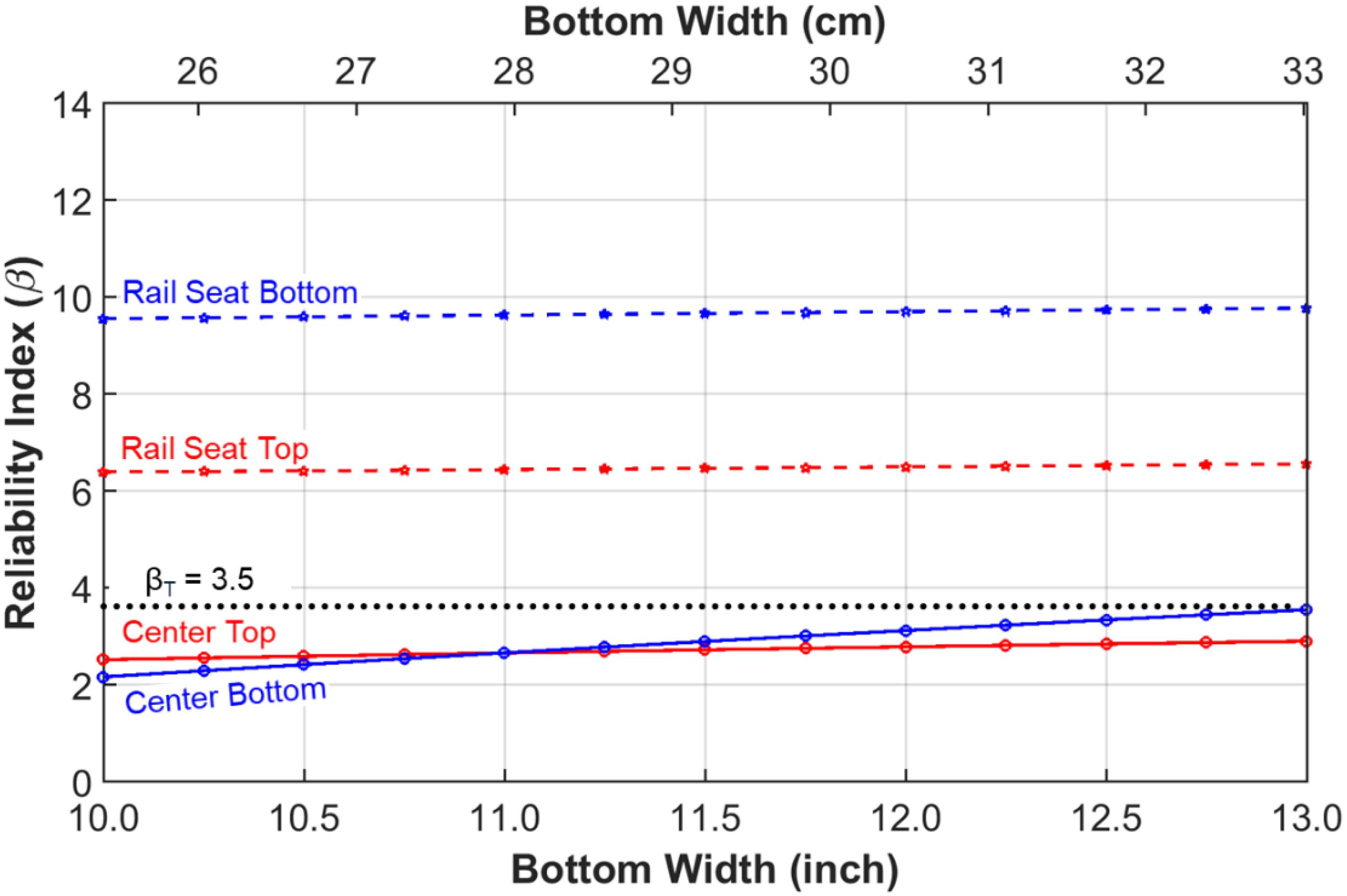
Figure 9. HAL freight center bending moment structural reliability indices (β) as a function of bottom width, while holding other parameters constant.
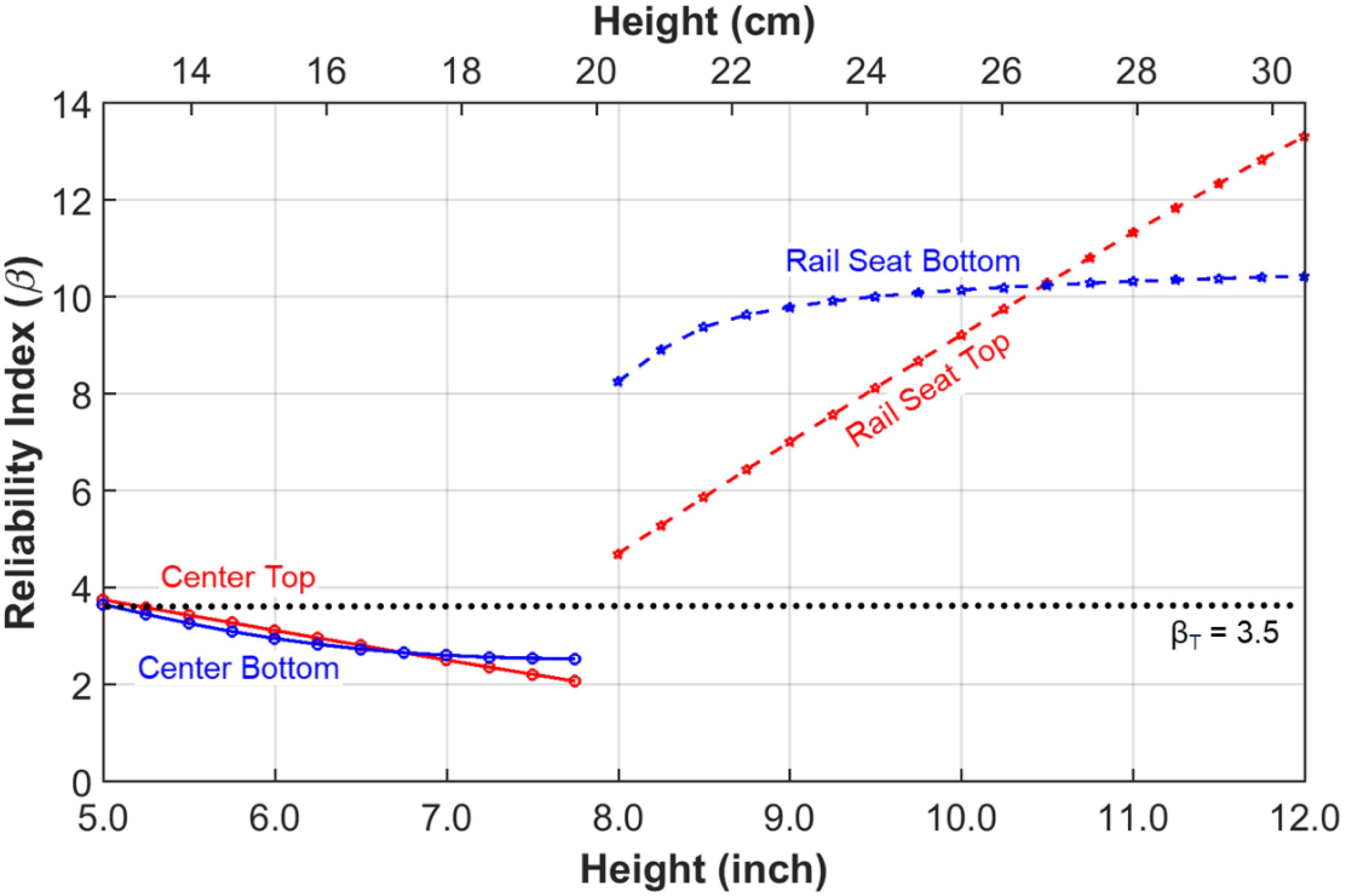
Figure 10. HAL freight center bending moment structural reliability indices (β) as a function of height, while holding other parameters constant.
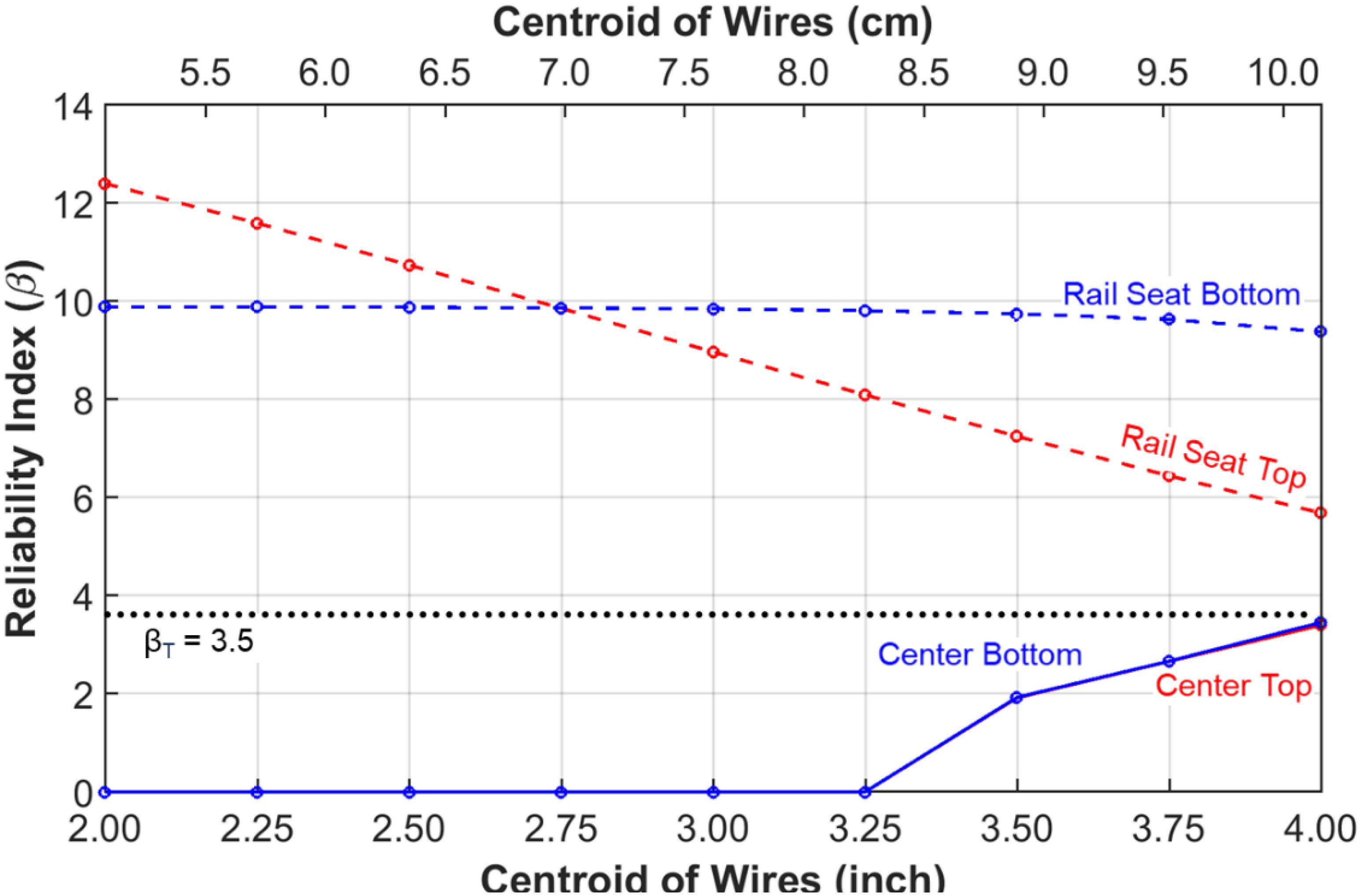
Figure 11. HAL freight center bending moment structural reliability indices (β) as a function of prestressing centroid, while holding other parameters constant.
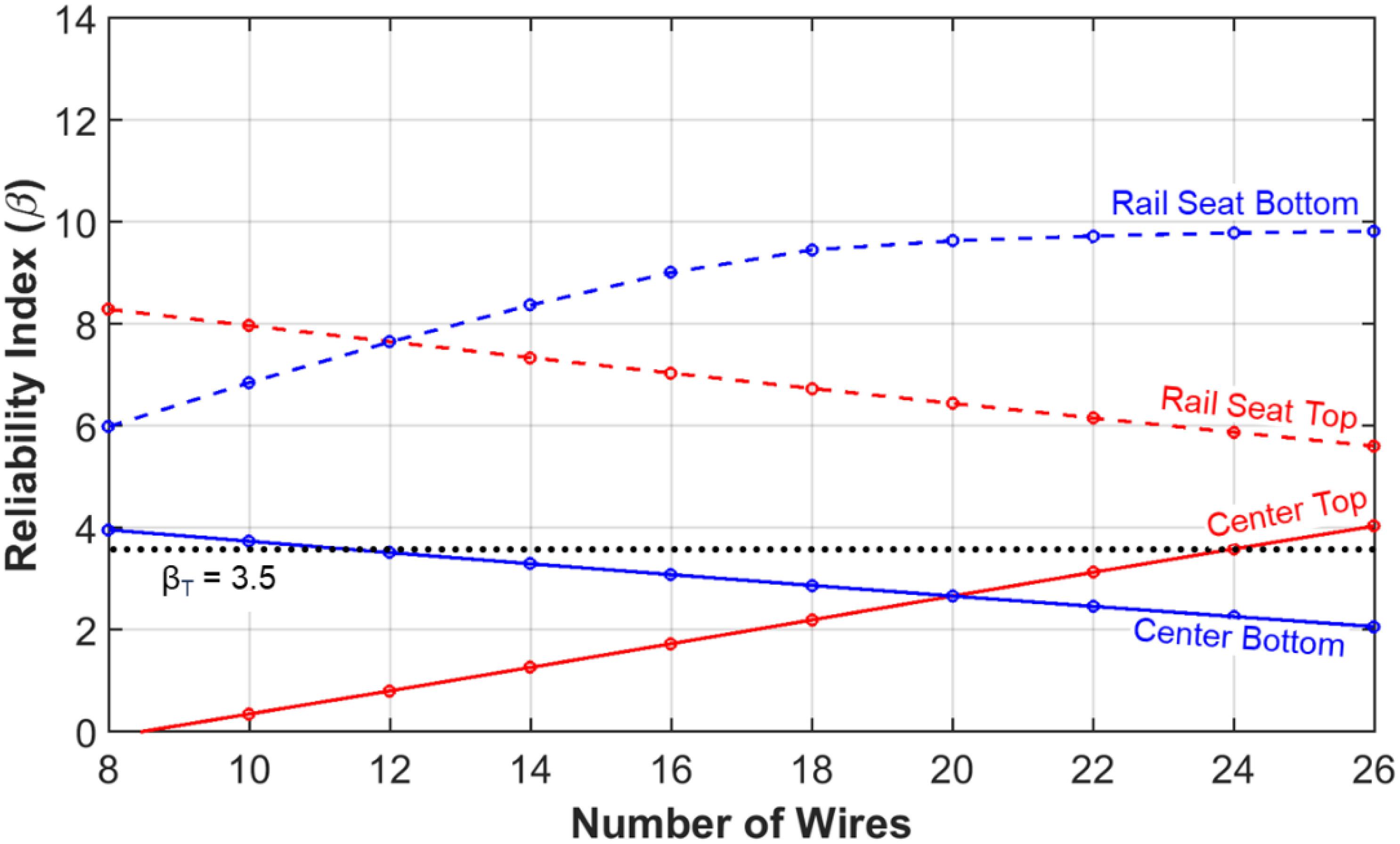
Figure 12. HAL freight center bending moment structural reliability indices (β) as a function of number of wires, while holding other parameters constant.
The above results provide insight into the sensitivity of design changes as a function of changes in deterministic input parameters. Most of the positive slopes are intuitive, given that increases in deterministic input variables increase the reliability index. For example, as the height of the sleeper changes (Figure 10) at both the center (left lines) and rail seat (right lines) distinct changes in reliability indices (β) are noted. For the sleeper center, as the height is increased, there is less conservatism in the designs due to a reversal of the eccentricity that works against the primary bending. Conversely, at the rail seats, any increase in depth of the section increases design conservatism given that the additional concrete material always improves the sleeper’s resistance to positive bending given the section centroid is always above the prestressing steel centroid.
Changes in wire centroid (Figure 11) are of particular interest, given their relation to the eccentricity of the sleeper, a primary benefit of prestressing. As the centroid increases (moves upward in the cross section) values for β decrease for the rail seat and increase for the center. The center β values are especially sensitive to centroid location, as its role in resisting negative bending at the center is the most recognizable benefit of using prestressed concrete for sleeper applications. Negative slopes are also present for rail seat negative and center positive bending as a function of increased wires (Figure 12). This is due to the eccentricity of prestress that is designed to compensate for the primary bending modes; center positive and rail seat negative. By definition, the eccentricity will only add additional tensile capacity for either positive or negative bending, thus the less prevalent bending modes are the ones that are penalized.
Using three dimensional (3D) plots it is possible to observe the effects of multiple parameters on β (Figure 13), holding all other parameters constant at the values previously discussed. Figure 13 show the effect of changes in the sleeper’s cross-sectional area and number of wires on its structural reliability index, β. Gray planes within Figure 13 represent a target β of 3.5. Results are presented for the four critical limit state functions that were previously presented; top and bottom of both center and rail seat (Figure 13).
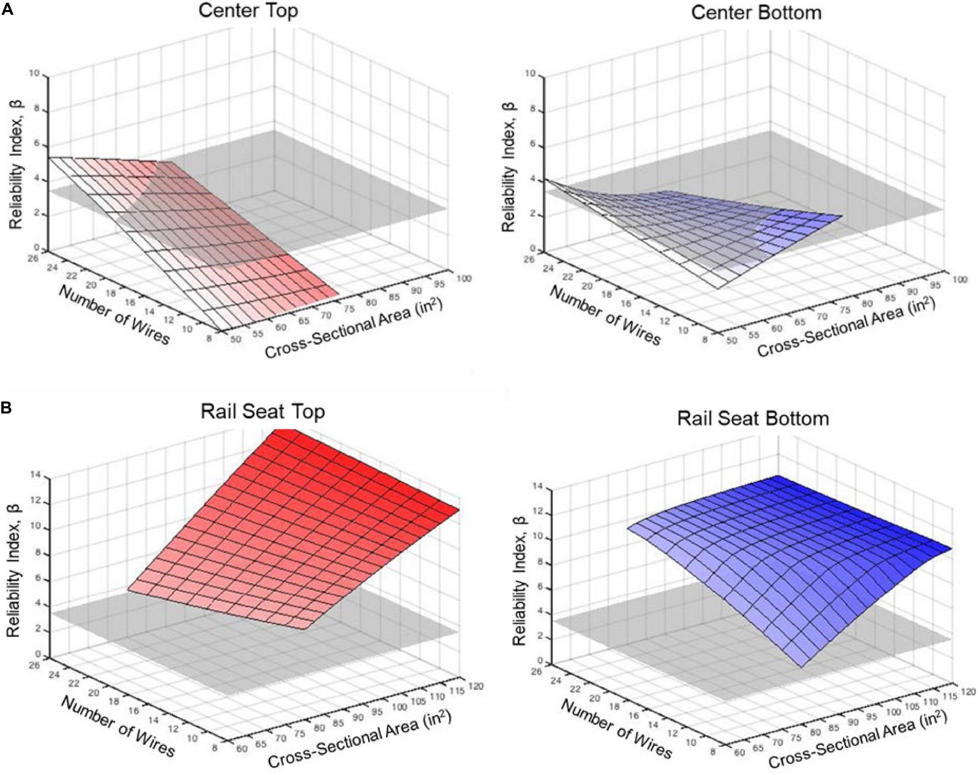
Figure 13. HAL freight center (A) and rail seat (B) bending moment structural reliability indices (β) as a function of cross-sectional area of sleeper center (A) and rail seat (B) and number of wires.
At the rail seat, the value of β increases as a function of both cross-sectional area and number of wires. Conversely, at the center section of the sleeper, β increases as a function of both cross-sectional area and number of wires. Figure 13 also indicates that there is significant residual capacity at the rail seat under the range of typical cross-sectional geometries and number of wires. The design of the center and rail seat, while commonly handled independently through sectional analysis, are linked due to geometry requirements driven by the number of strands and the location of the centroid. As such, a globally optimal sleeper design will still have one of the two critical cross-sections that has a significantly higher value for β, likely in excess of the target value of 3.5.
A probabilistic approach for the analysis and design of concrete sleepers was undertaken. The approach incorporated the use of SRA principles that were implemented using both FORM and MCS.
1. For the HAL freight sleeper, the center section was under-designed. As such, sleepers designed for HAL infrastructure could benefit from having a similar or slightly higher bending moment at the sleeper center.
2. For the HAL freight sleeper, the rail seat section could be reduced by as much as 40%.
3. Additionally, proposed designs would have fewer prestressing wires and a higher centroid of prestressing steel.
4. Application of the above recommendations would result in better balancing of the flexural capacities at the sleeper center and rail seat from a structural reliability standpoint.
The process proposed and demonstrated in this paper can be applied to ballasted track monoblock concrete sleeper designs from other locations. The analysis and design process should also consider demands that may not be representative of the exact location in which field data are collected (e.g., track transition zones, joints, etc.). This requires extrapolation of track stiffness and support conditions, a challenging undertaking that involves multiple assumptions (Quirós-Orozco, 2018).
Portions of the raw data will be made available by the authors, upon request, without undue reservation.
JE, JB, YL, AR, and MD: study conception and design, analysis and interpretation of results, and draft manuscript preparation. JE and MD: data collection. All authors reviewed the results and approved the final version of the manuscript.
AC was employed by the company Arup and YL was employed by Kiewit.
The remaining authors declare that the research was conducted in the absence of any commercial or financial relationships that could be construed as a potential conflict of interest.
ACI Committee 214 (2002). Evaluation of Strength Test Results of Concrete. Farmington Hills, MI: American Concrete Institute (ACI).
American Concrete Institute [ACI] (1997). Committee 215: Considerations For Design Of Concrete Structures Subjected To Fatigue Loading. American Concrete Institute (ACI). Farmington Hills, MI: American Concrete Institute (ACI).
American Concrete Institute [ACI] (2014). ACI 318-14 Building Code Requirements for Structural Concrete and Commentary. Farmington Hills, MI: American Concrete Institute (ACI).
American Railway Engineering and Maintenance-of-Way Association [AREMA] (2017). “Chapter 30, Part 4: concrete ties,” in Manual for Railway Engineering, (Lanham, MD: The American Railway Engineering and Maintenance-of-Way Association).
Ang, A. H. S., and Tang, W. H. (2006). Probability Concepts in Engineering: Emphasis on Applications to Civil and Environmental Engineering, 2nd Edn. New York, NY: Wiley.
Bartlett, F. M., and MacGregor, J. G. (1999). Variation of in-place concrete strength in structures. Am. Concr. Inst. Mater. J. 96, 261–270.
Bastos, J. C. (2016). Analysis of the Performance and Failure of Railroad Concrete Crossties with Various Track Support Conditions. Available at: https://www.ideals.illinois.edu/handle/2142/90659 (accessed March 10, 2017).
Bastos, J. C. (2020). Flexural Distress and Degradation Mechanisms in Pretensioned Concrete Beams and Railroad Crossties. Ph.D. Dissertation, University of Illinois at Urbana-Champaign, Champaign, IL.
Bastos, J. C., Dersch, M. S., Edwards, J. R., and Andrawes, B. O. (2017). Flexural behavior of concrete crossties under different support conditions. Am. Soc. Civ. Eng. J. Transp. Eng. 143:04017064. doi: 10.1061/JTEPBS.0000097
Bastos, J. C., Edwards, J. R., Dersch, M. S., and Andrawes, B. O. (2018). Laboratory analysis of track gauge restraining capacity of center-cracked railway concrete sleepers with various support conditions. Eng. Fail. Anal. 94, 354–363. doi: 10.1016/j.engfailanal.2018.08.018
Canga Ruiz, A. E., Edwards, J. R., Qian, Y., and Dersch, M. S. (2020). Probabilistic framework for the assessment of the flexural design of concrete sleepers. Proc. Inst. Mech. Eng. Part F J. Rail Rapid Transit. 234, 691–701. doi: 10.1177/0954409719854569
Canga Ruiz, A. E., Qian, Y., Edwards, J. R., and Dersch, M. S. (2019). Analysis of the temperature effect on concrete crosstie flexural behavior. Constr. Build. Mater. 196, 362–374. doi: 10.1016/j.conbuildmat.2018.11.065
Canga Ruiz, ÁE. (2018). Analysis of the Design of Railroad Track Superstructure Components for Rail Transit Applications. M.S. Thesis, University of Illinois at Urbana-Champaign, Champaign, IL.
Darling, D. A. (1957). The kolmogorov-smirnov, cramer-von mises tests. Ann. Math. Stat. 28, 823–838. doi: 10.1214/aoms/1177706788
Der Kiureghian, A. (2008). Analysis of structural reliability under parameter uncertainties. Probabilistic Eng. Mech. 23, 351–358. doi: 10.1016/j.probengmech.2007.10.011
Der Kiureghian, A., Haukaas, T., and Fujimura, K. (2006). Structural reliability software at the University of California. Berkeley. Struct. Saf. 28, 44–67. doi: 10.1016/j.strusafe.2005.03.002
Ditlevsen, O., and Madsen, H. O. (2007). Structural Reliability Methods. Chichester, NY: John Wiley & Sons.
Edwards, J. R. (2019). Quantification of Prestressed Concrete Railway Crosstie Flexural Response: Implications for Mechanistic Design. Ph.D. Dissertation, University of Illinois at Urbana-Champaign, Champaign, IL.
Edwards, J. R., Dersch, M. S., and Kernes, R. G. (2017a). Improved Concrete Crosstie and Fastening Systems for US High Speed Passenger Rail and Joint Corridors – Project Summary Report. Washington, DC: U.S. Department of Transportation, Federal Railroad Administration, 1.
Edwards, J. R., Gao, Z., Wolf, H. E., Dersch, M. S., and Qian, Y. (2017b). Quantification of concrete railway sleeper bending moments using surface strain gauges. Meas. J. Int. Meas. Confed. 111, 197–207. doi: 10.1016/j.measurement.2017.07.029
Edwards, J. R., Ruiz, A. E. C., Cook, A. A., Dersch, M. S., and Qian, Y. (2018). Quantifying bending moments in rail-transit concrete sleepers. Am. Soc. Civ. Eng. J. Transp. Eng. 144:04018003. doi: 10.1061/JTEPBS.0000125
Elishakoff, I. (2017). Probabilistic Methods in the Theory of Structures: Strength of Materials, Random Vibrations, and Random Buckling. Hackensack, NJ: World Scientific, doi: 10.1142/10274
Engmann, S., and Cousineau, D. (2011). Comparing distributions: the two-sample anderson-darling test as an alternative to the kolmogorov-smirnoff test. J. Appl. Quant. Methods 6:17.
European Committee for Standardization (2009). EN 13230-1:2009: Railway Applications - Track - Concrete Sleepers and Bearers - Part 1: General Requirements. Brussels: European Committee for Standardization.
European Committee for Standardization (2014). prEN 13230-6:2014 Railway Applications - Track - Concrete Sleepers and Bearers- Part 6: Design, Draft. Brussels: European Committee for Standardization.
Federal Railroad Administration [FRA] (2014). “Chapter 1 - track safety standards, classes 1 through 5,” in Track and Rail Infrastructure Integrity Compliance Manual, (Washington, DC: U.S. Department of Transportation, Federal Railroad Administration).
Frangopol, D. M., Corotis, R. B., and Rackwitz, R. (1997). Reliability and Optimization of Structural Systems, 1st Edn. Pergamon: Oxford United Kingdom.
Gao, Z., Qian, Y., Dersch, M. S., and Edwards, J. R. (2017). Compressive stress distribution in prestressed concrete and its effect on railroad crosstie design. Constr. Build. Mater. 151, 147–157. doi: 10.1016/j.conbuildmat.2017.05.186
Gao, Z., Wolf, H. E., Dersch, M. S., Qian, Y., and Edwards, J. R. (2016). “Field measurements and proposed analysis of concrete crosstie bending moments,” in Proceedings of the American Railway Engineering and Maintenance-of-Way Association Annual Conference, Orlando, FL.
Harris, D. K., Lutch, R. H., Ahlborn, T. M., and Duong, P. (2011). Optimization of a prestressed concrete railroad crosstie for heavy-haul applications. J. Transp. Eng. 137, 815–822. doi: 10.1061/(ASCE)TE.1943-5436.0000256
Heath, D., Waters, J., Shenton, M., and Sparrow, R. (1972). Design of conventional rail track FoundationS. Proc. Inst. Civ. Eng. 51, 251–267. doi: 10.1680/iicep.1972.5952
Jamshidi, A., Faghih-Roohi, S., Hajizadeh, S., Núñez, A., Babuska, R., Dollevoet, R., et al. (2017). A big data analysis approach for rail failure risk assessment. Risk Anal. 37, 1495–1507. doi: 10.1111/risa.12836
Kaewunruen, S., Li, D., Remennikov, A., and Ishida, T. (2019). “Dynamic resistance and rational design of railway prestressed concrete sleepers,” in Proceedings of the fib Symposium 2019, Krakow: fédération internationale du béton (fib), 1477–1484.
Kaewunruen, S., and Remennikov, A. M. (2009). Progressive failure of prestressed concrete sleepers under multiple high-intensity impact loads. Eng. Struct. 31, 2460–2473. doi: 10.1016/j.engstruct.2009.06.002
Kaewunruen, S., Remennikov, A. M., and Murray, M. H. (2012a). Briefing: limit states design of railway concrete sleepers. Proc. Inst. Civ. Eng. Transp. 165, 81–85. doi: 10.1680/tran.9.00050
Kaewunruen, S., Remennikov, A., and Murray, M. H. (2012b). “Development of reliability-based design for railway prestressed concrete sleepers,” in Proceedings of The 17th National Convention on Civil Engineering, Udon Thani.
Kalay, S., and Samuels, J. (2002). Reducing the stress state of the railroad. Railw. Track Struct. 13–16.
Kerr, A. D. (2003). “XI. Steel metallurgy, rail manufacturing, rail welding, and their effect on rail performance,” in Fundamentals of Railway Track Engineering, (Omaha, NE: Simmons Boardman), 337–365.
Kutner, M. H., Nachtsheim, C. J., Neter, J., and Li, W. (2005). Applied Linear Statistical Models, 5th Edn. New York, NY: McGraw-Hill Irwin.
Lee, S. (2013). Probabilistic approach on railway infrastructure stability and settlement analysis. Int. J. Railw. 6, 45–52. doi: 10.7782/IJR.2013.6.2.045
Leong, J. (2007). Development of a Limit State Design Methodology for Railway Track. Masters thesis, Queensland University of Technology, Brisbane City QLD.
Lutch, R. H. (2009). Capacity Optimization of a Prestressed Concrete Railroad Tie. Master’s Thesis, Michigan Technological University, Houghton, MI.
McHenry, M. T. (2013). Pressure Measurement at the Ballast-Tie Interface of Railroad Track Using Matrix Based Tactile Surface Sensors. Theses, University of Kentucky, Lexington, KY.
McNeely, D. J., and Lash, S. D. (1963). Tensile strength of concrete. J. American Concr. Int. 60, 751–759.
Mertol, H. C., Rizkalla, S., Zia, P., and Mirmiran, A. (2008). Characteristics of compressive stress distribution in high-strength concrete. Am. Concr. Inst. Struct. J. 105, 626–633. doi: 10.14359/19946
Murray, M. (2015). “Heavy haul sleeper design – a rational cost-saving method,” in IHHA 2015 Conference, Perth, WA.
Namura, A., Kohata, Y., and Miura, S. (2005). Study on the optimum size of railway sleeper for ballasted track. Struct. Eng. Earthq. Eng. 22, 245s–255s. doi: 10.2208/jsceseee.22.245s
Nowak, A. S., and Collins, K. R. (2013). Reliability of Structures, 2nd Edn. Boca Raton, FL: Taylor and Francis Group, CRC Press.
Nowak, A. S., and Szerszen, M. M. (2003). Calibration of design code for buildings (ACI 318): Part 1 - statistical models for resistance. American Concr. Int. Struct. J. 100, 377–382.
Prause, R. H., and Kish, A. (1978). Statistical description of service loads for concrete crosstie track. Transp. Res. Rec. 694, 30–39.
Press, W. H., Teukolsky, S. A., Vetterling, W. T., and Flannery, B. P. (2002). Numerical Recipes in C++: The Art of Scientific Computing, 2nd Edn. Cambridge: Cambridge University Press.
Quirós-Orozco, R. J. (2018). Prestressed Concrete Railway Crosstie Support Variability and its Effect on Flexural Demand. M.S. Thesis, University of Illinois at Urbana-Champaign, Champaign, IL.
Quirós-Orozco, R. J., Edwards, J. R., Qian, Y., and Dersch, M. S. (2018). Quantification of loading environment and flexural demand of prestressed concrete crossties under shared corridor operating conditions. Transp. Res. Rec. J. Transp. Res. Board. 2672, 136–145. doi: 10.1177/0361198118793500
Rakoczy, A. M., and Nowak, A. S. (2013). Resistance model of lightweight concrete members. Am. Concr. Inst. Mater. J. 110, 99–108.
Rakoczy, A. M., and Nowak, A. S. (2014). Resistance factors for lightweight concrete members. Am. Concr. Inst. Struct. J. 111, 103–111.
Remennikov, A., Murray, M. H., and Kaewunruen, S. (2007). “Conversion of AS1085.14 for prestressed concrete sleepers to limit states design format,” in AusRAIL Plus 2007, (Sydney, NSW: The Australian Railway Association (ARA)).
Remennikov, A. M., Murray, M. H., and Kaewunruen, S. (2012). Reliability-based conversion of a structural design code for railway prestressed concrete sleepers. Proc. Inst. Mech. Eng. Part F J. Rail Rapid Transit. 226, 155–173. doi: 10.1177/0954409711418754
Sadeghi, J. M. (2008). Experimental evaluation of accuracy of current practices in analysis and design of railway track sleepers. Can. J. Civ. Eng. 35, 881–893. doi: 10.1139/L08-026
Sadeghi, J. M., and Babaee, A. (2006). Structural Optimization of B70 Railway Prestressed Concrete Sleepers. Iran. J. Sci. Technol. Trans. B Eng. 30:15.
Soltanian, H., Firouzi, A., and Mohammadzadeh, S. (2018). Time dependent reliability analysis of railway sleepers subjected to corrosion. Struct. Concr. 19, 1409–1418. doi: 10.1002/suco.201800112
Standards Australia (2003). Railway Track Material, Part 14: Prestressed Concrete Sleepers. Sydney, NSW: Australia: Standards Australia Committee, CE–002.
Steenbergen, R. D. J. M., Van Gelder, P. H. A. J. M., Miraglia, S., and Vrouwenvelder, A. C. W. M. (2013). Safety, Reliability and Risk Analysis: Beyond the Horizon, 1st Edn. Boca Raton, FL: CRC Press.
Szerszen, M. M., and Nowak, A. S. (2003). Calibration of design code for buildings (ACI 318): part 2 - reliability analysis and resistance factors. Am. Concr. Inst. Struct. J. 100, 383–391. doi: 10.14359/12614
Van Dyk, B. (2014). Characterization of the Loading Environment for Shared-Use Railway Superstructure in North America. M. S. Thesis, University of Illinois at Urbana-Champaign, Champaign, IL
Van Dyk, B., Dersch, M., Edwards, J., Ruppert, C. Jr., and Barkan, C. (2014). Load characterization techniques and overview of loading environment in North America. Transp. Res. Rec. J. Transp. Res. Board. 2448, 80–86. doi: 10.3141/2448-10
Wakui, H., and Okuda, H. (1997). A study on limit state design method for prestressed concrete sleepers. Doboku Gakkai Ronbunshu 557, 35–54. doi: 10.2208/jscej.1997.557_35
Weibull, W. (1951). A statistical distribution function of wide applicability. Am. Soc. Mech. Eng. J. Appl. Mech. 18, 293–297.
Wolf, H. E. (2015). Flexural Behavior of Prestressed Concrete Monoblock Crossties. Master’s Thesis, University of Illinois at Urbana-Champaign, Department of Civil and Environmental Engineering, Urbana, IL, USA.
Wolf, H. E., Edwards, J. R., Dersch, M. S., and Barkan, C. P. L. (2015). “Flexural analysis of prestressed concrete monoblock sleepers for heavy-haul applications: methodologies and sensitivity to support conditions,” in Proceedings of the 11th International Heavy Haul Association Conference, Perth.
Wolf, H. E., Edwards, J. R., Dersch, M. S., Qian, Y., and Lange, D. A. (2016a). “Field measurement of bending moments in prestressed concrete monoblock sleepers,” in Proceedings of the World Congress on Railway Research, Milan.
Wolf, H. E., Qian, Y., Edwards, J. R., Dersch, M. S., and Lange, D. A. (2016b). Temperature-induced curl behavior of prestressed concrete and its effect on railroad crossties. Constr. Build. Mater. 115, 319–326. doi: 10.1016/j.conbuildmat.2016.04.039
You, R., Li, D., Ngamkhanong, C., Janeliukstis, R., and Kaewunruen, S. (2017). Fatigue life assessment method for prestressed concrete sleepers. Front. Built Environ. 3:68. doi: 10.3389/fbuil.2017.00068
Zanuy, C., and Albajar, L. (2018). Performance of the centre section of broad gage prestressed concrete sleepers under fatigue loading and controlled cracking. Struct. Concr. 19, 472–482. doi: 10.1002/suco.201600229
Keywords: railroad, concrete sleeper, rail seat bending moment, reliability, flexural demand, center negative bending moments
Citation: Edwards JR, Canga Ruiz AE, Bastos JC, Liang Y and Dersch MS (2020) Use of Field Flexural Demand Data for Reliability-Based Analysis and Design of Concrete Railroad Sleepers. Front. Built Environ. 6:582948. doi: 10.3389/fbuil.2020.582948
Received: 13 July 2020; Accepted: 24 September 2020;
Published: 26 October 2020.
Edited by:
Zili Li, Delft University of Technology, NetherlandsReviewed by:
Ping Wang, Southwest Jiaotong University, ChinaCopyright © 2020 Edwards, Canga Ruiz, Bastos, Liang and Dersch. This is an open-access article distributed under the terms of the Creative Commons Attribution License (CC BY). The use, distribution or reproduction in other forums is permitted, provided the original author(s) and the copyright owner(s) are credited and that the original publication in this journal is cited, in accordance with accepted academic practice. No use, distribution or reproduction is permitted which does not comply with these terms.
*Correspondence: J. Riley Edwards, amVkd2FyZDJAaWxsaW5vaXMuZWR1
Disclaimer: All claims expressed in this article are solely those of the authors and do not necessarily represent those of their affiliated organizations, or those of the publisher, the editors and the reviewers. Any product that may be evaluated in this article or claim that may be made by its manufacturer is not guaranteed or endorsed by the publisher.
Research integrity at Frontiers
Learn more about the work of our research integrity team to safeguard the quality of each article we publish.