 Mohammad Reza Chenaghlou
 Mohammad Kheirollahi1
 Karim Abedi
 Aydin Fathpour
94% of researchers rate our articles as excellent or good
Learn more about the work of our research integrity team to safeguard the quality of each article we publish.
Find out more
ORIGINAL RESEARCH article
Front. Built Environ., 25 November 2020
Sec. Structural Sensing, Control and Asset Management
Volume 6 - 2020 | https://doi.org/10.3389/fbuil.2020.561902
This article is part of the Research TopicDesign and Control of Adaptive Civil StructuresView all 13 articles
Biomimicry studies have attracted significant attention in research and practice, leading to effective engineering solutions to develop new types of structures inspired by natural systems. The objective of this study is to employ natural structures' inherent adaptivity under changing loading conditions. Three new types of compound elements are proposed that are able to improve the structure load-bearing capacity through passive inherent adaptivity. A self-centering system, inspired by the human spine, which comprises a column pre-stressed through cables, is employed as a kinematic isolator. A similar self-centering system is applied to increase the load-bearing capacity of unreinforced masonry columns. An axially loaded element, inspired by the bamboo stem, which comprises a steel core reinforced by a series of cylindrical plates that are encased in a steel tube, is employed to control the onset of instability in long-span truss structures. Application to typical frame, masonry, and truss structures is investigated through finite element analysis. Results show that the proposed compound elements are effective to increase the structure load-bearing capacity and to reduce the response under seismic excitation owning to their inherent adaptive features.
Structures capable of adapting by changing their properties or behavior in response to environmental stimuli are called adaptive structures (Wagg et al., 2008). “Structural response control” is an established field that is dedicated to the development of design methods and control systems with the objective to mitigate the structure response under external loading. Various investigations have been conducted on the application of structural control systems. Most of these systems are employed as additional components to influence the structure response. Structural control systems have been categorized as passive, semiactive, active, and hybrid. These systems can be defined as follows:
1. Passive systems reduce the structure response through employing either isolation devices (e.g., elastomeric bearings) or energy-dissipation devices (e.g., tuned mass dampers). The shared feature of these passive systems is that they do not require input energy.
2. Semiactive control systems (Symans and Constantinou, 1999, Gkatzogias and Kappos, 2016, Wang et al., 2020) employ adjustable energy-dissipation devices (e.g., magneto-rheological dampers). Sensors mounted on the structure measure acceleration and/or displacements at different locations, and based on a suitable control strategy, the semiactive device is adjusted to dissipate vibrational motion. A small amount of energy is required by the system to carry out the adjustment. Even if the adjustment mechanism fails, semiactive control systems can still function passively.
3. Active control systems (Reinhorn et al., 1993) (e.g., active mass drive or active bracing control) are capable of considerably mitigating structural vibrations using active control devices (e.g., electro-hydraulic actuators). These actuators, which are installed in the structure, provide control forces that directly reduce the structure response.
4. A hybrid control system is a combination of active and passive control strategies.
The control strategies described above are rank-ordered based on their dynamic mitigation capabilities. The reader is referred to Saaed et al. (2015), Eshaghi et al. (2016), Thieblemont et al. (2017), Yang and Yang (2018) for additional information on structural control strategies. While more effective in mitigating the effect of disturbances, active control systems are more complex and might require a large input energy. However, recent studies have shown that, through integrated structure-control design, it is possible to obtain adaptive structures that require minimum energy throughout service (Senatore et al., 2019, Senatore and Reksowardojo, 2020). Numerical simulations and experimental testing show that that, compared with a passive solution, significant (up to 50%) mass and total energy savings (embodied in the material plus operational energy for control) could be achieved through the proposed adaptive solution (Wang and Senatore, 2020).
Although significant advances have been made in the design and control of adaptive structures, reliability issues related to the structure-control system, instability, and maintenance costs might be perceived as barriers for a wide application of such active systems. For this reason, it is worth investigating new passive structural control strategies and devices. This paper investigates the use of passive control devices with inherent adaptive features that allow mitigation of the structure response with no energy input. In natural structures, adaptation is often inherently built in. “Inherent,” in its literal sense, refers to something that is “stuck” in something else so firmly that the two cannot be separated. There are many instances of inherent adaptivity in the natural world. Lindner et al. (2010) investigate the notion of inherent adaptivity in a study on trees and state that “the inherent adaptive capacity encompasses the evolutionary mechanisms and processes that permit tree species to adjust to new environmental conditions.”
An example of a biological system that has provided inspiration for this study is the human spine. The spine comprises a series of vertebrae that are held together by muscles and ligaments. The intervertebral disc, a fibro-cartilaginous joint, lies between two adjacent vertebrae to stabilize the vertebral column, and it also provides shock absorption capability. The central part of the intervertebral disc, the nucleus pulposus, has the capacity to distribute pressure evenly across the disc, preventing force concentrations (McCann et al., 2012). The ligaments are located in different parts of the spine. Anterior, posterior, and interspinous ligaments extend, respectively, along the front, behind, and between the spinous processes (Palastanga and Soames, 2011). In conjunction with the lumbar muscles, they are effective to bear loads. Figures 1A,B shows the vertebral ligaments and the components of a section of the vertebral column, respectively.
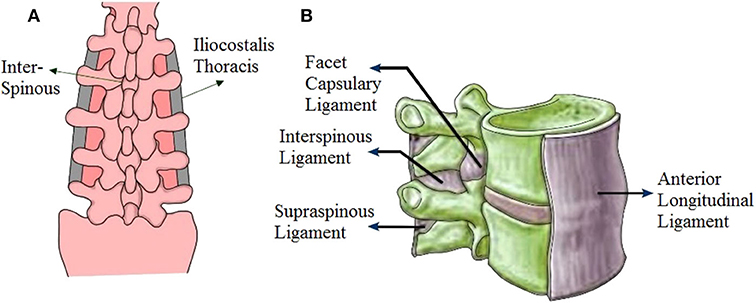
Figure 1. Components of the human spine. (A) Vertebral ligaments, (B) components of a section of the vertebral column.
Natural structures are complex systems that are made of many parts (i.e., compound) whose properties have been fine-tuned through evolution to provide inherent adaptivity to changing external actions. In most civil structures, single-function elements, such as beams and columns, are used. The development of a new element with inherent adaptivity involves the use of more complex parts. In a compound element, it is the interaction between its parts that provides adaptive load-bearing capabilities in response to external loading. Generally, compound elements can be categorized as follows:
1- Compound connection element;
2- Compound beam element;
3- Compound column element;
4- Compound beam–column element;
5- Compound wall element;
6- Compound truss element.
Examples of existing compound elements are given in Table 1. The first element is a steel accordion force limiting device (AFLD), which has been designed based on buckling restrained bracing (Poursharifi et al., 2017, Poursharifi et al., 2020). This device can be used in place of critical compressive members in spatial structures. By controlling the instability onset of critical compressive members, AFLDs increase spatial structures' load-bearing capacity.
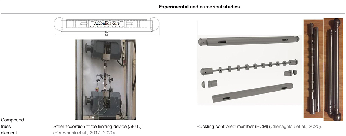
Table 1. Examples of compound elements.
The second element is a new concept named buckling-controlled member (BCM) (Chenaghlou et al., 2020). Compared to conventional truss members, the BCM offers a controlled post-buckling behavior that increases ductility and load-bearing capacity of the structure. One way to control buckling modes of compressive members is to add lateral constraints. In a BCM, this is achieved via a series of cylindrical plates (nuts) and an outer casing. Together, these components force the element to buckle through higher modes, ultimately increasing its load-carrying capacity.
In this paper, three passive compound elements with adaptive load-bearing capability are presented:
1. Compound column element inspired by the human spine;
2. Compound column element (masonry and cables) inspired by the human spine;
3. Compound truss element inspired by the bamboo stem.
Element 1 is a self-centering system inspired by the human spine, which comprises a column pre-stressed through cables. Element 1 is employed as a kinematic isolator. Element 2 is a similar self-centering system, which is applied to increase the load-bearing capacity of unreinforced masonry columns. Element 3 is an axially loaded element, inspired by the bamboo stem, which comprises a steel core reinforced by a series of cylindrical plates that are encased in a steel tube. Element 3 is employed to control the onset of instability in long-span truss structures. Application to typical frame, masonry, and truss structures is investigated through finite element analysis.
The compound column element is inspired by the human spine. It is a type of kinematic isolator, which was first proposed by Calafell et al. (2010). The compound column element is a self-centering system that comprises 4 main parts (see Figure 2): a vertical rod with rolling surfaces at both ends (similar to a lumbar vertebra), top and bottom capitals (similar to a half lumbar vertebra), circumferential cables (similar to vertebral ligaments and muscles), and top and bottom interface rubber-like material (similar to an intervertebral disc). The central rod can roll on the top and bottom surfaces of the capitals, and slippage can occur between the rolling surfaces. When the compound column is subjected to lateral loading, the tail-ends of the rolling surfaces of the central rod might come in contact with the movement restrainers of the top and bottom capitals, which function as kinematic constraints.
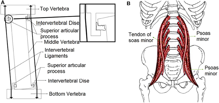
Figure 2. (A) Components of the compound column element. (B) The psoas muscle (Susan, 2015).
In the proposed column, interface rubber-like material is employed to bridge the gap between the tail-ends of the rolling surfaces with the capitals to prevent sudden impacts and also to reduce shock impact transfer to the superstructure. By pre-stressing the circumferential cables, which is similar to the contraction of the muscle surrounding the spine, the column's self-centering capability is obtained. The similarities of the proposed element to the human spine are listed in Table 2.
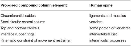
Table 2. The components of proposed compound element in comparison with human spine.
ABAQUS 6.12 has been employed to simulate the mechanical behavior of the compound column element. The components of the system, namely the top and bottom capitals, the central circular steel column, and the top and bottom interface rubber rings, have been modeled using the C3D8R element, an eight-node brick element with reduced integration. This element makes use of reduced integration algorithms to deal with shear locking issues (Simulia, 2012). Also, the T3D2 element, a three-dimensional, 2-node linear truss element, has been employed to model the circumferential cables. The mechanical properties of the top and bottom capitals and the central circular column are given in Table 3.
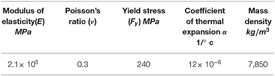
Table 3. Compound column element mechanical properties.
The Arruda and Boyce constitutive law (Arruda and Boyce, 1993) has been employed to model the behavior of the rubber rings. The material constant of the rubber material has been estimated based on guidelines recommended by the AASHTO 2000 standard (Pratt et al., 2000). The shear and bulk moduli of the rubber material with a hardness of 50 IHRD1 have been set to 620 and 15×105 kN/m2, respectively. All three translational degrees of freedom (ux, uy, uz) of all the nodes at the bottom surface have been fixed (see Figure 3). The pre-stressed cables have been selected based on specifications by ASTM Grade 270 steel strand (ASTM A 416/A 416M). The diameter of the cables and their modulus of elasticity have been set to 9.53 mm and 200 GPa, respectively. The cables are anchored between top and bottom capitals. The cables have been pre-stressed using an initial tensile force of 10 kN. The interactions of the rolling surface of the central steel column with the top and bottom capitals have been accounted for using hard contact elements. Moreover, the interaction between the surfaces of the capitals and the column has been taken into account using kinematic contact elements. Also, the friction coefficient between the rolling surfaces and the capitals has been considered sufficiently high in order to avoid sliding. The other surfaces have been modeled with frictionless elements.
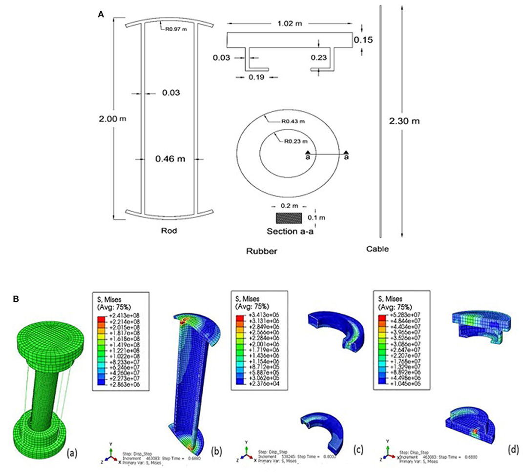
Figure 3. (A) Components of the compound column element, (B) deformed shape and Von Mises stress contours.
Figure 3A shows the components of the compound column element. Two models are set up to investigate
- The behavior of a single compound column element
- Application of the compound column element as a kinematic isolator in a moment resisting frame.
Gravity load has been applied to the top surface of the column. A target displacement of ±0.25 m has been defined. The force-displacement responses of the model have been determined in the following four cases:
1. With no pre-stressed cables as well as no top and bottom interface rubber rings.
2. Adding pre-stressed cables.
3. Adding top and bottom interface rubber rings.
4. Adding both pre-stressed cables as well as top and bottom interface rubber rings.
With the addition of the cables and the interface rubber rings, the capacity of the column progressively increases as seen from Figure 4A. The inclusion of these elements has improved the performance of the column and eliminated residual displacements. The deformed shape and von Mises stress contours for case 4 are shown in Figures 3B–D.
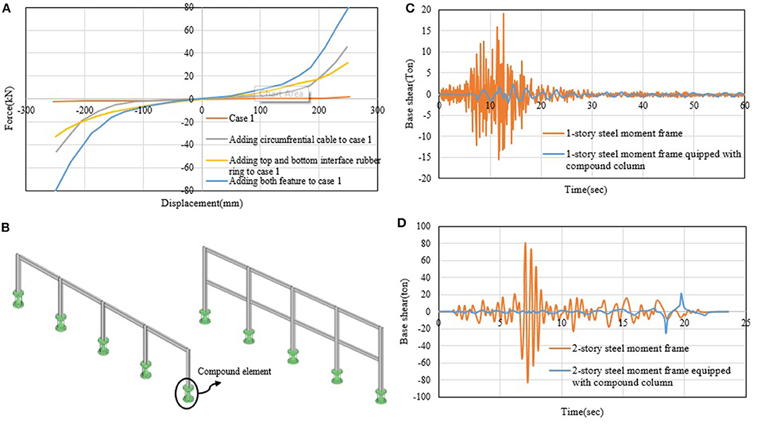
Figure 4. (A) Force-displacement response of the compound column element, (B) One- and two-story steel frames equipped with compound column element (kinematic isolator); Base shear response for 1-story (C) and 2-story (D) steel frame subjected to Montebello Northridge, 1994 ground motion.
Application of the compound column element to mitigate the structure response under seismic excitation has been studied. The compound element is employed as a kinematic isolator applied to the base of the columns of a moment resisting frame.
The behavior of the moment resisting frame is analyzed with/without the compound element. Two steel moment resisting frames (a one- and a two-story frame) are considered. Each of the two frames has four bays. As shown in Figure 4B, the span of the bays and the height of the stories are 5 and 3.2 m, respectively. The magnitudes of the dead and live loads have been set to 650 and 200 kg/m2, respectively. The seismic mass of the frame consists of the dead load in addition to 20% of the live load. Plastic hinges have been used to model the non-linear behavior of the structure. Plastic hinges have been used in the beams and columns based on guidelines by the ASCE 41-13 (ASCE, 2013) standard. For columns, the standard recommends the use of plastic hinges that are based on the interaction between axial forces and bending moments. The standard also recommends using bending moment-based plastic hinges for the beams. Non-linear time history analysis has been performed under 1994 Northridge ground motion. In the analysis, the Wilson-θ time integration method has been employed, whose stability and accuracy are determined by the parameter θ. This parameter and the damping ratio have been set to 1.4% and 5%, respectively. SAP2000 (Sap, 2016) has been used to carry out the non-linear time-history analysis. After evaluating the behavior of the steel frames, the compound element has been incorporated as a kinematic isolator placed at the base of the frame columns. Link elements have been used to model the column. The results of the analyses are shown in Figures 4C,D. The total base shear of the structure equipped with the compound element is significantly reduced (up to 87.26 and 95.86%, respectively) with respect to the original structure. This shows that the compound column element is an effective kinematic isolator, which is able to reduce the seismic response of frame structures subjected to seismic excitation.
A similar self-centering system to that described in section Compound Truss Element is applied to improve load-bearing capability of masonry columns. In this compound element, cables can be thought of as the ligaments, the masonry column as the vertebral column, and top and bottom concrete capitals as the vertebrae of the human spine (see Figure 5). The behavior of this element has been analyzed through finite element modeling in ABAQUS 6.12 (Simulia, 2012). The results have been compared to the original masonry pier that is not equipped with pre-stressed cables. To model unreinforced masonry structures, different numerical approaches are employed. The following section gives details of the modeling procedure.
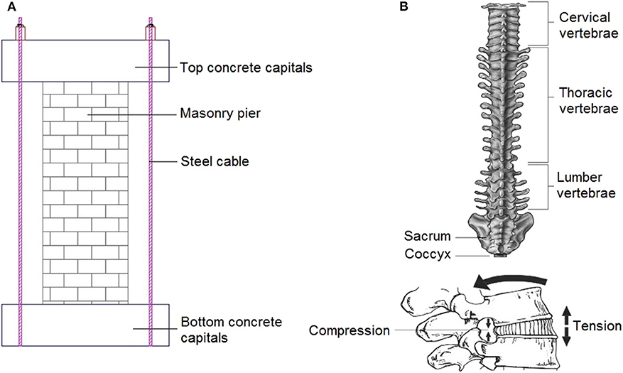
Figure 5. (A) Compound column element (masonry and cables), (B) human spine (Susan, 2015).
Masonry is one of the oldest materials used in construction. New methods of analyzing masonry structures have been the focus of recent studies (Lotfi and Shing, 1991, Lourenço and Rots, 1997, Shing et al., 1992, Berto et al., 2004, Milani, 2008, Milani, 2011a, Milani, 2011b, Stavridis and Shing, 2010, Minaie, 2010). The finite element method (FEM) is a robust and powerful numerical method for the modeling of masonry structures (Bolhassani et al., 2015). FEM approaches for modeling masonry structures are classified into two categories: heterogeneous and homogeneous. In the heterogeneous approach, although collectively assumed as a single material, the mortar and the masonry units are considered as separate entities. Although the heterogonous method of modeling masonry materials is generally more accurate compared to the homogenous approach, it is far more time-consuming. Therefore, modeling masonry structures using either method depends on the level of desired accuracy.
Some of the procedures that may be adopted to model masonry structures are given in the flowchart of Figure 6. Among the most commonly used modeling procedures are
• The macro-modeling procedure, in which masonry units, mortar, and unit–mortar interfaces are merged in a homogeneous continuum.
• The detailed micro-modeling procedure, in which the masonry units and mortar joints—i.e., the mortar-filled intervals separating the bricks—are modeled using continuum elements. However, discontinuous elements are used for modeling unit–mortar interfaces.
• The simplified micro-modeling procedure, in which expanded units are represented by continuum elements, whereas the behavior of the mortar joints and unit–mortar interface is lumped in discontinuous elements (Laurenco et al., 1995).
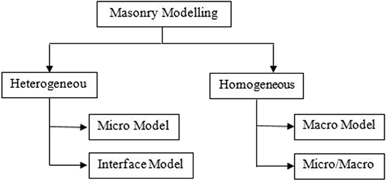
Figure 6. Modeling strategies for masonry structures (Bolhassani et al., 2015).
According to the abovementioned methods, in this study, the simplified micro-modeling method has been adopted.
The following models have been studied:
1- A masonry pier;
2- A masonry pier equipped with pre-stressed cables.
Non-linear static analysis has been performed on each model. The dimensions of the pier are 30× 30× 100 cm. The brick sizes are 20× 10× 5 cm and 10× 10× 5 cm. The cables have a diameter of 10 mm. Material properties of the bricks, concrete capitals, and cables are given in Table 4. As mentioned before, the simplified micro-modeling technique has been used for the model. Also, concrete damage plasticity (CDP) has been employed to model the non-linear behavior of the masonry. Although this criterion is primarily used for isotropic brittle materials like concrete, it has also been extensively used for anisotropic materials such as masonry. The CDP model can take into account compressive and tensile strength with different damage parameters. In this model, tension and compression stress states are defined by the tensile damage index (dt) and compressive damage index (dc), respectively.
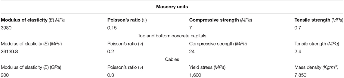
Table 4. Material properties of bricks, concrete capitals, and cables.
Material behavior in tension is linear up to the yield stress σt0. Above this value, cracks propagate, which is represented by a sudden drop of the stress–strain curve. The decay rate in the stress–strain curve is controlled by dt (see Figure 7A). In compression, the behavior is linear until the yield stress σc0. Then, hardening occurs before compressive crushing initiates. Above the peak stress σcu, the stress–strain curve drops due to softening. The rate of decay in the compressive stress–strain curve is controlled by dc (see Figure 7B).
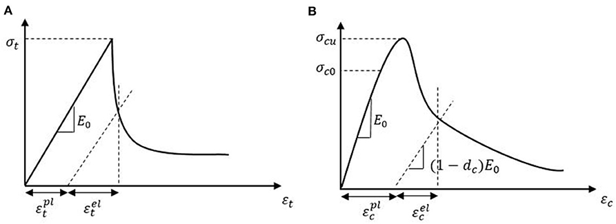
Figure 7. Tension and compression behavior of masonry material modeled using the CDP model (Simulia, 2012). (A) Tensile behavior, (B) Compression behavior.
The damage parameters in tension (dt) and compression (dc) are defined by the following relationships:
wherein σt and σc are the tensile and compressive stresses; E0 is the initial elastic modulus; εt and εc are, respectively, the total strain in tension and compression; and and are, respectively, the plastic strains in tension and compression. A summary of concrete damage parameters used in the non-linear analysis is given in Table 5.
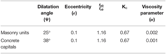
Table 5. Concrete damage plasticity parameters for masonry units and concrete.
The interaction between two brick units has been modeled by taking into account cohesion and friction. A sensitivity analysis has been carried out to achieve appropriate mesh sizing. Mortar material properties have been used in the simplified micro-modeling procedure. The model proposed by Mehrabi and Shing (1997) has been used to assign frictional, cohesive, and post-failure characteristics. A small non-zero value (≅ 0.001) has been used for the friction failure coefficient (Mehrabi and Shing, 1997). Also, the mortar tensile and shear stiffness have been determined using Equations (4) and (5), proposed by Furukawa et al. (2012):
wherein is the normal or tensile stiffness between the mortar layers, is the shear stiffness between the mortar layers, lA and lB are the distances from the surface of the masonry unit to its center, and tM is the mortar layer thickness. EA, EB, and EM are the elastic moduli of upper and lower masonry units and the mortar, respectively. υA, υB, and υM are the Poisson ratios of upper and lower masonry units and the mortar, respectively. Table 6 gives cohesion and fiction material properties adopted in the model.
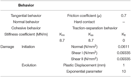
Table 6. Cohesive and frictional behavior of the numerical model.
The base of the masonry columns is fully fixed. A vertical gravity load has been applied to the top of the column and kept constant throughout the displacement-control analysis. A horizontal displacement of 20 cm has been applied to the top of the column. Von Mises stress contours are shown in Figure 8A. The masonry pier collapses in the absence of cables, while adding the cables increases significantly the load-bearing capacity. Also, the action of cables prevents cracks from propagating into the pier. Comparing the base shear-displacement curves in the two states shows that the pre-stressed cables have significantly increased the capacity of pier (see Figure 8B).
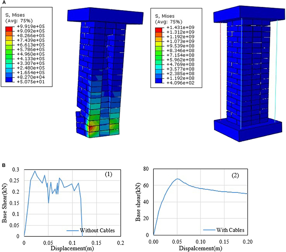
Figure 8. (A) Von- Mises stress contours of the masonry pier. (B) Base shear-displacement curves of masonry pier (1) without cables, (2) with cables.
This compound element is inspired by the morphology of the bamboo stem. The proposed element comprises a steel core, adjustable cylindrical plates (nuts), and a steel casing. The similarity of the proposed element with the bamboo stems is illustrated in Figure 9. When the steel core alone is under the action of the compressive load P, it buckles easily. Addition of the cylindrical plates (i.e., nuts) between the core and the casing is effective to postpone the onset of buckling of the steel core (Chenaghlou et al., 2020). The cylindrical plates (nuts) are fixed to the steel core similar to how a nut is fixed to a screw. The cylindrical nuts and the steel core are placed inside the steel casing. Compressive load is first applied to the steel core, and after it buckles, the load is transferred to the steel casing. There is a 1-mm gap between the steel casing and the steel core. In other words, there is no contact between the steel core and the steel casing prior to buckling. The gap allows the steel core to go through different buckling modes before making contact with the casing. This way, the member reacts to compressive loads in two stages. In the first stage, the after the steel core reaches its maximum capacity, it buckles. In the second stage, the two components (i.e., the core and the casing) come into contact, and the casing is only responsible for controlling post-buckling effects.
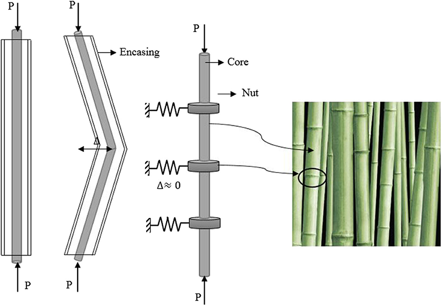
Figure 9. The mechanism of the proposed compound element (Chenaghlou et al., 2020).
Application of this compound element has been investigated for long-span spatial structures, such as roof systems with a large cover. These structures tend to be brittle and go through progressive collapse when a number critical compressive members buckle (Schmidt et al., 1980, Schmidt et al., 1982). Several techniques have been developed to delay the onset of brittle collapse for these structures. One of these techniques is the application of a force limiting device (FLD) in the critical compressive members. The compound truss element presented in this section is a new FLD that can be employed to replace critical compressive members in spatial structures. This element is illustrated in Figure 10A. A double-layer flat roof is selected to investigate the efficacy of such compound element (see Figure 10B).
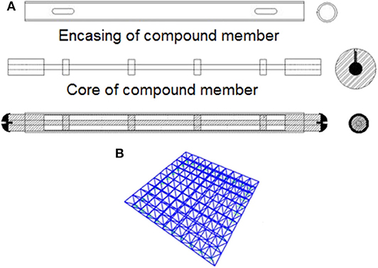
Figure 10. (A) Compound truss element, (B) Double-layer flat roof.
The structure is designed to take dead and snow loads, which have been applied following the Iranian national code of buildings (Housing and Development, 2014). Non-linear analyses have been carried out using ABAQUS. Geometric and material non-linearity has been taken into account. Mechanical properties and cross-section properties of the structural elements are given in Tables 7, 8.
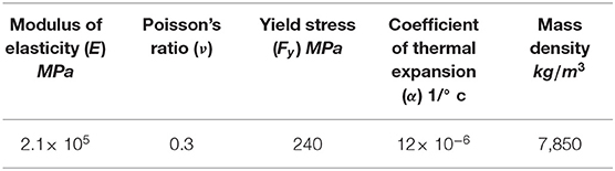
Table 7. Material mechanical properties.
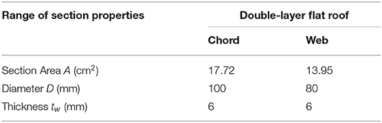
Table 8. Spatial structure element cross-section section properties.
The compound element is first studied in isolation under compressive loading. A slenderness ratio of λ =85 and an initial geometrical imperfection of 0.001 L applied at midlength have been considered. The axial displacement response of the encasing element (without nuts) is shown in Figure 11A and that of the compound element is shown in Figure 11B.
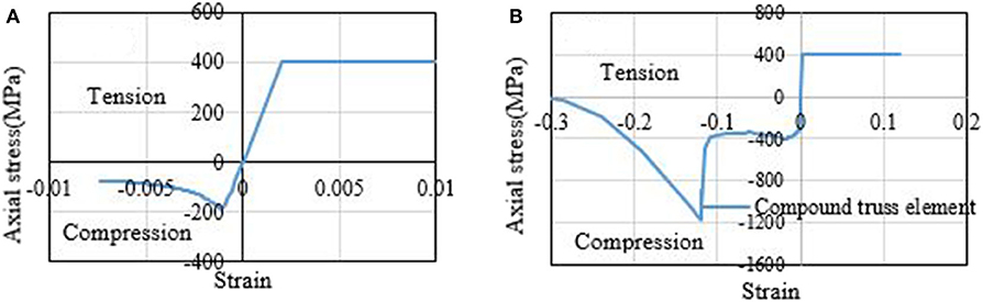
Figure 11. Axial displacement response of (A) encasing member with a slenderness ratio of λ =85 and (B) compound truss element.
The obtained results show that, when the encasing reaches its critical capacity under compressive loading, it buckles and undergoes a sudden strength degradation. However, after the addition of the steel core, the brittle behavior of the casing changes to a ductile one, which persists until a strain of ~-0.1. At this point, the core and the casing come in contact, resulting in a sudden surge in strength of the member. After reaching a maximum stress of ~1,200 MPa, the member goes through failure
The effect of using such a compound element in spatial structures has been evaluated. The location of buckled members (see Figure 12A) and the collapse behavior of the structure have been determined using non-linear static analysis. Then, the proposed compound element has been used in place of the buckled members. Another non-linear static analysis has been carried out replacing the critical compressive elements with the proposed compound element. Figure 12B shows the force-displacement response of the spatial structure with and without compound elements. The effect of the compound elements has changed the structure behavior from brittle to ductile ultimately delaying significantly the onset of collapse. Simulation results indicate that application of the compound truss element improves energy absorption, ductility, stiffness, and capacity of the double-layer flat roof by up to 58, 64, 17, and 53%, respectively. Given that the proposed compound truss element is used in place of only a few critical members, the structure mass increases by 9.755%, which is not a significant penalty.
Figure 12. (A) Location of critical compressive elements, (B) Force-displacement response with and without compound truss elements.
This study has taken inspiration from natural structures inherent adaptive capabilities. Three compound elements that improve structures' load-bearing capacity through passive inherent adaptivity have been proposed in this paper. These elements are (1) a self-centering column inspired by the human spine, (2) a self-centering unreinforced masonry pier with cables also inspired by the human spine, and (3) an FLD (compound truss member) inspired by the bamboo stem.
The behavior of each compound element and its efficacy when employed as load-bearing member has been investigated through FEM. Based on the obtained results, the following conclusions can be drawn:
• Using the compound column element as a kinematic isolator is effective to mitigate the response of frame structures subjected to ground motion. Simulations on a one- and two-story moment resisting frames under seismic excitation have shown that the base shear decreases by 87.26 and 95.86%, respectively.
• The self-centering property of the compound masonry column element postpones collapse onset and prevents crack propagation. The effect of pre-stressed cables significantly increases the masonry column load-bearing capacity, which becomes twice as ductile compared to the masonry column that is not equipped with pre-stressed cables.
• Replacing critical compression members with the compound truss element is effective to increase ductility of long-span spatial structures as well as energy absorption, stiffness, and load-bearing capacity.
The raw data supporting the conclusions of this article will be made available by the authors, without undue reservation.
The main objective of this paper is to show how the inspiration from the nature has influenced the designing of structures and discusses how the nature-inspired idea could convert into a new language for the future structural design industry. Also, the new concept for inherent adaptive control of structures and compound element based on natural creatures inspired from nature is introduced and compound element.
All authors listed have made a substantial, direct and intellectual contribution to the work, and approved it for publication.
The authors declare that the research was conducted in the absence of any commercial or financial relationships that could be construed as a potential conflict of interest.
The authors gratefully acknowledge Maryam Chenaghlou, MD, cardiologist, fellowship of heart failure and transplantation at the Rajaie cardiovascular medical and research center, for her assistance.
1. ^International Rubber Hardness Degrees (ASTM D1415).
Arruda, E. M., and Boyce, M. C. (1993). A three-dimensional constitutive model for the large stretch behavior of rubber elastic materials. J. Mech. Phys. Solids 41, 389–412. doi: 10.1016/0022-5096(93)90013-6
ASCE (2013). ASCE/SEI 41-13: Seismic Evaluation and Retrofit of Existing Buildings. Reston, VA: American Society of Civil Engineers.
Berto, L., Saetta, A., Scotta, R., and Vitaliani, R. (2004). Shear behaviour of masonry panel: parametric FE analyses. Int. J. Solids Struct. 41, 4383–4405. doi: 10.1016/j.ijsolstr.2004.02.046
Bolhassani, M., Hamid, A. A., Lau, A. C., and Moon, F. (2015). Simplified micro modeling of partially grouted masonry assemblages. Constr. Build. Mater. 83, 159–173. doi: 10.1016/j.conbuildmat.2015.03.021
Calafell, R. L., Roschke, P. N., and Juan, C. (2010). Optimized friction pendulum and precast-prestressed pile to base-isolate a Chilean masonry house. Bull. Earthquake Eng. 8, 1019–1036. doi: 10.1007/s10518-009-9163-0
Chenaghlou, M R., Kheirollahi, M., and Abedi, K. (2020). Patent No. E04C 3/00;E04B 1/00, Patent and Trademark Office. Tabriz-Iran patent application.
Eshaghi, M., Sedaghati, R., and Rakheja, S. (2016). Dynamic characteristics and control of magnetorheological/electrorheological sandwich structures: a state-of-the-art review. J. Intell. Mater. Syst. Struct. 27, 2003–2037. doi: 10.1177/1045389X15620041
Furukawa, A., Kiyono, J., and Toki, K. (2012). Numerical simulation of the failure propagation of masonry buildings during an earthquake. J. Nat. Disaster Sci. 33, 11–36. doi: 10.2328/jnds.33.11
Gkatzogias, K. I., and Kappos, A. J. (2016). Semi-active control systems in bridge engineering: a review of the current state of practice. Struct. Eng. Int. 26, 290–300. doi: 10.2749/101686616X14555429844040
Housing, M. O., and Development, U. (2014). Iranian National Building Code (Part 6). 3rd ed. Ministry of Housing and Urban Development, Tehran, Iran.
Laurenco, P., Rots, J. G., and Blaauwendraad, J. (1995). Two approaches for the analysis of masonry structures: micro and macro-modeling. HERON 40:1995.
Lindner, M., Maroschek, M., Netherer, S., Kremer, A., Barbati, A., Garcia-Gonzalo, J., et al. (2010). Climate change impacts, adaptive capacity, and vulnerability of European forest ecosystems. For. Ecol. Manage 259, 698–709. doi: 10.1016/j.foreco.2009.09.023
Lotfi, H., and Shing, P. (1991). An appraisal of smeared crack models for masonry shear wall analysis. Comput. Struct. 41, 413–425. doi: 10.1016/0045-7949(91)90134-8
Lourenço, P. B., and Rots, J. G. (1997). Multisurface interface model for analysis of masonry structures. J. Eng. Mech. 123, 660–668. doi: 10.1061/(ASCE)0733-9399(1997)123:7(660)
McCann, M. R., Tamplin, O. J., Rossant, J.„ Séguin, C. A. (2012). Tracing notochord-derived cells using a Noto-cre mouse: implications for intervertebral disc development. Dis. Model. Mech. 5, 73–82. doi: 10.1242/dmm.008128
Mehrabi, A. B., and Shing, P. B. (1997). Finite element modeling of masonry-infilled RC frames. J. Struct. Eng. 123, 604–613. doi: 10.1061/(ASCE)0733-9445(1997)123:5(604)
Milani, G. (2008). 3D upper bound limit analysis of multi-leaf masonry walls. Int. J. Mech. Sci. 50, 817–836. doi: 10.1016/j.ijmecsci.2007.11.003
Milani, G. (2011a). Simple homogenization model for the non-linear analysis of in-plane loaded masonry walls. Comput. Struct. 89, 1586–1601. doi: 10.1016/j.compstruc.2011.05.004
Milani, G. (2011b). Simple lower bound limit analysis homogenization model for in-and out-of-plane loaded masonry walls. Const. Build. Mater. 25, 4426–4443. doi: 10.1016/j.conbuildmat.2011.01.012
Minaie, E. (2010). Behavior and vulnerability of reinforced masonry shear walls (Ph.D. thesis). Drexel University.
Palastanga, N., and Soames, R. (2011). Anatomy and Human Movement, Structure and Function With PAGEBURST Access, 6: Anatomy and Human Movement. London: Elsevier Health Sciences.
Poursharifi, M., Abedi, K., Chenaghlou, M., and Fleischman, R. B. (2020). Introducing a new all steel accordion force limiting device for space structures. Struct. Eng. Mech. 74, 69–82. doi: 10.12989/sem.2020.74.1.069
Poursharifi, M., Abedi, K., and Chenaghloua, M. (2017). 05.32: Experimental and numerical study on the collapse behavior of an all-steel accordion force limiting device. ce/papers 1, 1315–1324. doi: 10.1002/cepa.173
Pratt, R. I., Roush, N. H., Ruff, W. T., Schneider, M. M. E. (2000). American Association of State Highway and Transportation Officials.
Reinhorn, A., Soong, T., Riley, M., Lin, R., Aizawa, S., and Higashino, M. (1993). Full-scale implementation of active control. II: installation and performance. J. Struct. Eng. 119, 1935–1960. doi: 10.1061/(ASCE)0733-9445(1993)119:6(1935)
Saaed, T. E., Nikolakopoulos, G., Jonasson, J.-E., and Hedlund, H. (2015). A state-of-the-art review of structural control systems. J. Vibrat. Control 21, 919–937. doi: 10.1177/1077546313478294
Sap, C. (2016). Integrated Finite Element Analysis and Design of Structures. Version 18.0. Berkeley, CA: Computers and Structures Inc.
Schmidt, L., Cogan, K., Morgan, P., and Omeagher, A. (1980). Ultimate load behaviour of a full scale space truss. Proc. Institution Civil Eng. 69, 97–109. doi: 10.1680/iicep.1980.2489
Schmidt, L. C., Morgan, P., and Hanaor, A. (1982). Ultimate load testing of space trusses. J. Struct. Division 108, 1324–1335. doi: 10.1061/(ASCE)0733-9445(1983)109:5(1334.2)
Senatore, G., Duffour, P., and Winslow, P. (2019). Synthesis of minimum energy adaptive structures. Struct. Multidisciplinary Optimization 60, 849–877. doi: 10.1007/s00158-019-02224-8
Senatore, G., and Reksowardojo, A. (2020). Force and shape control strategies for minimum energy adaptive structures. Front. Built Environ. 6:105. doi: 10.3389/fbuil.2020.00105
Shing, P., Lofti, H., Barzegarmehrabi, A. and Bunner, J. (1992). “Finite element analysis of shear resistance of masonry wall panels with and without confining frames,” in Proceedings of the 10th World Conference on Earthquake Engineering. Netherlands: AA Balkema Rotterdam, 2581-2586.
Stavridis, A., and Shing, P. (2010). Finite-element modeling of nonlinear behavior of masonry-infilled RC frames. J. Struct. Eng. 136, 285–296. doi: 10.1061/(ASCE)ST.1943-541X.116
Symans, M. D., and Constantinou, M. C. (1999). Semi-active control systems for seismic protection of structures: a state-of-the-art review. Eng. Struct. 21, 469–487. doi: 10.1016/S0141-0296(97)00225-3
Thieblemont, H., Haghighat, F., Ooka, R., and Moreau, A. (2017). Predictive control strategies based on weather forecast in buildings with energy storage system: a review of the state-of-the art. Energy Buildings, 153, 485–500. doi: 10.1016/j.enbuild.2017.08.010
Wagg, D., Bond, I., Weaver, P., and Friswell, M. (2008). Adaptive Structures: Engineering Applications. Chichester: John Wiley & Sons. doi: 10.1002/9780470512067
Wang, Q., Senatore, G., Jansen, K., Habraken, A., and Teuffel, P. (2020). Design and characterization of variable stiffness structural joints. Mater. Des. 187:108353. doi: 10.1016/j.matdes.2019.108353
Wang, Y., and Senatore, G. (2020). Minimum energy adaptive structures–All-In-One problem formulation. Comput. Struct. 236:106266. doi: 10.1016/j.compstruc.2020.106266
Keywords: inherent adaptivity, compound element, self-centering system, masonry columns, truss structures, seismic excitation
Citation: Chenaghlou MR, Kheirollahi M, Abedi K, Akbari A and Fathpour A (2020) Inherent Adaptive Structures Using Nature-Inspired Compound Elements. Front. Built Environ. 6:561902. doi: 10.3389/fbuil.2020.561902
Received: 14 May 2020; Accepted: 08 October 2020;
Published: 25 November 2020.
Edited by:
Gennaro Senatore, École Polytechnique Fédérale de Lausanne, SwitzerlandReviewed by:
Julio Alfonso Ramirez, Purdue University, United StatesCopyright © 2020 Chenaghlou, Kheirollahi, Abedi, Akbari and Fathpour. This is an open-access article distributed under the terms of the Creative Commons Attribution License (CC BY). The use, distribution or reproduction in other forums is permitted, provided the original author(s) and the copyright owner(s) are credited and that the original publication in this journal is cited, in accordance with accepted academic practice. No use, distribution or reproduction is permitted which does not comply with these terms.
*Correspondence: Mohammad Reza Chenaghlou, bXJjaGVuYWdobG91QHN1dC5hYy5pcg==
Disclaimer: All claims expressed in this article are solely those of the authors and do not necessarily represent those of their affiliated organizations, or those of the publisher, the editors and the reviewers. Any product that may be evaluated in this article or claim that may be made by its manufacturer is not guaranteed or endorsed by the publisher.
Research integrity at Frontiers
Learn more about the work of our research integrity team to safeguard the quality of each article we publish.