 Adam Coles1
 Bruno Albuquerque de Castro1,2
 Christos Andreades3
 Fabricio Guimarães Baptista2Michele Meo3
 Francesco Ciampa1*
- 1Department of Mechanical Engineering Sciences, University of Surrey, Guildford, United Kingdom
- 2Department of Electrical Engineering, School of Engineering, São Paulo State University (UNESP), Bauru, Brazil
- 3Department of Mechanical Engineering, University of Bath, Bath, United Kingdom
Time reversal is a powerful imaging processing technique that focuses waves at their original source using a single receiver transducer when diffusive wave field conditions are met. This has been successfully proved on various engineering components and materials using elastic waves with surface bonded transducers. This paper investigates the performance of time reversal for the localization of impact sources on fiber reinforced plastic composite structures with embedded piezoelectric sensors. A topologic approach, here named as minimum average method, is proposed to enhance the accuracy of time reversal in retrieving the impact location. Experimental tests were carried out to validate the robustness and reliability of time reversal against traditional topological approaches by altering impulsive responses contained in the baseline signals. Impact localization results revealed that time reversal and the new topological approach provided high accuracy in identifying the impact location, particularly in the presence of double impacts and material damage, which were not accounted during the initial training process. Results indicate that time reversal with embedded transducers has potential to be effective in real operating conditions, where alterations of acoustic emission responses in the baseline signals are less predictable.
Introduction
Fiber reinforced plastic (FRP) composite materials are becoming increasingly popular, particularly in the aerospace field, due to their higher mechanical benefits over metals such as low weight and high stiffness and strength (Chandrashekhar and Ganguli, 2016; Baccar and Söffker, 2017; Castro et al., 2019). However, composite components can often demonstrate fragility toward low-velocity impacts (Atobe et al., 2011; Marchi et al., 2011; Ciampa et al., 2016; Ali et al., 2017), which can considerably degrade the structural integrity and, if not detected, they can result in catastrophic failures. Acoustic emission (AE)-based structural health monitoring (SHM) systems have become an important tool to provide in-service detection and localization of low-velocity impacts, thus enhancing safety of composite components. Literature presents various AE localization methods developed over the years (Haider et al., 2018; Morse et al., 2018; Qiao et al., 2019; Qiu et al., 2019; Tian et al., 2019; Yin et al., 2019). However, only few AE source identification systems can be used in anisotropic inhomogeneous composite materials, especially if no prior knowledge of the propagating wave field and mechanical properties of the host component are provided (Tobias, 1976; Ciampa and Meo, 2010a; McLaskey, 2010), which is generally common in practical aerospace applications.
SHM algorithms for AE localization in composite materials typically rely on the time of arrival (TOA) estimation (Ciampa and Meo, 2010b; Ciampa et al., 2012; Kundu, 2012; Kundu et al., 2012; Emanuele et al., 2017; Seno et al., 2019). However, TOA-based techniques require a relatively large number of receiver transducers measuring the coherent part of the wave field (ballistic wave). Advanced signal processing methods such as peak detection (Castro et al., 2018; Das and Leung, 2018; Zhou et al., 2019), cross-correlation (Kim et al., 2015; Li et al., 2018), Hilbert (Chen et al., 2018; Kim and Yuan, 2018), and wavelet transformation (Bianchi et al., 2015; Zhu et al., 2017) have been employed to extract physical parameters from measured data in order detect AE waves. Nevertheless, the dispersive nature of guided waves, as well as boundary reflections and mode conversion in geometrically complex components can all alter the acquired signal resulting in incorrect TOA estimations (Ciampa and Meo, 2011). Ciampa and Meo (2011) recently developed a time reversal (TR) signal processing technique to compensate the dispersive behavior of guided waves and to enhance the localization (imaging) process in inhomogeneous FRP composites. TR method requires, in principle, only one receiver transducer and, unlike current TOA-based AE monitoring systems, it uses a diffusive wave field to achieve focusing of the source with high accuracy. TR process is typically divided into two steps. The first one involves training of the structure under investigation by creating a baseline grid in which each point pertains to a corresponding recorded impulse response (i.e., the experimental Green's function). The second step consists of correlating the impulsive transfer function associated to each baseline grid point against the inversion of the structural response of a new impact of unknown location. The predicted impact cell is identified as the cell with the greatest correlation. Within each cell, a more precise location can be achieved with topographic methods such as the center of gravity (CoG) technique.
TR has been tested on both isotropic plate-like and complex composite components with various experimental conditions (Ing and Quieffin, 2005; Chen and Yuan, 2010; Bas et al., 2011; Qiu et al., 2011; Chen et al., 2012a; Park et al., 2012; Remillieux et al., 2015). For example, Ciampa and Meo (2014) used TR on a composite tail rotor blade of a helicopter made of both glass and carbon fiber materials with varying thickness. Experimental results demonstrated that the calculated impact location could be achieved with a high level of accuracy at any point on the structure. The same authors (Ciampa et al., 2016) tested the effects of TR by varying the number of excitation points in the baseline grid, the number of piezoelectric sensors and by compensating temperature changes using a forward step signal stretch (FSSS) technique. Although only one sensor is required for TR, it was shown that increasing the number of sensors and taking an average from the contribution decreases the probability of localization error (Ciampa et al., 2016).
In all TR tests performed to date on composite components, receiver piezoelectric (PZT) transducers have all been surface mounted (e.g., Ing and Quieffin, 2005; Chen and Yuan, 2010; Bas et al., 2011). However, in real operating conditions, external exposure of the sensor can lead to failure due to environmental factors such as moisture and corrosion (Birman, 1996). As a result, it is often desirable to embed transducers, thus creating “smart” FRP composite structures. The novelty of this paper is to evaluate, for the first time, the performance of TR for impact localization on smart composite structures with embedded receiver PZT sensors. For the electrical insulation of PZTs into carbon/epoxy composites, a new manufacturing process developed by Andreades et al. (2018, 2019) was used. It consists of using thin E-glass fiber fabric patches as insulating interlayers for PZT sensors, which provide enhanced adhesion with the surrounding epoxy matrix against standard insulation techniques adopting Kapton and Teflon patches (Huang and Nemat-Nasser, 2007; Clausen et al., 2013; Andreades et al., 2018). Another innovative aspect of this paper is to further enhance the reliability and accuracy of the TR imaging process by proposing a new topological algorithm for impact localization, here named as minimum average (MA), and comparing its performance against the CoG technique. Various case studies were analyzed to simulate real operational conditions, including changes of the training (baseline) signals and double impacts, for which the alteration to AE responses are less predictable. The outline of this research work is as follows: in section Time Reversal Theory, the time reversal impact localization algorithm is introduced. The new topological MA approach and the traditional CoG method are described in section Topological Approaches for Impact Localization. Section Experimental Set-Up shows the set-up used to perform experimental tests, whilst in section Impact Localisation Results are illustrated. Conclusions are reported in section Conclusion.
Time Reversal Theory
The TR method is conventionally split into two steps: a “forward” and a “backward” propagation step (Chen et al., 2012b; Ciampa and Meo, 2012, 2014; De Simone et al., 2018). It also used for guided waves applications (Wang et al., 2004; Huang et al., 2019) but, in this work, the time reversal process is applied as a step of a new passive impact localization technique. According to (De Simone et al., 2018), during the “forward” step the structure is divided into a grid containing M excitation points. Each point is, in turn, excited by an impulsive waveform such as that caused by a low velocity impact. N passive sensors record the local response for each of the M impacts, resulting in a data set of size M × N. Using the hypothesis of free unbounded space, assuming the wave field Ψ(r,t) can be measured at any point over the structure and all deformations are linearly elastic, the general solution of the elastodynamic wave equation can be simplified to
where in Lagrangian coordinates, t represents time, G(r, t0; r0) is the Green space-time function, showing the wave field produced at r at time t by an impulsive impact located at r0 excited at time t0. The symbol represents the convolution over time, Ω is the solid volume and e(r0, t) is the excitation function indicating an impulsive force (Ciampa and Meo, 2014). Due to the impacts behaving as impulse responses, it is reasonable to treat the excitation function as a Dirac delta function. In this case the Green space-time function is called “impulse response” and is equal to the measured wave field (De Simone et al., 2018). The excitation points are used to convert the surface of the structure into a discrete domain with M points at various locations rm, meaning the spatial integral in Equation (1) becomes a sum of convoluted components,
The “backward” propagation step involves the correlation of the waveform emitted at an unknown location rm0 with the impulse responses of each excitation point. It can be shown (Ciampa and Meo, 2014; De Simone et al., 2018) that
is maximum when rm = rm0, where τ is the time lag and RTR is the TR operator equal to the cross-correlation between the baseline impulse response and the impulse response of the new impact of unknown location. The Cauchy-Schwarz inequality (Aldaz et al., 2015) proves that
where |•| is the absolute value. Equation (4) can be rewritten as
As the Euclidean norm and signal energy, respectively, are defined as
(De Simone et al., 2018). Hence, Equation (5) can be written as
The TR correlation coefficient, CTR, defined as
can be used as a measure of similarity between two signals (De Simone et al., 2018). Comparing Equations (8) and (9), it is clear that the following inequality is satisfied, 0 ≤ CTR ≤ 1, where a CTR value near to one represents strong signal similarity and identifies the impact location. The CTR value is calculated for all baseline excitation points and those points nearest to the impact have the highest values. As reported in the Introduction section, although only one sensor is required for the imaging process, it has been shown that using multiple sensors and, then, averaging the CTR values associated to each baseline point given by the readings from each sensor, allows for the compensation of incoherent measurement noise due to electronics, environmental, and operational conditions (Ciampa et al., 2016; Castro et al., 2019).
Topological Approaches for Impact Localization
In order to improve the accuracy of the impact location, a new topological approach, here named as the MA method is proposed, which resembles the traditional CoG technique. The effectiveness of this new method is discussed in the following sections. For all impact cases, the absolute error of the calculated impact locations was used, and it was defined as the Euclidian distance between the calculated and the real impact position:
where x and y are the calculated coordinate positions and x0 and y0 are the actual impact coordinates.
Traditional CoG Method
In the traditional CoG method (Chen et al., 2012b; Xu et al., 2016; De Simone et al., 2018), after a baseline grid of M CTR values are obtained, the average of the CTR values relating to the four nodes of each grid cell is calculated. The resulting coefficient, is called the “global time reversal coefficient,” CTR_GLOBAL. The cell with the highest CTR_GLOBAL value is then selected as the impact cell and its Cartesian coordinates are calculated using
where x and y are coordinate positions relative to the bottom left corner of the test plate and subscripts i = 1–4 represent the four corners of the impact cell. Experimental analysis revealed that the CoG method always gives very little variation from the center of the predicted impact cell. Therefore, an alternative method to the traditional CoG technique was investigated in the following section.
Minimum Average (MA) Approach for Enhanced Impact Localization
In the new MA approach proposed in this work, the Cartesian coordinates for the estimated impact location are calculated differently using the minimum value of the TR correlation coefficient:
where the differences from the minimum CTR value of the four corners of the impact cell are used rather than the actual CTR values. This method is similar to the CoG technique, however, differences between CTR values of the predicted cell corners provide additional flexibility to the localization process, thus permitting deviations from the geometric center of the impact cell. The scope of the MA approach was not to resolve the selection of the wrong cell, but to improve the accuracy of both off-cell center impacts and impact cases where the wrong cell is predicted.
Experimental Set-up
All tests described in this paper were conducted on a single CFRP plate with dimensions of 200 × 200 × 3 mm and a layup sequence of [90/0]3s. As can be seen in Figure 1, the plate contained four embedded PZT sensors of 6.5 mm diameter and 0.3 mm thickness, which were located between the fourth and fifth layers from the top, covered with thin 10 × 10 mm woven E-glass fiber fabric patches. The manufacturing process for the electrical insulation of PZT transducers was described in Andreades et al. (2018). Each sensor (labeled A–D) was positioned 20 mm from the edges in the four corners of the plate. A baseline grid of hundred 15 × 15 mm cells were marked onto the plate as shown in Figures 2A,B. Impacts were generated by dropping a pencil from a consistent height of 85 mm. To accurately impact desired positions on the plate, while releasing the pencil from the same height, a tube held by a retort stand and clamp was used. This set-up is shown in Figure 2A.
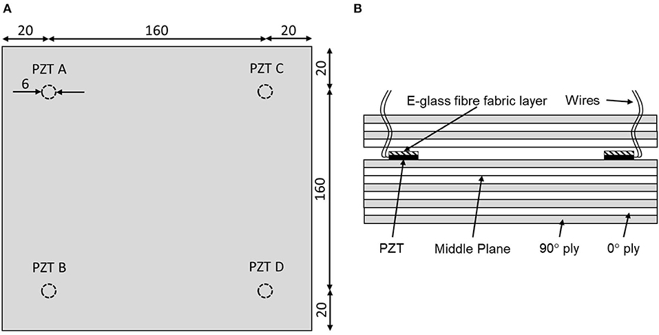
Figure 1. Positions of embedded PZTs in CFRP plate (A) and lay-up of CFRP plate (B) Dimensions in mm. Not to scale.
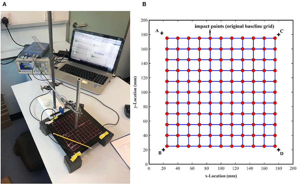
Figure 2. Experimental set-up configuration (A) and CFRP plate baseline original grid and sensor configuration (B).
The plate was suspended with four foam squares, to prevent interactions and reflections with the table. The impact signal responses from PZT sensors were acquired using a four channel PicoScope, with 8 bits of resolution, at a sampling rate of 2 MHz and an acquisition time of 50 ms. A single threshold trigger was used with a 5% pre-trigger time set to ensure the whole impulse response was captured.
To validate the robustness of the proposed work, practical experimental conditions were applied on each impact test in order to alter AE responses. These included a refining of the baseline grid (please see section Pencil Drop test and Grid Refinement) and the presence of material damage and double impacts, both causing variation of the baseline signals (please see section Double Bounce Impact and Baseline Variation With Damage).
Pencil Drop Test and Grid Refinement
The original baseline grid, in which each point pertains to a corresponding recorded impulse response, as shown in Figure 2B, relies on 121 points. In order to optimize the training process of the plate, a grid refinement factor of 2 was proposed. In this case, the concept of grid refinement factor 2 means that the number of baseline points used is reduced by 2 in relation to the original grid. Such a training corresponds to the baseline cell sides being doubled, making the baseline grid coarser and reducing the number of excitation points. Figure 3 shows the original and the refined baseline grid dimensions as well as the impact locations highlighted by the numbers. It can be observed that the impact points were increased from 100 to 125, and the number of baseline has decreased significantly from 121 to 36 points, by the grid refinement factor 2. After the training process, the original CoG method and the new topological MA approach were applied for a comparison of impact localization.
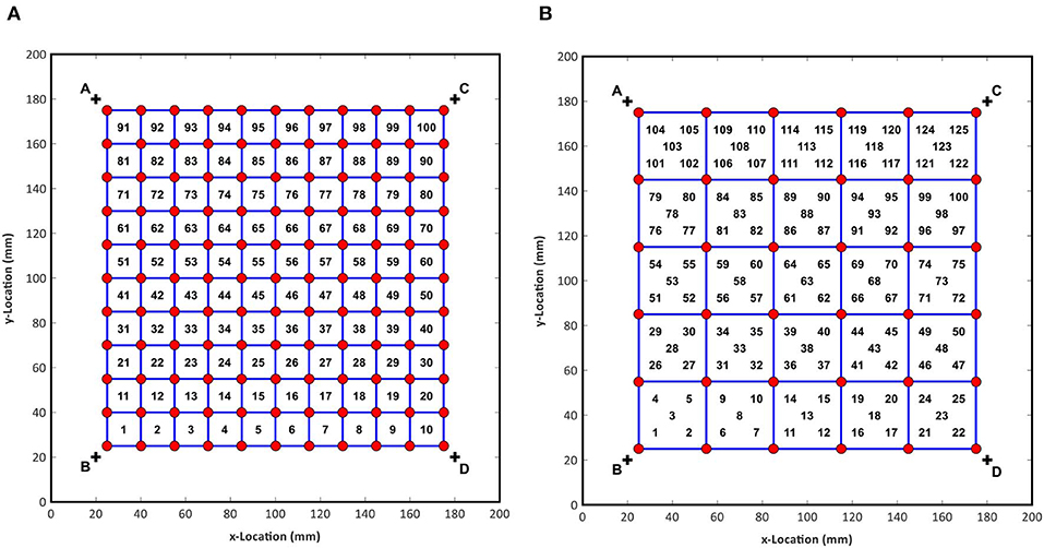
Figure 3. CFRP plate baseline grid and sensor configuration for no refinement (A) and with refinement (B).
Double Bounce Impact and Baseline Variation With Damage
Before the evaluation of the double bouncing condition, the repeatability of the proposed TR imaging process was analyzed. Theoretically, two impacts at the same location should produce the same impulsive response. This repeatability was tested for five impact points at locations shown in Figure 4A. Following impact tests, a double bouncing test was achieved in the same experimental configuration. In this case, the pencil was dropped and left to settle, not pulled back after the first bounce, resulting in double impacts in quick succession. The response was correlated to the baseline grid. Furthermore, in real aerospace applications, it is possible that the structure may develop some form of damage, which may not affect the system structurally, but it may alter the resultant wave field generated from impacts. If the elastic response is altered too, then the original baseline data will need to be recaptured, which is time-consuming. In addition, if the damage is not detected or known then the system will give incorrect impact locations without the user realizing. Therefore, in order to test how sensitive the system was to damage, a 5 mm diameter hole was drilled into the center of the plate. Impact positions were selected to show a spread of responses around the plate both near and far from the hole, according to Figure 4B.
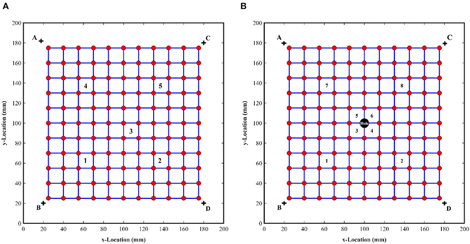
Figure 4. Impact configuration of (A) double bouncing test and (B) impact location in the damaged plate.
Impact Localization Results
Impact localization results are divided into two sub-sections. In the first one, the effectiveness of TR for impact localization with the new MA approach and embedded piezoelectric sensors were evaluated on the composite plate. Both the original and the refined grid were considered. In the second sub-section, impact localization results with double bouncing and damage test were reported.
Pencil Drop Test and Grid Refinement Results
The original baseline grid made of 15 × 15 mm cells was firstly evaluated. All impacts were aligned with the center of each cell. Results for the CoG method and the MA approach are displayed in Figures 5A,B, respectively.
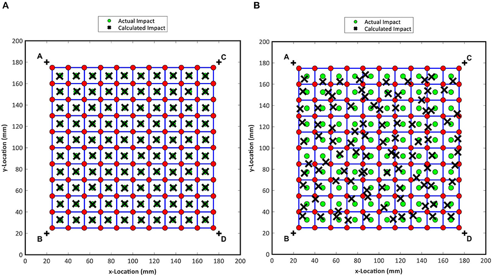
Figure 5. Calculated and actual impact locations for the CoG method (A) and the new topological MA approach (B) applied to TR with cell-centered impacts and no grid refinement.
It can be verified that, as shown in the Figure 5, the traditional CoG method presented a very small variation from the center of the predicted cells, whereas the MA technique showed variations from the center. Hence, for cell-centered impacts with the CoG method, all correct impact cells were predicted, and the mean errors and standard deviations were low in relation to the MA approach. Table 1 provides the statistical parameters and the values of CTR_GLOBAL maximum and minimum for both cases. As reported in section Traditional CoG Method, each impact can be used to generate CTR_GLOBAL values for all cells and it is the cell with the maximum CTR_GLOBAL value that becomes the predicted cell. The maximum and minimum CTR_GLOBAL values in Table 1 refer to the maximum and minimum CTR_GLOBAL values associated to each predicted cell for all impacts. The maximum and minimum CTR_GLOBAL values are useful to indicate the strength of the correlation between the impact and the recorded baseline grid, i.e., the higher the value the more likely the correct impact cell will be identified.
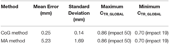
Table 1. Post-processing results for no grid refinement, CoG method and the new MA approach.
From Table 1, it can be observed that the mean error was increased from 0.25 to 5.23 mm, and the standard deviation increased from 0.14 to 1.69 mm, showing that the accuracy of the traditional CoG methodology was higher. However, for off-center impacts and larger cells the new topological MA method provided more accurate results, as observed in Figure 6 and Table 2.
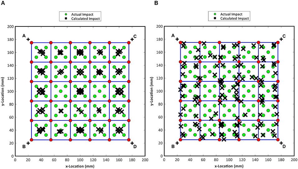
Figure 6. Calculated and actual impact locations for the CoG method (A) and the new topological MA approach (B) applied to TR with off-centered impacts and grid refinement.
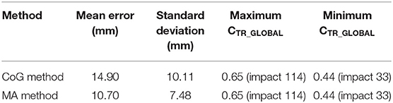
Table 2. Post processing results for grid refinement, CoG method and the new topological approach.
Results presented in Figure 6 showed that all impacts were predicted around the center of the cell with the traditional CoG method, since this methodology does not ponder the weight of each CTR value, as opposite to new topological approach. The mean error of the GoG technique was 14.9 mm against 10.7 mm of the MA method. For the standard deviation, calculated values were 10.11 mm for the GoG method and 7.48 mm for the MA technique. According to Tables 1, 2, the grid refinement decreased both maximum and minimum values of the TR correlation coefficient, as the refinement provided less data amount in relation to the original grid. However, although the mean error and standard deviation increased in relation to the denser grid, the refinement can be an alternative for systems that require less data to perform the impact localization.
From Figure 6B it is also clear that the localization for border impacts have best estimation in relation to the cell-center impacts. This results is due to the non-equilibrium of the CTR of the corners of the coarse grid. If one point dominating, showing bigger CTR values compared to the other three corners, the localization of cell-center impact lie off the correct point. To better understand this phenomenon CTR plots of the maximum and minimum predicted cell CTR_GLOBAL values are shown in Figure 7. According to the Figures 7A,B, despite the rough surface for this grid refinement, there are clear peaks that coincide with the impact locations, even for impact 19 where the predicted cells CTR_GLOBAL value is the smallest of all impacts. In relation to the Figures 7C,D, it can be seen that the peaks are becoming less prominent, especially for the minimum CTR_GLOBAL value, which corresponds to a cell-centered impact, as shown on Figure 6A, meaning the correlation to all points is reduced as fewer baseline points are as close to the actual impact location. For an impact at the corner of a cell, such as impact 114, it can be seen that one point correlates well-leading to the peak being more of a single point. This can introduce more risks as the predicted impact cell could fall incorrectly on the wrong side of this peak, especially if there is a secondary peak on that side. The new topological MA approach would compensate this error well, whereas the traditional CoG method would not. This is likely why the new MA approach revealed lower mean errors and standard deviations for the grid refinement.
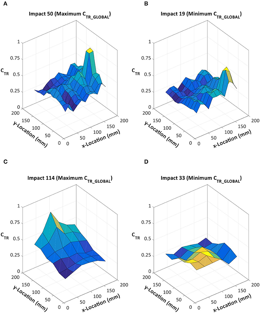
Figure 7. CTR distributions of no grid refinement for impacts associated to the maximum (A) and minimum (B) CTR_GLOBAL values and CTR distributions of grid refinement for impacts associated to the maximum (C) and minimum (D) CTR_GLOBAL.
Evaluation of the Repeatability of the TR Impact Localization Process
In this section, the repeatability of the proposed TR localization process with embedded PZT transducers was evaluated by altering the baseline signals with double bouncing tests and by introducing material damage (5 mm diameter hole) into the composite plate.
Double Bouncing Tests
Figure 8 shows the CTR values of the repeatability and double bouncing test. Results illustrate that, in relation to the repeatability test, all impacts produced the same impulsive response, since all CTR values tend to 1. In relation to the double bouncing test, the response was only slightly affected and the resulting CTR values from the correlation between the single impacts and the double impacts were all still near to one. The impact point “1” presented the lowest CTR values of the test, which were, 0.96, 0.92, and 0.96 for the sensor B, C, and D. For the other impact tests the index remained close to the unit.
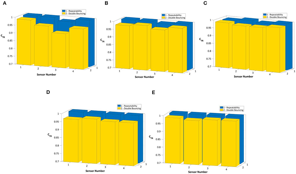
Figure 8. Repeatability test and double bouncing test for impact point 1 (A), 2 (B), 3 (C), 4 (D), and 5 (E).
Damaged Plate
Figures 9, 10 show the damaged plate impact localization with no grid refinement and the refined grid, respectively. In order to compare the influence of failure the previously trained grids with no damage condition were here considered as a baseline. TR impact localization results revealed that impact localization could be achieved also in the damaged plate. The CoG method presented better results in relation to the MA method for no grid refinement, as the mean error value and the standard deviation were lower. However, for the grid refinement condition the MA technique was more accurate, as the CoG approach tends to concentrate impacts in the center of the cell. These results were also observed in the section Pencil Drop Test and Grid Refinement Results. The statistical analysis is summarized in Table 3.
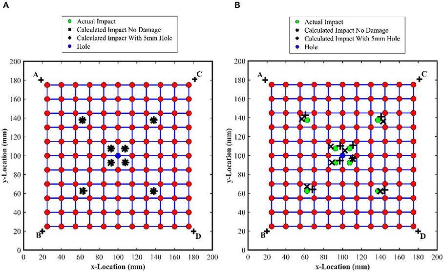
Figure 9. The CoG method (A) and the MA approach (B) applied to TR with no grid refinement in the damaged plate.
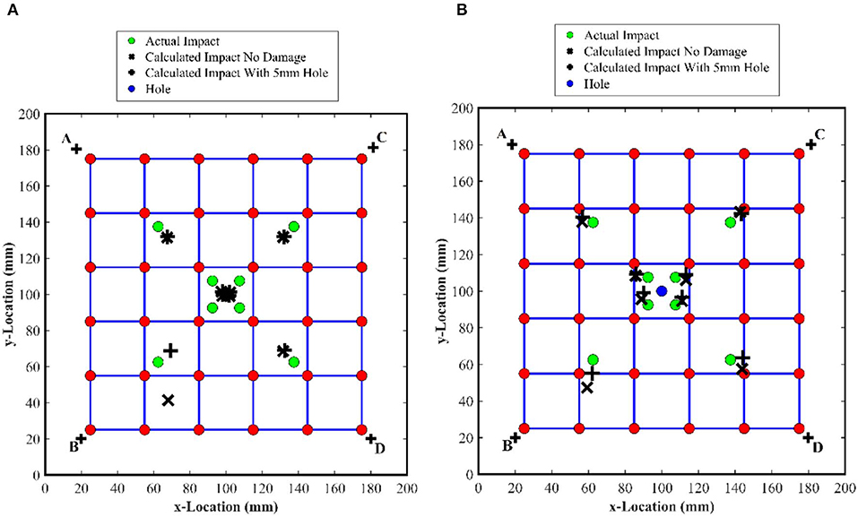
Figure 10. The CoG method (A) and the MA approach (B) applied to TR with grid refinement in the damaged plate.
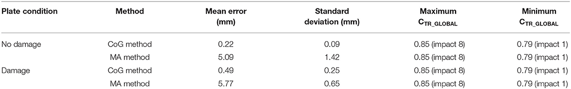
Table 3. Post-processing results for the original grid.
It can be seen that the damage increases slightly the mean error, which, for the CoG reached 0.27 mm and for the MA technique raised up to 0.69 mm. The variation in CTR distributions for impact locations relating to the maximum and minimum CTR_GLOBAL values with no damage are shown in Figure 11 for both the cases with and without damage.
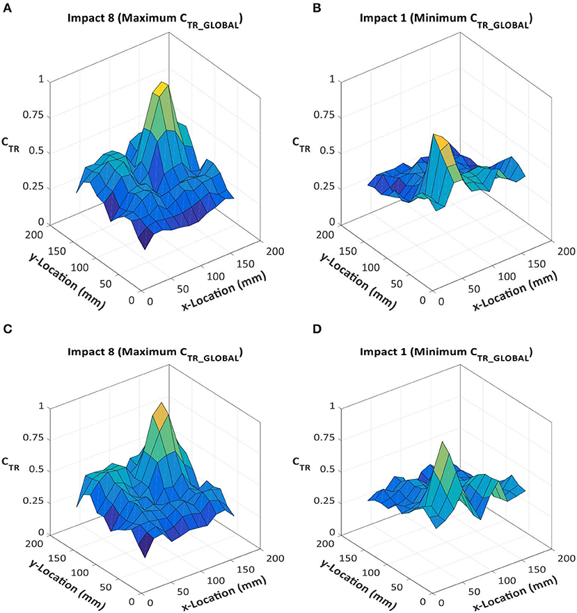
Figure 11. CTR distributions for impacts associated to the maximum and minimum CTR_GLOBAL values, and no grid refinement, both with and without damage present. (A) No damage maximum CTR_GLOBAL; (B) No damage minimum CTR_GLOBAL; (C) same impact location as (A) with damage; (D) same impact location as (B) with damage.
The location and magnitudes of peaks did not vary significantly with the presence of damage, however, the profile of the peaks did. This resulted in the same predicted impact cells being identified but variations with the predicted impact locations within them. This is particularly evident for the minimum CTR_GLOBALvalue impacts, the whole CTR distribution was altered giving the secondary peak greater magnitude. This can significantly change predicted impact locations with coarser grids when both the primary and secondary peaks are encompassed by one baseline cell. Table 4 presented the damage plate analysis for the grid refinement factor 2.

Table 4. Post processing results with grid refinement.
As reported in Table 4, although errors increased and all CTR_GLOBAL indices decreased in relation to the first grid, the MA method was more effective to accomplish the impact localization with the refined grid in the damage plate. Figure 12 shows the CTR distributions for all conditions in the damaged plate.
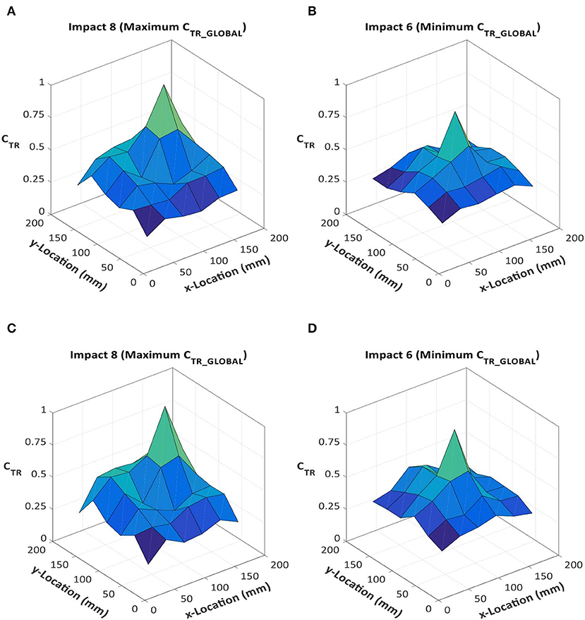
Figure 12. CTR distributions for impacts associated to the maximum and minimum CTR_GLOBAL values, combined and a grid refinement factor of 2, both with and without damage present. (A) No damage maximum CTR_GLOBAL; (B) no damage minimum CTR_GLOBAL; (C) same impact location as (A) with damage; (D) same impact location as (B) with damage.
According to Figure 12, the CTR distributions did not vary greatly with the introduction of damage, even less so than that seen with the unrefined grid. This explains why for most impacts the variation in calculated impact locations varied less for the coarse grid than that seen for the original grid.
Conclusion
This study investigated the performance of time reversal for the localization of the impact sources on a fiber reinforced plastic composite with embedded piezoelectric sensors. A topologic approach was proposed in order to enhance the accuracy of time reversal in retrieving impact location. Experimental tests were accomplished to assess the effectiveness of time reversal against many practical issues in real conditions, such as material imperfections and double bouncing, which were not consider during the initial training process. Based on the results presented, it can be concluded that the time reversal applied on a composite with embedded piezoelectric sensors proved to be an effective impact localization methodology where alterations of acoustic emission in the baseline signals are less predictable, once the impacts will be possibly distributed equally over the surface of the structure. In addition, the minimum average approach proved to be an alternative for systems that require less data to perform the impact localization. Future work will focus on the on reproducibility. This will include the use of multiple baselines and weighting functions for an improved selection of the cell under consideration for impact localization.
Data Availability Statement
The raw data supporting the conclusions of this article will be made available by the authors, without undue reservation, to any qualified researcher.
Author Contributions
AC and BC run the time reversal experiments. FB supported the development of ultrasound testing. CA manufactured the composite plate with embedded transducers. MM supported the development of time reversal theory. FC supported the development of time reversal for impact localization and led the research team.
Conflict of Interest
The authors declare that the research was conducted in the absence of any commercial or financial relationships that could be construed as a potential conflict of interest.
References
Aldaz, J., Barza, S., Fujii, M., and Moslehian, M. (2015). Advances in operator cauchy-schwarz inequalities and their reverses. Annals Funct. Anal. 6, 275–295. doi: 10.15352/afa/06-3-20
Ali, M., Joshi, S. C., and Sultan, M. T. H. (2017). Palliatives for low velocity impact damage in composite laminates. Adv. Mater. Sci. Eng. 2017, 1–17. doi: 10.1155/2017/8761479
Andreades, C., Mahmoodi, P., and Ciampa, F. (2018). Characterisation of smart CFRP composites with embedded PZT transducers for nonlinear ultrasonic applications. Compos. Struct. 206, 456–466. doi: 10.1016/j.compstruct.2018.08.083
Andreades, C., Malfense Fierro, G. P., Meo, M., and Ciampa, F. (2019). Nonlinear ultrasonic inspection of smart carbon fibre reinforced plastic composites with embedded piezoelectric lead zirconate titanate transducers for space applications. J. Intellig. Mater. Syst. Struct. 30, 2995–3007. doi: 10.1177/1045389X19873419
Atobe, S., Hu, N., and Fukunaga, H. (2011). Impact force identification of CFRP structures using experimental transfer matrices. Comput. Mater. Contin. 26, 67–90. doi: 10.3970/cmc.2011.026.067
Baccar, D., and Söffker, D. (2017). Identification and classification of failure modes in laminated composites by using a multivariate statistical analysis of wavelet coefficients. Mech. Syst. Signal Proc. 96, 77–87. doi: 10.1016/j.ymssp.2017.03.047
Bas, P. Y. L., Ulrich, T. J., Anderson, B. E., Guyer, R. A., and Johnson, P. A. (2011). Probing the interior of a solid volume with time reversal and nonlinear elastic wave spectroscopy. J. Acoust. Soc. Am. 130, 1–7. doi: 10.1121/1.3638926
Bianchi, D., Mayrhofera, E., Betz, M. G. G, and Vernes, A. (2015). Wavelet packet transform for detection of single events in acoustic emission signals. Mech. Syst. Signal Proc. 64-65, 441–451. doi: 10.1016/j.ymssp.2015.04.014
Birman, V. (1996). Thermal effects on measurements of dynamic processes in composite structures using piezoelectric sensors. Smart Mater. Struct. 5, 379–385. doi: 10.1088/0964-1726/5/4/001
Castro, B. A., Baptista, F. G., Ulson, J. A. C., Alves, A. F., Clerice, G. A., Hernandez, B., et al. (2018). “Structural damage location by low-cost piezoelectric transducer and advanced signal processing techniques,” in Proceedings of The 5th International Electronic Conference on Sensors and Applications, Vol. 4, 1–6. doi: 10.3390/ecsa-5-05725
Castro, B. A. d, Baptista, F. G., and Ciampa, F. (2019). Comparative analysis of signal processing techniques for impedance-based SHM applications in noisy environments. Mech. Syst. Signal Proc. 126, 326–340. doi: 10.1016/j.ymssp.2019.02.034
Chandrashekhar, M., and Ganguli, R. (2016). Damage assessment of composite plate structures with material and measurement uncertainty. Mech. Syst. Signal Proc. 75, 75–93. doi: 10.1016/j.ymssp.2015.12.021
Chen, B., Hei, C., Luo, M., Ho, M., and Song, G. (2018). Pipeline two-dimensional impact location determination using time of arrival with instant phase (TOAIP) with piezoceramic transducer array. Smart Mater. Struct. 27, 1–12. doi: 10.1088/1361-665X/aadaa9
Chen, C., Li, Y., and Yuan, F.-G. (2012b). Impact source identification in finite isotropic plates using a time-reversal method: experimental study. Smart Mater. Struct. 21:10. doi: 10.1088/0964-1726/21/10/105025
Chen, C., Li, Y., and Yuan, F. G. (2012a). Development of time-reversal method for impact source identification on plate structures. Shock Vibr. 20, 561–573. doi: 10.1155/2013/312169
Chen, C., and Yuan, F. G. (2010). Impact source identification in finite isotropic plates using a time-reversal method: theoretical study. Smart Mater. Struct. 19, 1–11. doi: 10.1088/0964-1726/19/10/105028
Ciampa, F., Boccardi, S., and Meo, M. (2016). Factors affecting the imaging of the impact localisation with inverse filtering and diffuse wave fields. J. Intell. Mater. Syst. Struct. 27, 1523–1533. doi: 10.1177/1045389X15596622
Ciampa, F., and Meo, M. (2010a). Acoustic emission source localization and velocity determination of the fundamental mode A0 using wavelet analysis and a Newton-based optimization technique. Smart Mater. Struct. 19, 1–14. doi: 10.1088/0964-1726/19/4/045027
Ciampa, F., and Meo, M. (2010b). A new algorithm for acoustic emission localization and flexural group velocity determination in anisotropic structures. Compos A 41, 1777–1786. doi: 10.1016/j.compositesa.2010.08.013
Ciampa, F., and Meo, M. (2011). Acoustic emission localization in complex dissipative anisotropic structures using a one-channel reciprocal time reversal method. J. Acoust. Soc. Am. 130, 168–175. doi: 10.1121/1.3598458
Ciampa, F., and Meo, M. (2012). Impact detection in anisotropic materials using a time reversal approach. Struct. Healthy Monitor. 11, 43–49. doi: 10.1177/1475921710395815
Ciampa, F., and Meo, M. (2014). Impact localization on a composite tail rotor blade using an inverse filtering approach. J. Intell. Mater. Syst. Struct. 25, 1950–1958. doi: 10.1177/1045389X13512904
Ciampa, F., Meo, M., and Barbieri, E. (2012). Impact localization in composite structures of arbitrary cross section. Struct. Health Monitor. 11, 643–655. doi: 10.1177/1475921712451951
Clausen, J., Specht, U., Busse, M., Lang, A., and Sandersb, J. (2013). Integration of glass fibre structures in aluminium cast parts for CFRP aluminium transition structures. Proc. Mater. Sci. 2, 197–203. doi: 10.1016/j.mspro.2013.02.024
Das, A. K., and Leung, C. (2018). A new power-based method to determine the first arrival information of an acoustic emission wave. Struct. Health Monitor. 18, 1–13. doi: 10.1177/1475921718815058
De Simone, M., Ciampa, F., and Meo, M. (2018). A hierarchical method for the impact force reconstruction in composites structures. Smart Mater. Struct. 1, 1–36. doi: 10.1088/1361-665X/aae11c
Emanuele, S., Francesco, C., Boccardi, S., and Meo, M. (2017). Impact source localisation in aerospace composite structures. Smart Mater. Struct. 26, 1–13. doi: 10.1088/1361-665X/aa973e
Haider, M. F., Migot, A., Bhuiyan, M. Y., and Giurgiutiu, V. (2018). Experimental investigation of impact localization in composite plate using newly developed imaging method. Inventions 3, 1–14. doi: 10.3390/inventions3030059
Huang, L., Du, J., Chen, F., and Zeng, L. (2019). An efficient time reversal method for lamb wave-based baseline-free damage detection in composite laminates. Appl. Sci. 9:11. doi: 10.3390/app9010011
Huang, Y., and Nemat-Nasser, S. (2007). “Structural integrity of composite laminates with embedded micro-sensors,” in Sensor Systems and Networks: Phenomena, Technology, and Applications for NDE and Health Monitoring, ed J. P. Kara (San Diego, CA: SPIE). doi: 10.1117/12.715221
Ing, R. K., and Quieffin, N. (2005). In solid localization of finger impacts using acoustic time-reversal process. Appl. Phys. Lett. 87, 1–3. doi: 10.1063/1.2130720
Kim, H. W., and Yuan, F. G. (2018). Enhanced damage imaging of a metallic plate using matching pursuit algorithm with multiple wavepaths. Ultrasonics 89, 84–101. doi: 10.1016/j.ultras.2018.01.014
Kim, J. H., Kim, Y. Y., Park, Y., and Kim, C. G. (2015). Low-velocity impact localization in a stiffened composite panel using a normalized cross-correlation method. Smart Mater. Struct. 24, 1–13. doi: 10.1088/0964-1726/24/4/045036
Kundu, T. (2012). “A new technique for acoustic source localization in an anisotropic plate without knowing its material properties,” in Proceedings of the 6th European Workshop on Structural Health Monitoring (Dresden). Available online at: http://www.ndt.net/?id=14004
Kundu, T., Nakatani, H., and Takeda, N. (2012). Acoustic source localization in anisotropic plates. Ultrasonics 52, 740–746. doi: 10.1016/j.ultras.2012.01.017
Li, Y., Yu, S., Dai, L., Luo, T., and Li, M. (2018). Acoustic emission signal source localization on plywood surface. J. Wood Sci. 64, 78–84. doi: 10.1007/s10086-017-1672-x
Marchi, L. D., Marzani, A., Speciale, N., and Viola, E. (2011). A passive monitoring technique based on dispersion compensation to locate impacts in plate-like structures. Smart Mater. Struct. 20:9. doi: 10.1088/0964-1726/20/3/035021
McLaskey, C. (2010). Beamforming array techniques for acoustic emission monitoring of large concrete structures. J. Sound Vibr. 329, 2384–2394. doi: 10.1016/j.jsv.2009.08.037
Morse, L., Khodaei, Z. S., and Aliabadi, M. H. (2018). Reliability based impact localization in composite panels using Bayesian updating and the Kalman filter. Mech. Syst. Signal Proc. 99, 107–128. doi: 10.1016/j.ymssp.2017.05.047
Park, B., Sohn, H., Olson, S. E., DeSimio, M. P., Brown, K. S., and Derriso, M. M. (2012). Impact localization in complex structures using laser-based time reversal. Struct. Health Monitor. 5, 577–588. doi: 10.1177/1475921712449508
Qiao, B., Liu, J., Liu, J., Yang, Z., and Chen, X. (2019). An enhanced sparse regularization method for impact force identification. Mech. Syst. Signal Proc. 126, 341–367. doi: 10.1016/j.ymssp.2019.02.039
Qiu, B., Zhang, M., Xie, Y., Xianqiang, Q., and Li, X. (2019). Localisation of unknown impact loads on a steel plate using a pattern recognition method combined with the similarity metric via structural stress responses in the time domain. Mech. Syst. Signal Proc. 128, 429–445. doi: 10.1016/j.ymssp.2019.04.015
Qiu, L., Yuan, S., Zhang, X., and Wang, Y. (2011). A time reversal focusing based impact imaging method and its evaluation on complex composite structures. Smart Mater. Struct. 20, 1–11. doi: 10.1088/0964-1726/20/10/105014
Remillieux, M., Andersona, B., Ulrich, T. J., Bas, P. Y. L., and Payan, C. (2015). Depth profile of a time-reversal focus in an elastic solid. Smart Mater. Struct. 58, 60–66. doi: 10.1016/j.ultras.2014.12.003
Seno, A. H., Khodaei, Z. S., and Aliabadi, M. F. (2019). Passive sensing method for impact localisation in composite plates under simulated environmental and operational conditions. Mech. Syst. Signal Proc, 129, 20–36. doi: 10.1016/j.ymssp.2019.04.023
Tian, Y., Zhang, J., and Yub, S. (2019). Vision-based structural scaling factor and flexibility identification through mobile impact testing, Mech. Syst. Signal Proc. 122, 387–402. doi: 10.1016/j.ymssp.2018.12.029
Tobias, A. (1976). Acoustic-emission source location in two dimensions by an array of three sensors. Non-Destruct. Test. 9, 1, 9–12. doi: 10.1016/0029-1021(76)90027-X
Wang, C. H., Rose, J. T., and Chang, F. K. (2004). A synthetic time-reversal imaging method for structural health monitoring. Smart Mater. Struct. 13, 415–423. doi: 10.1088/0964-1726/13/2/020
Xu, L., Wang, Y., Cai, Y., Wu, Z., and Peng, W. (2016). Determination of impact events on a plate-like composite structure. Aeronaut. J.1228, 984–1004. doi: 10.1017/aer.2016.36
Yin, S., Cui, Z., Fu, J., and Kundu, T. (2019). Acoustic source localization in heterogeneous media, Ultrasonics, 99:105957. doi: 10.1016/j.ultras.2019.105957
Zhou, Z., Cheng, R., Rui, Y., Zhou, J., and Wang, H. (2019). An improved automatic picking method for arrival time of acoustic emission signals. IEEE Access. 7, 75568–75576. doi: 10.1109/ACCESS.2019.2921650
Keywords: time reversal signal processing, impact localization, embedded sensors, piezoelectric transducers, composite plates
Citation: Coles A, de Castro BA, Andreades C, Baptista FG, Meo M and Ciampa F (2020) Impact Localization in Composites Using Time Reversal, Embedded PZT Transducers, and Topological Algorithms. Front. Built Environ. 6:27. doi: 10.3389/fbuil.2020.00027
Received: 11 December 2019; Accepted: 25 February 2020;
Published: 17 March 2020.
Edited by:
Eleni N. Chatzi, ETH Zürich, SwitzerlandReviewed by:
Weigang Yang, University of California, Santa Cruz, United StatesInka Mueller, Bochum University of Applied Sciences, Germany
Copyright © 2020 Coles, de Castro, Andreades, Baptista, Meo and Ciampa. This is an open-access article distributed under the terms of the Creative Commons Attribution License (CC BY). The use, distribution or reproduction in other forums is permitted, provided the original author(s) and the copyright owner(s) are credited and that the original publication in this journal is cited, in accordance with accepted academic practice. No use, distribution or reproduction is permitted which does not comply with these terms.
*Correspondence: Francesco Ciampa, Zi5jaWFtcGFAc3VycmV5LmFjLnVr