
94% of researchers rate our articles as excellent or good
Learn more about the work of our research integrity team to safeguard the quality of each article we publish.
Find out more
METHODS article
Front. Built Environ., 28 February 2020
Sec. Bridge Engineering
Volume 6 - 2020 | https://doi.org/10.3389/fbuil.2020.00014
This article is part of the Research TopicDiagnostic and Proof Load Tests on BridgesView all 16 articles
 Jacob Wittrup Schmidt1*Sebastian Thöns1,2Medha Kapoor1Christian Overgaard Christensen1Svend Engelund3John D. Sørensen4
This paper reviews historical developments and recent challenges in full scale bridge testing and introduces results- and hypotheses related to an ongoing bridge testing research project. This research project encompasses full scale bridge testing in conjunction with bearing capacity analysis as well as related contact- and non-contact monitoring procedures combined with a decision analytical approach. Results from the first steps of the project, focusing on full scale load testing of bridges, are presented. The next part approaches the interfaces between three project areas namely the bearing capacity analysis, the utilization of monitoring procedures and a decision analytical approach. The proposed probabilistic decision analysis approach is described for two scenarios: (1) The decision support for the actual proof load test providing decision rules for a safe and efficient in-situ test and (2) for the identification of efficient strategies for the bridge reclassification accounting for modeling, simulation, and monitoring information. The paper concludes with a summary highlighting deemed challenges in the used approaches.
The road authorities in most countries face problems related to aging bridges and increased traffic intensity and traffic loads. The aging infrastructure was originally designed according to old codes that were developed at a time when the traffic loads were considerably lower than today. Hence, the road authorities must choose between three different options:
1. Impose restrictions to the traffic on the bridge (maximum limit for axle loads or the total weight of the vehicles using the bridge)
2. Strengthen the bridge
3. Perform tests and analyses that demonstrate that the load carrying capacity of the bridge is acceptable.
The costs related to traffic restrictions or a bridge strengthening are usually relatively high compared to the cost of the tests and analyses that may demonstrate that the load carrying capacity of the bridge is acceptable. Therefore, the road authorities will usually choose the third option.
The road authorities may perform tests to determine the properties of materials such as concrete, reinforcement or steel. The results of these tests may be used to determine more accurate estimates of the relevant material properties.
In addition, one of the tests available to the road authorities is full scale bridge testing. Full scale bridge testing has the advantage that it provides increased information accuracy with respect to the actual response and load carrying capacity of the considered bridge. There are two different approaches to full scale bridge testing:
(1) Proof loading, which is performed in the linear elastic regime up to a pre-defined proof load magnitude. As large loads are needed for proof load testing, the associated risks can be large. Therefore, the structural response must be followed closely during testing. If the bridge can withstand the pre-defined proof load without signs of distress, the capacity is experimentally proven. Normally pre-defined stop criteria and target load are decided upon in order to ensure that no permanent damage occurs. If the structural response exceeds the pre-defined stop criteria or target load, the proof load test must be terminated and no further loading is allowed.
(2) Failure loading, where loading is applied to evaluate the full response of a certain bridge type. More information concerning the boundary conditions, governing failure modes, interaction between structural elements etc. can be evaluated by using this approach. However, permanent damage of the bridge structure is the outcome of such testing and, as a result, demolishing of the structure.
Often failure loading shows that the capacity is higher than expected in the tested bridge structures, since uncertainties related to the overall structural behavior, materials, modeling approach etc., are reduced compared to prior models.
However, the real ultimate capacity of tested bridges is often up to discussion, since testing of bridges intended for continued service do not allow permanent damage. Consequently, the margin between the predicted capacity and real ultimate capacity is unknown and can differ depending on the bridge type.
Bridge load testing to failure was already initiated in 1913, where testing was performed on a flat arch bridge (Elmont, 1913). The highest value of the compressive stresses was reached via a concentrated load over the center of one part of the arch.
Later, in 1952, a three span concrete bridge was tested to failure in the UK. The bridge was a pre-stressed three span pedestrian foot bridge located at the South Bank. Failure occurred at a dead load of approximately 2.4 times the design load and lasted for ~3 days (Civil Engineering Review, 1952).
Dead loading was the main loading type until 1963, where Rösli (1963) used hydraulic jacks. This was one of the first applications, where such loading method was used and it was reported that the ultimate failure load reached the same level as foreseen in the theoretical evaluations.
In 1968, Gosbell and Stevens (1968) loaded a pre-stressed I-beam bridge with an in-situ cast concrete bridge deck. The ultimate punching shear of the one-span bridge was stated to correlate well with theory. It was however reported that a three time higher cracking load, than predicted, was applied to initiate cracking.
Load simulating different wheel pressures was performed in 1973 by Goodpasture and Burdette (1973). It was stated that the applied theory correlated well with the measured results. Additionally the AASHO showed predictions, which were approximately half of the measured values. Jorgenson and Larson (1976) however reported loads which reached nearly 5.5 times the characteristic traffic load. Furthermore, load testing was performed by Nanni et al. (1999), Alkhrdaji et al. (2001), Zhang et al. (2011, 2013), and Lantsoght (2013).
It is seen from the literature that the aim of the research projects differ greatly. Most of the projects succeeded in testing the bridges to failure but the ultimate failure testing approaches are fragmented. Consequently, the approaches and results are based on separate assumptions depending on the actual project and bridge design.
Some of the research programs aimed at implementing the obtained knowledge into national codes. However, it is normally not reported if they succeeded in this, which could be dedicated to the fact that only a limited number of bridges were tested and reported together (mostly only 1 bridge per publication).
Additionally no sufficient method to find the link between material testing, sub component testing and full scale testing, seem to exist.
A number of suggestions were given to explain a higher test capacity when comparing with theory (Strain hardening, conservative load distribution etc.). The research projects do, however, not include any evaluations of the magnitude of these contributions.
Several types of monitoring approaches were used in the described research projects to evaluate the response until failure. Mostly contact monitoring methods were used, whereas application of more novel approaches such as acoustic emission, laser-, radar-, DIC systems, etc. are limited, all though research is ongoing in this regard.
It is seen that monitoring plays an essential role when performing bridge testing, since global and local thresholds have to be evaluated as a mean to find the stop criterion. In addition, results from the applied measurement equipment can be used to verify- or falsify the theoretical evaluations and thus for calibration. Consequently, the evaluation of a bridge structure seems to be an iterative process, where several parameters can influence and potentially change the final decision regarding a stop criterion. This depends on the monitored responses and calibrated theoretical models.
For diagnostic and proof load testing, a number of national guidelines exists. In North America the Manual for Bridge Evaluation (AASHTO, 2011), based on the Manual for Bridge Rating through Load Testing (NCHRP, 1998) gives recommendations for diagnostic testing and for determining the target proof load in proof load tests of bridges, however no stop criteria are defined. The ACI 437.2M-13 (ACI Committee 437, 2013) define both loading protocol and stop criteria (“acceptance criteria” in ACI) for buildings, but not for bridges. In Europe, Germany (DAfStb, 2000), Ireland (NRA, 2014), and Great Britain (ICE, 1998) among others have national guidelines for load testing, but only the German guideline prescribe stop criteria, again for buildings.
Since bridges are complex structures to evaluate, it is still up to discussion how stop criteria can be defined. Additionally, such thresholds should be evaluated to an extent that provides comfort in a final decision taking regarding the target load magnitude—the bridge might not behave as expected when loading is applied in-situ.
Motivated by the absence of applicable guidelines (Lantsoght et al., 2018) presents a proposal for stop criteria in proof load testing of reinforced concrete slab bridges. The proposal provides a solid base for further development, but the thresholds seems not yet evaluated to a satisfactory extent in regards to decision taking.
Some of the outlined challenges are addressed in an ongoing research project. This project is so far focussed on the development of an efficient in-situ full scale testing procedure and will be extended to address the combination of proof loading and the realistic simulation of the ultimate capacity behavior (Serviceability limit state- and ultimate limit state) and decision approaches.
This paper provides an overview of the current project achievements in regard to the testing procedure and test results and contains a proposal relating to a probabilistic decision approach as an iterative process, where two scenarios can be described and analyzed: (1) The decision support for an actual proof load test providing decision rules for a stop criterion and thus safe and efficient in-situ testing, and (2) for the identification of efficient strategies for the bridge reclassification accounting for modeling, simulation, and monitoring information.
The research project considered for the probabilistic and theoretical decision approach is a part of an ambitious research project initiated in 2016 in Denmark concerning full-scale testing of one-span concrete slab bridges with maximum span of 12 m (39.4 feet). Some of the initial main milestones as well as related research questions of the project are the following:
- Development of a full-scale test method: Is it possible to construct a test rig, which meets the demands to a high loading magnitude combined with a fast and precise in-situ full-scale test?
- Simplified monitoring: Is it possible to optimize advanced monitoring to a level, where measurements are performed in a fast- and simplified way, and at the same time reveal governing thresholds related to the needed stop criterions?
- Calibration of theoretical models: Can advanced theoretical models be presented in a more abridged way, where it is calibrated, via input from in-situ testing, to the developed monitoring method?
In the following, the development of a full-scale test method is described together with a conceptual approach of how to address a systematic reclassification of bridges as decision analysis combined with monitoring and further evolution of theoretical models.
A reclassification can be relevant to perform when there are uncertainties associated with the original capacity evaluation or the current state of an aging bridge. From a bridge owner's perspective, the goal usually is to verify the current bridge class or to obtain a higher class to meet a higher traffic demand.
When performing full-scale load testing, the loading setup should comply with national guidelines. One of the challenges in this approach, is to apply load configurations that accurately reflects axle- and wheel loading described in the Danish bridge classification system (Danish Road Directorate, 2009). Figure 1 shows an example of a classification vehicle (class 100 ton vehicle) with related axle load magnitudes, distances and geometries and with a distributed surface load, p.
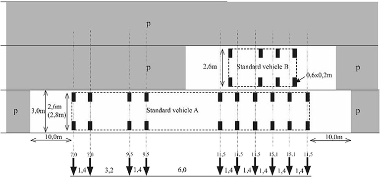
Figure 1. Example of a classification vehicle—in this case a class 100-ton vehicle.
The classification system describes the vehicle class with related axle configurations and load magnitudes. It is seen that a vehicle A- and B should be placed adjacent to each other and in the most undesirable way when applied to a given bridge structure.
When the load configurations are applied to short span bridges, it is often seen that the vehicle is too long for the bridge. Consequently, the rear axle represent the loading from the vehicle, since it provides the highest load magnitude. The combination of vehicle A- and B including safety factors should be less than the bridge capacity and as a result the bridge class is found.
Vehicle B always represents a fixed load. For the highest bridge class, vehicle B can reach an axle load of 11.8 tons. Vehicle A can reach an axle load up to 23.7 tons (without safety factors).
A novel test rig was developed specially to comply with these demands, and thereby enabled loading precisely as described in the Danish classification system. The loading rig is depicted in Figure 2. The rig applies an accurate vehicle A- and B load, by use of hydraulic jacks and dead loading. The hydraulic jacks are placed between the loading frames and main girder, whereas the dead load is applied directly on the vehicle A- and B loading frames. This configuration ensures a flexible high magnitude loading and enable a precise semi-deformation controlled loading (Schmidt et al., 2018).
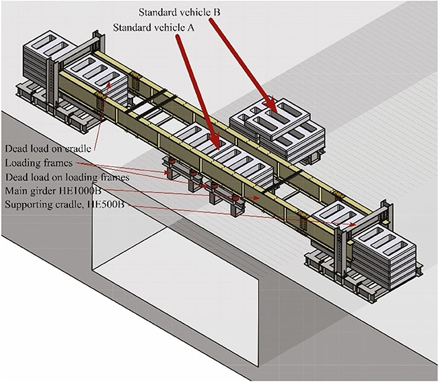
Figure 2. Loading rig.
The precision of the loading application is paramount for the probabilistic- and theoretical decision approach, which is dependent on the two components of load and resistance. With a precise loading application, the uncertainties connected with the load component are small, consequently resulting in a significant reduction of the overall model uncertainty. In addition, the code prescribes load values, but do not define the frequency of the load occurrence. When performing life cycle oriented decision analyses, such input is extremely relevant as well. So far, several one span bridges have been tested using the developed test rig. Two of the bridges had a span of ~11 m, for which the monitoring setup consisted of a land surveyor, LVDTs, distance lasers, digital image correlation (DIC) as well as output from the separately controlled hydraulic jacks and deformation measurements between the test rig parts (see Halding et al., 2017; Schmidt et al., 2018).
The bridges consisted of pre-stressed OT-beams (overturned T-beams) with in-situ concrete cast on top, a bitumen layer, protective concrete layer and finally asphalt.
Testing was performed within 1 day and the test rig applied an axle load of approximately 100 ton (test rig limit) without reaching failure, which is more than four times the highest axle load described in the classification system.
It was observed that in-situ monitoring during testing can be challenging. Most of the monitoring equipment are originally intended for controlled laboratory use and thus susceptible to in-situ environment and challenges related to a tight time schedule. However, it was still possible to obtain promising results and strong indications. The usability and precisions of the monitoring methods on larger structures and in in-situ conditions are presently being evaluated in detail.
As for the load application, a good precision of the monitoring equipment is essential as a mean to calibrate the theoretical model and as input in the probabilistic model. Another important monitoring output is indicative occurrences, which can be used as both stop criteria and/or input in theoretical models, which can be updated during testing. An example of an indicative occurrence could be the detection of a crack in a certain zone or indications of initial damage occurrence. When deciding if further loading should be applied during testing, the upcoming loading step would then be concluded upon by the use of several input parameters and not a single threshold alone. In addition, it is in this case assumed that the load-deformation relationship (i.e., ductile or brittle behavior) is evaluated and decided upon. This concept is proposed as a first step toward a systematic bridge classification method, where (1) an iterative calibration of the theoretical model, (2) close monitoring of stop criteria including continuous updating from the theoretical model, and (3) probabilistic models continuously updated with input from the theoretical model and from monitoring, which consequently provides approval for an upcoming load step during testing.
A systematic and network-wise reclassification may be achieved by a combination of methods, approaches and technologies with a linked research synergy, Figure 3. This includes development of (1) modeling and simulation techniques especially for more realistic models of the structural behavior, (2) tailored testing strategies in combination with advanced monitoring and (3) probabilistic and decision analyses to combine modeling, testing, and performance information as well as to identify efficient strategies for next load step approval and thus reclassification. The interfaces between the project areas “Modeling and simulation,” “Testing and monitoring,” and “Probabilistic and decision analyses” are very relevant for the success of the overall and the individual project areas. Figure 3 contains the approach and lists keywords for interactions between the linked research areas.
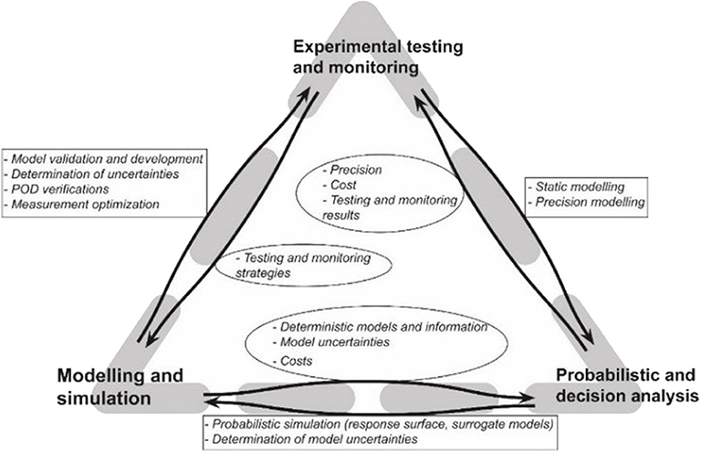
Figure 3. Approach for systematic bridge classification with interfaces between project areas.
The area “Probabilistic and decision analyses” can support “Modeling and simulation” and “Testing and monitoring” with expertise on:
(1) statistical, probabilistic and uncertainty (or precision) modeling to analyze measurement results,
(2) how to combine probabilistic and simulation models and
(3) how to determine model uncertainties.
The project area “Probabilistic and decision analyses” needs support from “Modeling and simulation” in terms of:
(1) the integration of the information type (e.g., model parameter, random variable, indication or capacity) in the probabilistic models,
(2) the monetarization of the human, software and hardware resources
(3) the quantification of the model- and physical structural uncertainties.
The project area “Probabilistic and decision analyses” needs support from “Testing and monitoring” in terms of:
(1) the experimental outcomes and related precision,
(2) the quantification of the testing, monitoring and operational uncertainties
(3) the monetarization of the needed analyses, human and testing resources.
The interface between “Probabilistic and decision analyses” and “Testing and monitoring” are here further elaborated upon, for explanatory purposes.
The experimental outcomes are the overall result of testing, which can roughly be described as: (1) Brittle collapse, without warning, (2) Occurrence of irreversible damage, which is not detected by monitoring in time, and (3) A successful test, where the target load is reached or the loading is stopped in time to prevent irreversible damage.
The quantification of the testing, monitoring and operational uncertainties are comprehensive to describe, but considers essential input parameters for the probabilistic model. Considering stop criteria and measurement equipment, the stop criteria recently proposed in Lantsoght et al. (2018) are shown in Table 1. Criteria are proposed for both bending and shear failure, though it is stated that the criteria for shear needs further research. However, the uncertainties connected to the criteria are not quantified toward probabilistic model input based on the applied monitoring equipment. When considering strain levels or crack widths in a test and the criteria values are reached, it is paramount to know the probability, that the measured value is equal to the true value. In an in-situ environment, this can sometimes be a significant challenge. In connection with the proposed stop criteria it is also stated, that in bridge tests performed to failure, the loading would have been stopped at 60–70% of the maximum applied load when applying the proposed criteria. The safety/risk in this is described as being “not overly conservative,” which seems to reveal a need for a quantification to an input value applicable in a decision analysis. Input for this could be the generated from the “Modeling and simulation” area.
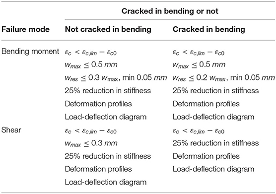
Table 1. Recommendations for stop criteria for proof load testing (Lantsoght et al., 2018).
An alternative stop criteria could be the detection of crack formation, which also presents a need for quantification of two parameters needed in the probabilistic analysis; (1) the probability of detection of a crack, and (2) the probability that the detected actually is a crack and not a false positive, both given a pre-defined threshold.
The monetarization of the needed analyses in terms of human and testing resources are needed in the decision analysis to match risk with cost for the most profitable decision.
In the context of probabilistic and decision analyses, this section provides a starting point for a decision analytical approach for bridge reclassification, i.e., for the combination of all relevant information to reduce uncertainties related to the performance of bridges and the identification of cost- and risk efficient reclassification strategies building upon Thöns (2018). The decision analytic approaches takes basis in the Bayesian decision theory, see e.g., Raiffa and Schalifer (1961) and Benjamin and Cornell (1970), and the utility theory, see Von Neumann Morgenstern (1947). The framework encompasses (1) proof loading information on component and system level, (2) outcomes of laboratory tests on component and subsystem level, (3) modeling and simulation information with various refinement levels and (4) a combination of these strategies. In the scientific literature, the stated elements of the framework have been analyzed separately and not integrally [see e.g., Yang (1976), Lin and Nowak (1984), Rackwitz and Schrupp (1985), Diamantidis (1987), Fu and Tang (1995), Saraf and Nowak (1998), Faber et al. (2000), Ersdal et al. (2003), Nishijima and Faber (2007), Sørensen and Toft (2010), Thöns et al. (2011), Casas and Gómez (2013), Gutermann and Schröder (2015), Brüske and Thöns (2016), Lantsoght et al. (2016, 2017)].
The decision process is subdivided into two interconnected decision situations. Decision situation 1 constitutes the efficient planning and performance of the proof loading and the prevention of bridge damage. Decision situation 2 constitutes decision about the most efficient bridges reclassification strategy encompassing proof loading, laboratory testing and advanced modeling and simulation.
For decision situation 1, the decision maker is the planner of the proof loading. The decision maker chooses the loading level, the monitoring technologies and methods as well as the stop criteria to minimize the expected costs of the test and to comply with the acceptable risks.
The decision tree in Figure 4 illustrates the decision process with decision nodes (rectangles) which refer to the choices. The chance nodes (circles) represent the most relevant uncertainties associated to the choices, i.e., the decision variables, and encompass testing, monitoring, operational, model, statistical, and structural uncertainties. The temporal dimension added to the decision scenario illustrates the effects of the proof load testing on the expected life cycle costs of the bridge through the updated failure probabilities and subsequent risk reduction. The connections in the decision tree are representative of the effect of the proof loading survival outcome on the bridge probability of failure in the year(s) following the testing. The optimization is performed with consideration to the target reliability levels recommended by for e.g., the probabilistic model code [Joint Committee on Structural Safety (JCSS), 2001], which serve as boundaries for the decision analysis.
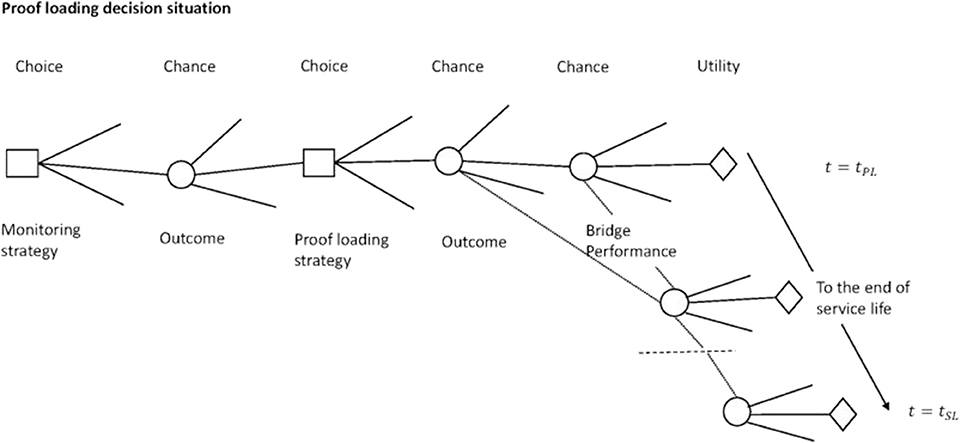
Figure 4. Illustration of decision situation 1: proof loading of the bridge with a decision tree encompassing the choice of the proof loading and monitoring strategy.
Decision situation 2 is subdivided into the information acquirement phase and the bridge utilization phase. The decision maker is here the planner of the reclassification and can select the combination of the in-situ proof loading, experimental testing and simulation strategies. The objective is the maximization of the expected benefits with the reclassification of a bridge in combination with the least expected costs for the proof loading, laboratory testing and the modeling information.
The information acquirement phase encompasses the modeling and simulation, experimental testing and proof loading approaches. For modeling and simulation, the decision variables are represented by the modeling approaches and simulations with various refinement levels. The precision of these models and simulations are described with model uncertainties. The experimental testing includes different strategies such as e.g., laboratory testing of sub-systems and components as well as material parameters as decision variables. The outcomes of the experimental testing are described with the uncertainties associated to the experiments and tests accounting for the measurement uncertainties and the operational uncertainties. Proof loading encompasses various proof loading strategies on system, sub-system and component level and the associated uncertainties together with monitoring during the proof loading test (see decision scenario 1).
The utilization phase contains the load bearing capacity, i.e., the classification of the bridge, as the decision variable and the uncertain performance in the remaining service life including e.g., the gathered information and degradation. The bearing capacity choice includes e.g., the choice of an increased load rating for the bridge. Utilities, i.e., expected benefits and expected cost as well as risks are associated to the decision variables, i.e., the information acquirement strategies, and the bearing capacity class and the operational costs throughout the service life. For a full-scale proof load test, the risk of structural failure is part of the consequence and follow-up consequence modeling.
As an illustration, decision situation 1 is expanded upon with an example to demonstrate the probabilistic and decision framework and the interface between project areas of “Probabilistic and decision analyses” and “Testing and monitoring.” Let us consider a deteriorated bridge at an advanced age, having completed 85 years of its' planned service life of 100 years (tSL). It is planned to perform a full scale proof loading of the bridge in order to assess the reliability of the structure. The decision scenario considers the proof load test planner who seeks to identify the optimal proof loading strategy, monitoring method and technology as well as the stop criteria that lead to an efficient and safe testing. The decision situation is considered in the following sections first with a prior decision analysis where the benefit gain from performing a full-scale proof loading is assessed. Here, the performance of the bridge is modeled by calculating its annual probability of failure. The outcome of a proof load testing with different proof load levels is predicted and a decision analysis is performed to identify the optimal proof load level as the one leading to the highest expected benefit gain. The expected benefit gain is quantified as the difference between the optimal expected utility with and without any proof load testing. A pre-posterior decision analysis with additional predicted information is illustrated with the consideration of monitoring information during proof load testing. In the pre-posterior decision analysis, the outcome of the proof load testing as well as the information obtained from the monitoring system during the testing is predicted. The decision analysis enables the identification of the optimal information choice (monitoring system) and the optimal choice of stop criteria. This is achieved by maximizing the value of information and actions i.e., the difference between the optimal expected utility with and without additional information (from the monitoring) and actions (proof load testing).
The performance of the bridge in the ultimate limit state is described with the quantification of its reliability level or probability of failure. For this purpose, limit state functions of the variables influencing the bridge reliability e.g., the resistance, deterioration, loading etc., are formulated. The methods for calculation of the reliability level or failure probability from the limit state function are well-documented in literature, see e.g., Ditlevsen and Madsen (2005). The bridge is modeled as a structural system with nc number of components and the system failure probability is computed by modeling the bridge as a ductile Daniels' system (Daniels, 1945). This is considered keeping in view the system redundancy—failure of a bridge component does not lead to failure of the whole system as the loads may be redistributed among the remaining components. It should be noted that the systems model used is a generic model and not based on an actual structure. The annual probability of failure for the system and a component in any year t is calculated with the following limit state functions,
In the formulations above, Rc, i represents the resistance or capacity of the component, SL represents the annual maximum live load, SD represents the dead load (self-weight and other permanent fixtures), MRc, i and MSL represent the associated model uncertainties, Dc, i represents the deterioration and nc is the number of components. The mean of the resistance distribution is calibrated assuming that the system reliability is 4.7 (reference period 1 year) in the Ultimate Limit State in the first year of service i.e., without any deterioration. This corresponds to the recommended target reliability level for a structure with large consequences of failure and small relative costs of safety measure, based on a monetary optimization [Joint Committee on Structural Safety (JCSS), 2001]. The annual maximum live load with a return period of 1 year is used for this calibration. The probabilistic models of the resistance and resistance model uncertainties are based on assumptions and will be further developed with further information and research in the project. The probabilistic model for the structural properties used is provided in Table 2. Further, the system is modeled with 5 components, considering correlation between component resistances' and resistance model uncertainty (ρRiRj = 0.7, ρMRiMRj = 0.5), and component deterioration (ρDiDj = 0.8).
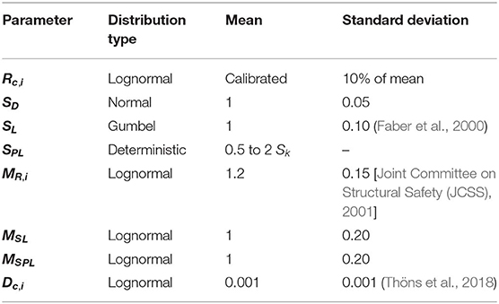
Table 2. Probabilistic Model of structural properties.
In the decision scenario of the testing, the application of the loading is defined as the action available to the decision maker. The choice of the loading level can then be modeled as the set of actions. The choice of different load levels varying from 0.5 to 2 times the characteristic value of the annual maximum live load Sk is considered. The characteristic value Sk is here defined as the load with a probability of non-exceedance of 0.98 in a reference period of 1 year.
Following a successful outcome of the testing, the updated probability of failure of the bridge in any year t is calculated using Bayes' theorem,
It may be expected that the higher the proof load level, the higher would be the updated reliability of the bridge, leading to higher benefit gain from performing the testing but, at the same time, high proof loads may end up damaging the bridge or, worst, cause the bridge to collapse during testing. This is illustrated in Figures 5, 6. The updated annual reliability level of the bridge for the different proof load levels, calculated from Equation 5, is plotted in Figure 5. As a reference, the annual reliability level without any proof loading, calculated using Equation 1, is also plotted. It is observed that load levels higher than 1.0 Sk are needed to demonstrate a reliability level higher than the target reliability level of 4.7. The reliability level of the bridge due to the applied proof load (during the test) is plotted in Figure 6 (refer Equation 4).
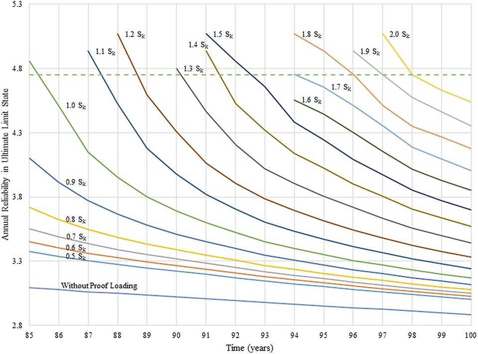
Figure 5. Illustration of the updated annual reliability levels following load testing with the different proof load levels (indicated next to the curves). The annual reliability level without any proof loading is also plotted along with the target annual reliability level of 4.7 (dotted curve).
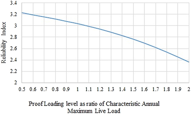
Figure 6. Reliability level of the bridge during testing as a function of the proof load levels.
In the year of performing the proof load test, the bridge may either fail due to the annual maximum live load or due to the proof loading test. The failure probability in the year of testing tPL then is obtained as the union of the events of failure due to test or due to annual maximum live load.
The expected utility is calculated with the aggregation of the expected costs from the structural performance over the remaining service life of the bridge (the costs are modeled as negative utilities). The total expected costs over the remaining service life of the bridge is obtained with the summation of the annual risks. The annual risk of structural failure is computed as the product of the annual probability of failure and the cost incurred as a consequence of failure. In the year of the testing, the risk due to the test performance is taken into account by calculating the annual failure probability according to Equation 6. The consequence of failure is modeled as a cost Cf = 100 monetary units. In computing the total expected costs with the testing, the cost of performing the proof loading test, CPL = 0.1 monetary units, is also added. A depreciation in the modeled costs is considered to discount the future costs to present value, with a discount rate of r = 2%. The calculation of the expected utility without any proof load testing, U0, is presented in Equation 7. The expected utility corresponding to proof load testing with the jth proof load level, U1(SPLj), is calculated using Equation 8.
It may be expected that the higher the proof load level, the higher would be benefit gain from performing the testing on account of the reduced life cycle risks, but, at the same time, high values of the loading also lead to higher risks from the testing. This is clearly observed in Figure 7 where the risks in the year of testing show an upward trend but the updated risks in the year following the testing decrease with increasing proof load levels. Subsequently, the expected benefit gain “U1(SPLj) − U0” shows an increase due to the risk reduction up to a certain level beyond which the risks from the testing cause a drop.
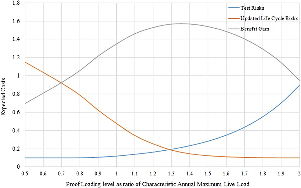
Figure 7. Illustration of expected costs (test risks in blue and life cycle risks in orange) and benefit gain (in gray) from the proof loading as a function of the proof load level.
From the prior decision analysis, it is found that the optimal loading level is 1.3 Sk which leads to the maximum expected benefit gain of 1.56 monetary units (see Figure 7). The updated reliability index with this load level is plotted in Figure 5 and is observed to satisfy the target reliability criteria. Further, with the deterioration model assumed, it is observed (from Figure 5) that the reliability level of the bridge is above the target for up to year 90 of the service life of the bridge. The bridge operator can use this information to schedule repair and maintenance activity.
The decision situation considers the proof load test planner who seeks to identify the optimal strategies for a successful full-scale proof loading test. These include selection of the stop criteria, the optimal method and type of monitoring and the optimal loading level. To achieve this, a pre-posterior decision analysis is performed where the optimal choices are identified with the consideration of yet unknown additional information. The information is acquired from the monitoring system deployed during the proof load testing which measures the structure response to the loading i.e., deformations, strains etc.
The information acquirement leads to knowledge of the realization of the loading model uncertainty related to the load effect i.e., by loading the structure a realization of the model uncertainty is manifested and this can be measured by the monitoring system. Hence, the model uncertainty on the loading is updated,
Here, Umeas is the measurement uncertainty of the monitoring system modeled with a normal distribution and ˆMSPL is the realization of the model uncertainty. The realization of the model uncertainty may be higher or lower than the expected value. A high realization could lead to higher risks of damage to the structure and thereby to the actions of stopping the loading whereas a lower realization could be beneficial as the loading could be continued. Agusta and Thöns (2018) proposed a method for categorizing the realizations of the model uncertainties in connection with target probabilities. Here, the target failure probability for the proof loading is considered as the stop criteria. The value for model uncertainty realization at the threshold ˆMSPL,th is derived using the following:
In the equation above, gfPL, c, i models the ith component's performance in a load testing and P(gfPL,c,i≤0|ˆMSPL,th) is the probability of failure of the ith component during the load testing given that the loading model uncertainty is equal to the threshold value. The outcomes of the structural measurement can be defined in reference to the threshold value as two indication events: event Z1 where the monitoring indicates that the component has adequate performance (i.e., the realization of the loading model uncertainty is lower than the threshold value) and event Z2 where the monitoring indicates that the component has inadequate performance. The target probability of proof loading failure PT(FPL) (or the stop criteria) is treated as a decision parameter to be optimized.
In the following, the loading model uncertainty value at the threshold ˆMSPL,th is derived by modeling the component performance at load level 0.5 Sk and using target probabilities 5·10−3 to 2·10−3 (Equation 10). The indication events are modeled with the distribution of the loading model uncertainty fMSPL(mSPL) and a threshold value corresponding to a target failure probability (Equations 11 and 12).
The expected utility is calculated for each of the stop criteria with consideration of the information and the decision rule that the action of a higher proof loading level is performed only if indication Z1 is obtained. The calculation is inclusive of the costs of monitoring and testing. The monitoring system is modeled with a cost Ci = 0.01 monetary units and precision Umeas ~ N(1, 0.01). Figure 8 illustrates the effect of the indication event Z1, on the reliability during the proof load testing. A risk reduction can be achieved with the information of adequate performance during the proof load testing (indication event Z1). This can be observed in Figure 9 where the expected life cycle costs conditional on the indication event Z1, are plotted.
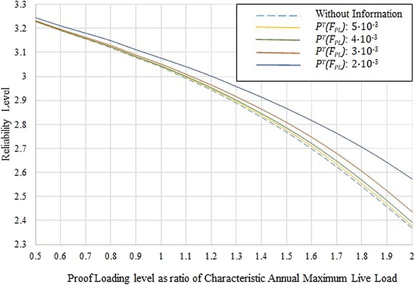
Figure 8. Reliability level of the bridge during testing following indication event Z1 with the different stop criteria (PT(FPL)) used.
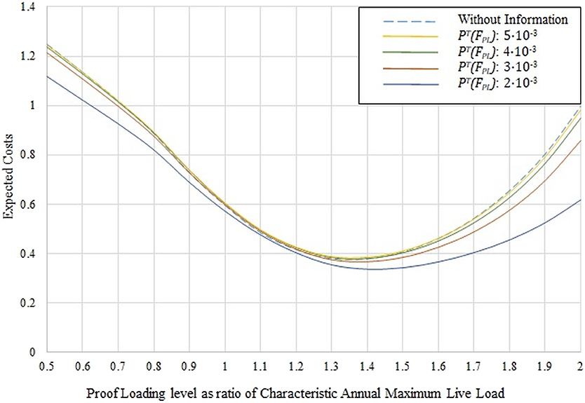
Figure 9. Expected remaining service life costs (inclusive of test risks) as a function of the proof loading level (conditional on indication event Z1).
The Value of Information and Actions is calculated as the difference between the optimal expected utility with proof load testing and monitoring information and the expected optimal utilities without any proof load testing and monitoring. The results are presented in Figure 10 for the different stop criteria considered. It is observed that using the stop criteria with PT(FPL): 3·10-3 leads to the highest expected Value of Information and Actions. The loading level leading to the highest expected utility with this stop criteria is 1.4 Sk.
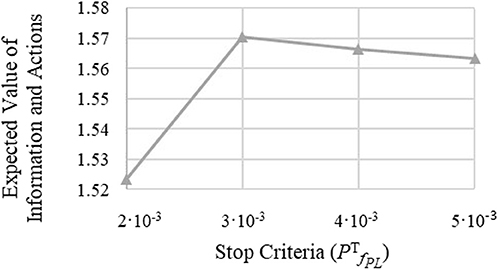
Figure 10. Expected Value of Information and Actions considering the different stop criteria (PT(FPL)) used.
The analysis may be repeated for monitoring systems with different precision and costs to identify the optimal monitoring system, and the associated optimal choices of stop criterion and load level, with the comparison of the expected Value of Information and Actions from different monitoring systems (Kapoor et al., 2019).
For the reclassification of bridges, two decision support approaches have been identified namely (1) for the efficient planning and performance of the proof loading and the prevention of bridge damage and (2) for the identification of an efficient bridge reclassification strategy encompassing proof loading, laboratory testing and advanced modeling and simulation. An exemplary decision analysis has been performed to demonstrate how the optimal proof loading level can be identified and how monitoring based stop criteria may be identified with the utilization of the probabilistic design and decision analysis models.
Both, the decision support approaches and the exemplary decision analysis constitute a first step and will be further substantiated and further developed to align the decision scenarios and the structural and structural information modeling to specific bridges and the specific bridge integrity management processes. One of the challenges related to the decision analyses seem to relate to the precision of the theoretical model related to the structural behavior. It seems to be a precondition that there are a number of unknown contributions to the actual capacity of the structure that cannot be sufficiently modeled analytically. A reduction in the uncertainties related to the models is achieved when applying proof loading. If, however, an extremely accurate model for the capacity is used as a basis, proof loading may not serve as an efficient means for the reclassification. It therefore seems important to provide the information interaction between the disciplines described in Figure 3. However, we cannot abstain from using the basis theoretical model, because we need to use a model of the structural behavior in order to determine the critical failure mode and the critical load configuration. This is why the illustration in Figure 3, which indicates that there is an important information interaction back and forth between all the three different disciplines.
This paper summarizes recent challenges advances in proof loading of bridges and introduces an approach of the systematic reclassification of bridges. The development of a full-scale test method is described in detail addressing the demands of a high loading magnitude combined with a fast and precise load application.
The systematic and network wise reclassification of bridges maybe achieved by a combination of methods, approaches and technologies with directed research. This includes the further development of (1) modeling and simulation techniques, (2) of tailored testing strategies in combination with monitoring, and (3) probabilistic and decision analyses to combine modeling, testing and performance information and to identify efficient strategies for reclassification.
All datasets generated/analyzed for this study are included in the article/supplementary material.
All authors have agreed on the content of this paper. Consequently, it includes a result of the author's discussions and portions of their expertise in the paper sections. However, ST, MK, SE, and JDS have worked mostly on the probabilistic part with ongoing discussions with JWS who have worked on the remaining parts (i.e., testing, systematic re-classification etc.) with assistance from CC. However, it is difficult to separate the contributions sharply, which has not been the scope of the collaborating authors.
The authors declare that the research was conducted in the absence of any commercial or financial relationships that could be construed as a potential conflict of interest.
The financial support and assistance from the Danish Road Directorate, is greatly acknowledged as well as their support and commitment.
AASHTO (2011). The Manual for Bridge Evaluation. Washington, DC: American Association of State Highway and Transportation Officials.
ACI Committee 437 (2013). Code Requirements for Load Testing of Existing Concrete Structures (ACI 437.2M-13). Farmington Hills, MA: ACI Committee 437.
Agusta, A., and Thöns, S. (2018). “Structural monitoring and inspection modeling for structural system updating,” in Sixth International Symposium on Life-Cycle Civil Engineering (Ghent).
Alkhrdaji, T., Barker, M., Chen, G., Mu, H., Nanni, A., and Yang, X., (2001). “Destructive and non-destructive testing of bridge J857,” in Strengthening and Testing to Failure of Bridge Decks, Vol. 1 (Phelps County, MO: Center for Infrastructure Engineering Studies), 1–131.
Benjamin, J. R., and Cornell, C. A. (1970). Probability, Statistics and Decision for Civil Engineers. New York, NY: McGraw-Hill Book Company.
Brüske, H., and Thöns, S. (2016). “Value of information by updating of model uncertainties utilising proof loading in the context of series and Daniels systems,” in Proceedings of the International RILEM Conference Materials, Systems and Structures in Civil Engineering (Lyngby), 52–61.
Casas, J. R., and Gómez, J. D. (2013). Load rating of highway bridges by proof-loading. KSCE J. Civil Eng. 17, 556–567. doi: 10.1007/s12205-013-0007-8
Civil Engineering Review. (1952). Destruction of the Prestressed Concrete Footbridge at the South Bank. 6, 33.
DAfStb (2000). DAfStb-Guideline: Load Tests on Concrete Structures. Berlin: Deutscher Ausschuss für Stahlbeton.
Daniels, H. E. (1945). “The statistical theory of the strength of bundles of threads,” in Proceedings of the Royal Society of London. Series A, Mathematical and Physical Sciences, Vol. 183, 405–435. Available online at: http://www.jstor.org/stable/97823 (accessed January 13, 2017).
Diamantidis, D. (1987). Reliability assessment of existing structures. Eng. Struct. 9, 177–182. doi: 10.1016/0141-0296(87)90013-7
Ditlevsen, O., and Madsen, H. O. (2005). Structural Reliability Methods. Available online at: http://www.mek.dtu.dk/staff/od/books.htm (accessed January 17, 2017).
Elmont, V. J. (1913). “Test-loading until breaking point of a 100-foot arch bridge,” in Canadian Engineer.
Ersdal, G., Sørensen, J. D., and Langen, I. (2003). “Updating of structural failure probability based on experienced wave loading,” in International Offshore and Polar Engineering Conference, Vol. 5 (Honolulu, HI), 461–468.
Faber, M. H., Val, D. V., and Stewart, M. G. (2000). Proof load testing for bridge assessment and upgrading. Eng. Struct. 22, 1677–1689. doi: 10.1016/S0141-0296(99)00111-X
Fu, G., and Tang, J. (1995). Risk-based proof-load requirements for bridge evaluation. J. Struct. Eng. 121, 542–556. doi: 10.1061/(ASCE)0733-9445(1995)121:3(542)
Goodpasture, D. W., and Burdette, E. G. (1973). Full scale tests to failure of four highway bridges. Am. Railway Eng. Assoc. 74, 454–473.
Gosbell, K. B., and Stevens, L. K. (1968). Test loading of a full scale bridge. ARRB Proc. 4, 2018–2041.
Gutermann, M., and Schröder, C. (2015). Loading vehicle BELFA development and experience gained in 10 years of practice. Bridge Struct. 11, 19–31. doi: 10.3233/BRS-150081
Halding, P. S., Schmidt, J. W., Jensen, T. W., and Henriksen, A. H. (2017). “Structural response of full-scale concrete bridges subjected to high load magnitudes,” in 4th Conference on Smart Monitoring, Assessment and Rehabilitation of Civil Structures (Zürich).
ICE (1998). Guidelines for the Supplementary Load Testing of Bridges. London: The Institution of Civil Engineers - National Steering Committee for the Load Testing of Bridges.
Joint Committee on Structural Safety (JCSS) (2001). Probabilistic Model Code. Joint Committee on Structural Safety (JCSS)
Jorgenson, J. L., and Larson, W. (1976). Field testing of a reinforced concrete highway bridge to collapse. Transport. Res. Rec. 66–71.
Kapoor, M., Schmidt, J. W., Sorensen, J. D., and Thöns, S. (2019). “A decision theoretic approach towards planning of proof load tests,” in 13th International Conference on Applications of Statistics and Probability in Civil Engineering (ICASP13) (Seoul), 1715–1722.
Lantsoght, E. O. L. (2013). Shear in reinforced concrete slabs under concentrated loads close to supports. ACI Struct. J. 110, 275–284.
Lantsoght, E. O. L., Veen, C. V. D., Boer, A. D., and Hordijk, D. A. (2017). “Proof load testing of reinforced concrete slab bridges in the Netherlands,” in 96th Annual Meeting of the Transportation Research Board (Washington, DC).
Lantsoght, E. O. L., Yang, Y., Tersteeg, R. H. D., Van Der Veen, C., and De Boer, A. (2016). “Development of stop criteria for proof loading,” in Life-Cycle of Engineering Systems: Emphasis on Sustainable Civil Infrastructure, eds J. Bakker, D. M. Frangopol, and K. van Breugel (Delft: Taylor & Francis), 1064–1071.
Lantsoght, E. O. L., Yang, Y., Van Der Veen, C., and Hordijk, D. A. (2018). “Stop criteria for proof load tests verified with field and laboratory testing of the Ruytenschildt Bridge Ruytenschildt field test,” in IABSE Conference (Copenhagen), 1–8.
Lin, T. S., and Nowak, A. S. (1984). Proof loading and structural reliability. Reliabil. Eng. 8, 85–100.
Nanni, A., Alkhrdaji, T., Chen, G., Barker, M., Yang, X., and Mayo, R. (1999). “Overview of testing to failure of a highway bridge strengthened with FRP composites,” in 4th International Symposium on FRP for Reinforcement of Concrete Structures (FRPRCS4) (Baltimore, MD), 69–80.
Nishijima, K., and Faber, M. H. (2007). Bayesian approach to proof loading of quasi-identical multi-components structural systems. Civil Eng. Environ. Syst. 24, 111–121. doi: 10.1080/10286600601159172
Rackwitz, R., and Schrupp, K. (1985). Quality control, proof testing and structural reliability. Struct. Safety 2, 239–244. doi: 10.1016/0167-4730(85)90030-X
Raiffa, H., and Schalifer, R. (1961). Applied Statistical Decision Theory. Boston, MA: Harvard University Press.
Rösli, A. (1963). Die Versuche an der Glattbrücke in Opfikon. Eidgenössische Materialprüfungs- und Versuchsanstalt für Industrie, Bauwesen und Gewerbe, 192, 85.
Saraf, V., and Nowak, A. S. (1998). Proof load testing of deteriorated steel girder bridges. J. Bridge Eng. 3, 82–89. doi: 10.1061/(ASCE)1084-0702(1998)3:2(82)
Schmidt, J. W., Halding, P. S., Jensen, T. W., and Engelund, S. (2018). High magnitude loading of concrete bridges. ACI Struct. J. 323, 9.1–9.20.
Sørensen, J. D., and Toft, H. S. (2010). Probabilistic design of wind turbines. Energies 3, 241–257. doi: 10.3390/en3020241
Thöns, S. (2018). On the value of monitoring information for the structural integrity and risk management. Comp. Aided Civil Infrastruct. Eng. 33, 79–94. doi: 10.1111/mice.12332
Thöns, S., Döhler, M., and Long, L. (2018). On damage detection system information for structural systems. Struct. Eng. Int. 28, 255–268. doi: 10.1080/10168664.2018.1459222
Thöns, S., Faber, M. H., and Rücker, W. (2011). “On the utilization of monitoring data in an ultimate limit state reliability analysis,” in 11th International Conference on Applications of Statistics and Probability in Civil Engineering (ICASP) (Zurich).
Von Neumann and Morgenstern (1947). Theory of Games and Economical Behavior. Princeton, NJ: Princeton University Press.
Yang, J. N. (1976). Reliability analysis of structures under periodic proof tests in service. AIAA J. 14, 1225–1234. doi: 10.2514/3.7214
Zhang, J., Peng, H., and Cai, C. S. (2011). Field study of overload behavior of an existing reinforced concrete bridge under simulated vehicle loads. J. Bridge Eng. 16, 226–237. doi: 10.1061/(ASCE)BE.1943-5592.0000140
Keywords: load testing, bridge reclassification, decision analysis, probabilistic analysis, bridges
Citation: Schmidt JW, Thöns S, Kapoor M, Christensen CO, Engelund S and Sørensen JD (2020) Challenges Related to Probabilistic Decision Analysis for Bridge Testing and Reclassification. Front. Built Environ. 6:14. doi: 10.3389/fbuil.2020.00014
Received: 15 December 2018; Accepted: 04 February 2020;
Published: 28 February 2020.
Edited by:
Emilio Bastidas-Arteaga, Université de Nantes, FranceReviewed by:
Luca Sgambi, Catholic University of Louvain, BelgiumCopyright © 2020 Schmidt, Thöns, Kapoor, Christensen, Engelund and Sørensen. This is an open-access article distributed under the terms of the Creative Commons Attribution License (CC BY). The use, distribution or reproduction in other forums is permitted, provided the original author(s) and the copyright owner(s) are credited and that the original publication in this journal is cited, in accordance with accepted academic practice. No use, distribution or reproduction is permitted which does not comply with these terms.
*Correspondence: Jacob Wittrup Schmidt, andzQGJ5Zy5kdHUuZGs=
Disclaimer: All claims expressed in this article are solely those of the authors and do not necessarily represent those of their affiliated organizations, or those of the publisher, the editors and the reviewers. Any product that may be evaluated in this article or claim that may be made by its manufacturer is not guaranteed or endorsed by the publisher.
Research integrity at Frontiers
Learn more about the work of our research integrity team to safeguard the quality of each article we publish.