 Nicolò Simoncello
 Paolo Zampieri
 Jaime Gonzalez-Libreros
 Simone Perboni
- Department of Civil, Environmental and Architectural Engineering, University of Padua, Padua, Italy
Historical masonry arch bridges are a fundamental part of the road and railway networks in Europe. Very often, due to factors such as lack of maintenance, increase of traffic loads, etc., these structures need interventions in order to guarantee their adequate structural performance. For this reason, an important research effort has been devoted in previous decades to study the behavior of masonry arches and to identify innovative techniques able to increase their ultimate capacity, such as fiber reinforced polymer (FRP) composites. In this paper, the results of an experimental campaign carried out on masonry arches strengthened with one FRP layer applied at the structure intrados are used to calibrate a numerical analysis model. Then, the model is used to predict the contribution that this type of strengthening would have had on the well-known Prestwood Bridge. The numerical results show that the hypothetical intervention of the Prestwood Bridge would imply an increase in the ultimate load of the structure, although it would be significantly lower than that usually obtained for the case of arches tested in laboratory.
Introduction
Masonry bridges in service within the railway and road lines worldwide are a significant part of the infrastructure heritage, mainly in Europe (Melbourne et al., 2007). Most of these bridges were built more than 100 years ago and have been, consequently, subjected to environmental chemical and physical actions, seismic events, increase in the traffic loads, etc. (Modena et al., 2015). For these reasons, the conservation, maintenance, and continuous operation of masonry bridges are a current challenge for transport infrastructure managers.
The starting point of any maintenance intervention on masonry bridges consists on the evaluation of their load-carrying capacity, and seismic resistance for the actual state of conservation and operating conditions. With this need in mind, in recent years, different calculation methods and guidelines (e.g., UIC guideline)1 for the evaluation of the ultimate (ULS) and serviceability limit states (SLS) of masonry bridges have been developed. Among the available methods for the structural analysis of masonry bridges, it is possible to find: simplified methods (Zhang et al., 2018), numerical method for assess the seismic capacity (Pelà et al., 2013; Zampieri et al., 2014, 2015a,b; Sarhosis et al., 2016; Mahmoudi Moazam et al., 2018; Marefat et al., 2019), methods based on the limit analysis (Basilio et al., 2014; Chiozzi et al., 2017; Bertolesi et al., 2018), analysis strategies able to take into account the settlement of the supports (Galassi et al., 2018a,b; Zampieri et al., 2018a,b, 2019) or geometry uncertainties (Cavalagli et al., 2017), macro-element models (Cannizzaro et al., 2018; D'Altri et al., 2019), and methods based on finite element modeling (FEM) (Brencich and Sabia, 2008; Costa et al., 2016; Scozzese et al., 2019), discrete element modeling (DEM) (Sarhosis et al., 2016, 2019; Forgács et al., 2017, 2018; Stockdale et al., 2019) or a combination of both (Milani and Lourenço, 2012).
A possible outcome of the initial masonry bridge capacity assessment is the need of a strengthening intervention. At this point, it will be required to select the most appropriate intervention technique, among the several possibilities available nowadays (Modena et al., 2015). Such decision depends on performance and strength targets and the restrictions that can arise during the execution of the strengthening. For instance, when the intervention must be carried out without interruption of the traffic on the bridge, the use of fiber reinforced polymer (FRP) composites, applied on the arch intrados, can provide a satisfactory increase in the arch strength (Oliveira et al., 2010). Due to the high tensile strength of the FRP, the formation of collapse hinges is postponed when compared to an unreinforced arch bridge in ultimate load conditions (Oliveira et al., 2010). Furthermore, the application of FRP does not substantially modify the mass and stiffness of the structure (Bertolesi et al., 2018), but does not improve the performance of the bridge for serviceability limit states (Modena et al., 2015).
In this paper, a non-linear continuum model for the analysis of masonry arches strengthened with FRP composites is presented, with the aim of providing numerical tools for the theoretical evaluation of the capacity of FRP-strengthened masonry bridges. As a first step, a finite element model, calibrated based on the experimental results found in Borri et al. (2011), is developed to evaluate the ultimate strength of an FRP-strengthened masonry arch tested in laboratory conditions. The model considers the bond-slip law at the FRP-masonry interface provided by the CNR-DT 200 R1/20132 and a non-linear stress-strain behavior for the masonry. Then, the model is extended for the case of the single-span Prestwood bridge, tested to collapse more than 30 years ago (Page, 1987; Cavicchi and Gambarotta, 2005, 2006, 2007; Sarhosis et al., 2019). Available experimental data from the original test and the results of the numerical models of the laboratory tested arches are used to predict the increase in strength provided by a hypothetical intervention of this structure by means of FRP. In this way, the numerical analysis is validated by combining not only the experimental information obtained under laboratory conditions but also that found during the testing of a real scale masonry arch. It is expected that the proposed methodology will be used for the development of future numerical models able to simulate the behavior and predict the load capacity of real scale FRP-strengthened masonry arches.
Material Modeling
The structural analysis of the masonry arch bridges is performed using the finite element software DIANA (DIANA FEA BV)3 through a continuum model of the masonry with a non-linear tension and compression stress-strain relationships called “Total Strain Crack Model” (TSCM), as shown in Figure 1. The TSCM provides reliable results when used for the modeling of quasi-brittle materials (such as masonry and concrete) as it allows capturing the phenomena of cracking and crushing of the materials.
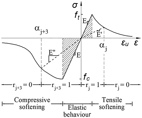
Figure 1. Stress-strain diagrams (TSCM).
The TCSM allows to take into account the material deterioration (both in compression and in tension) with the definition of six internal variables (αk) where k = 1,2,.,2n (where n is the number of strain components). Internal variables k = 1,…,n monitoring the maximum strain, hence greater or equal than zero, and variables k = n+1,…, 2 × n monitoring minimum strain and hence smaller or equal than zero (Figure 1; n is the number of strain components). It is assumed that damage recovery is not possible which implies that the absolute values of the internal damage variables are increasing.
The loading–unloading–reloading condition is monitored with the additional unloading constraints (rk) which are determined for both tension and compression to model the stiffness degradation in tension and compression separately.
Constitutive Laws
The relationship between the cracking stress (σnn) and the cracking strain (εnn), in the normal direction respect to the crack, can be defined as:
Where:
-ft is the tensile strength;
-εnn, u is the ultimate tensile strain.
The function describes the type of softening model used. If the softening behavior is related to Mode-I, the fracture energy can be written as:
Where h is the equivalent length of the element.
Linear Tension Softening
For the case of masonry in tension, the stress can be defined by means of a linear tension softening relationship (see Figure 2A):
The factor α, considering the ultimate strain at cracking, can be written as:
When the ultimate strain is reached, i.e., εnn = εnn, u:
And the tensile strength will be equal to:
where E is the initial Young modulus of the material.
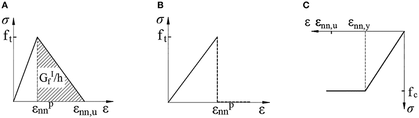
Figure 2. Stress-strain behavior for: (A) tensile linear softening; (B) tensile brittle; (C) compression constant.
Brittle Tension
For the case of brittle tensile behavior (see Figure 2B), after the elastic limit is reached, the stress at the next step is equal to zero and there is no longer tensile strength in the material. This relationship is used to describe the behavior of FRP in tension.
Elastic-Perfectly Plastic Compression
For compression, the masonry is modeled using a function that considers the crushing of the material. The compressive behavior shows a dependence between strength and ductility which increases with the increase of the isotropic stress. For the model, once the maximum compressive strength of the material is reached, the compressive stress remains constant with the increase of the strain (see Figure 2C).
Masonry-FRP Bond-Slip Behavior
Debonding of FRP from masonry substrates is generally associated with Mode-I or Mode-II fracture failure modes. However, for the cases analyzed in this paper, it is assumed that spike anchors, designed to absorb the normal tensile stresses between the composite and the masonry substrate, were used as part of the strengthening strategy and therefore, Mode-I is not taken into account in the numerical analysis. Failure Mode-II is considered through the bond-slip relationship shown in Figure 3, which models the bond behavior between the FRP and the masonry substrate.
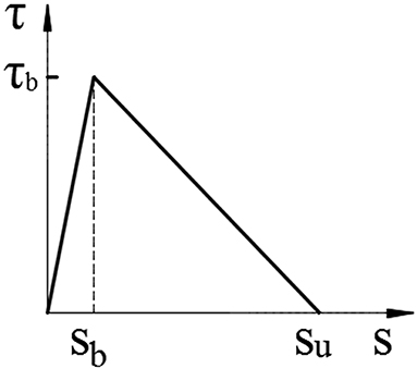
Figure 3. Bond-slip relation between composite and masonry substrate.
This bond-slip model used a constitutive law based on the “Total Deformation Theory” (Vecchio and Collins, 1986). This theory expresses the tension as a function of the relative tangential displacement (s) between the two materials. The function used to describe the relationship between normal tension (tn) and the relative displacement (Δun) is linear, while the relationship between the tangential stress (τ) and the relative tangential displacement is assumed to be non-linear as described by the following relations:
Where kn is the normal stiffness.
It is possible to describe the tangential stiffness as the partial derivative of the tangential force (τ) with respect to the relative tangential displacement (s). Therefore, the tangential stiffness matrix will be composed of the following terms:
Material Behavior Definition for the Model
The tensile and compression behavior of the masonry are defined by means of two stress-strain relationships. For compression, an elastic-perfectly-plastic behavior is considered, while for tension, an elastic law with linear softening (finite fracture energy value) is used. The tensile behavior of the FRP, is modeled considering an elastic-linear behavior with finite strength.
The bond between the FRP and the masonry substrate is defined with a bilinear bond-slip law defined by the CNR-DT 200 R1/2013 based on the characteristics of the masonry substrate. The maximum tangential bond stress can be expressed as follows:
Where ΓF is the fracture energy of the post-elastic branch and su is the ultimate slip.
The angular coefficient of the ascending linear branch (K1) is defined with Equation (11), where Ga and Gm are, respectively, the tangential elasticity module of the adhesive and the masonry block, while ta is the nominal thickness of the adhesive and tm lo thickness of the masonry block that participates in the deformability of the interface. The coefficient c1 ranges between 0.5 and 0.7.
The fracture energy (ΓF) of the post-elastic branch is defined by Equation (12), where kb is a corrective coefficient of geometric type defined by Equation (13). The coefficient kg is defined by experimental tests and is defined equal to 0.093 mm for the case of brick masonry. The values fcm and ftm are the average compressive and tension strengths of the masonry, respectively.
The ultimate slip (su) is assumed equal to 0.4 mm for clay brick masonry according to CNR-DT 200 R1/2013.
Model Calibration
In this section, numerical models for one unstrengthened and one FRP-strengthened masonry arch are calibrated based on the experimental tests carried out by Borri et al. (2011) on specimens subjected to a mid-span concentrated load. The arches are made of a single row of clay brick with a span L of 2,000 mm and an arch rise f equal to 1,000 mm (Figure 4A). The thickness of the arch is 125 mm while the depth is 250 mm. For the strengthening, one 100 mm width FRP layer and spike anchors were applied at the arch intrados (see Figure 4B).
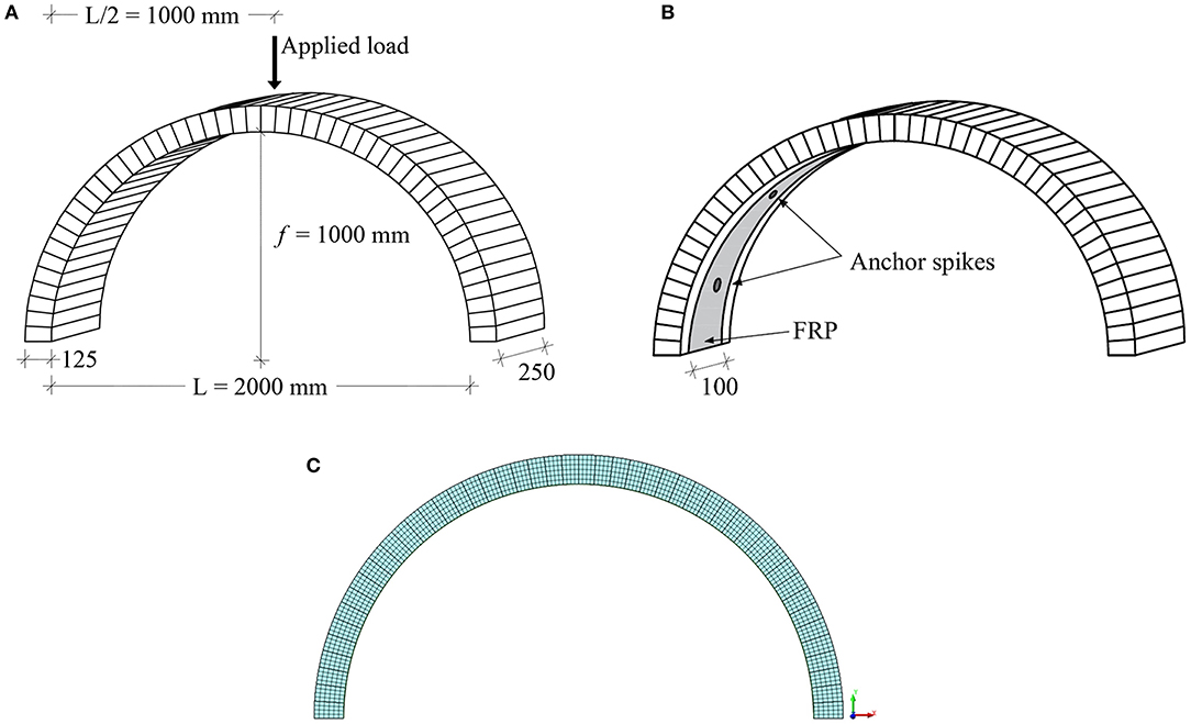
Figure 4. (A) Geometrical properties of the masonry arches tested by Borri et al. (2011); (B) FRP strengthening configuration according to Borri et al. (2011); (C) Mesh adopted for the finite element analysis.
The density, compressive (fc) and tensile (ft), elastic modulus (E) of the bricks and mortar used by Borri et al. (2011), are reported in Table 1.
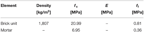
Table 1. Brick units and mortar mechanical properties (Borri et al., 2011).
The masonry compressive strength (fk) and elastic modulus (Em) of the masonry were calculated according to the Eurocode 64, using Equations (14) and (15):
Where the coefficient K, the mortar compressive strength (fm) and the compressive strength of the brick (fb) are assumed 0.44, 6.95, and 20.99 MPa, respectively. Considering that the tensile strength of the masonry (fctm) was not available, four non-linear analyses were performed in order to determine a value of fctm compatible with the experimental available evidence. For the masonry, Table 3 includes the values of the density, fk, Em, type of constitutive law in compression and tension, Gt, and thickness (t) used in the model. Table 2 also includes values of elastic modulus, ultimate tensile strength, and thickness of the FRP layer. As expressed before, the bond-slip law for FRP and masonry substrate interface proposed by the CNR-DT 200 R1/2013 is used for the development of the numerical models. Considering an FRP width equal to 100 mm, with the FRP mechanical properties reported in Table 2, it is possible to determine the parameters of the bond-slip law shown in Table 3.
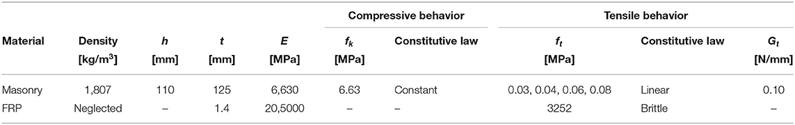
Table 2. Masonry and FRP mechanical properties.
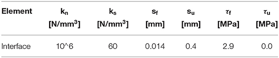
Table 3. Bond-slip constitutive law parameters.
The FE model consists of 2D plane strain elements (Figure 4C). The quadratic interpolation and Gauss integration type was adopted for the eight node quadrilateral isoperimetric strain elements. The thickness of the arch was divided into 6 elements for a total of 1,152 elements. The boundary conditions were applied by restraining the nodes of the elements located at the left and right extremes of the arch. The load was applied by means of a displacement at the node located at the arch crow with 50 steps increment. For the analysis, non-linear material and non-linear geometry were considered. The iteration type for the iteration scheme was a Newton Raphson algorithm with 0.01 energy norm.
Unstrengthened Masonry Arch
The mechanical parameters used for the analysis of the unstrengthened arch are shown in the first row of Table 3. The load-arch crown displacement curves obtained from the numerical analyzes of the unstrengthened arch (N.A._U), considering four different values of masonry tensile strength (0.03, 0.04, 0.06, and 0.08 MPa), were compared with the maximum load (Fmax=0.70 kN) and corresponding displacement value (dFMax=1.50 mm) recorded experimentally by Borri et al. (2011), as shown in Figure 5. Results show that the numerical analysis with fctm=0.03 MPa gives the better agreement with the experimental data in terms of Fmax. However, that model highly underestimates the corresponding value of dFmax as the predicted value is equal to 0.24 mm (around six times lower than the experimental one). It is also possible to see that fctm has an almost proportional influence on the maximum load predicted by the remaining models. Values of dFmax seem to be not related with the masonry tensile strength, as results of this parameter for models with fctm equal to 0.04, 0.06, and 0.08 MPa are similar.
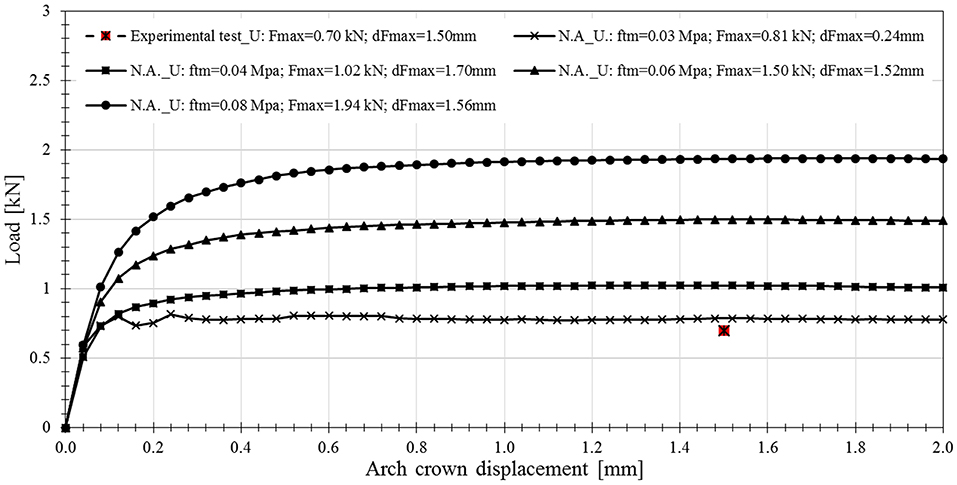
Figure 5. Numerical Load—Arch crown displacement curves for the unstrengthened arch.
FRP-Strengthened Masonry Arch
Experimental and numerical load-arch crown displacement curves for the FRP-strengthened arch are shown in Figure 6A. As expressed above, the experimental arch was strengthened using s spike anchors aimed to prevent the debonding of the FRP layer from the masonry substrate. It is highlighted that the experimental curve presented in Figure 6A is a discrete approximation of the curve found in Borri et al. (2011), as all the points in the graph were not available.
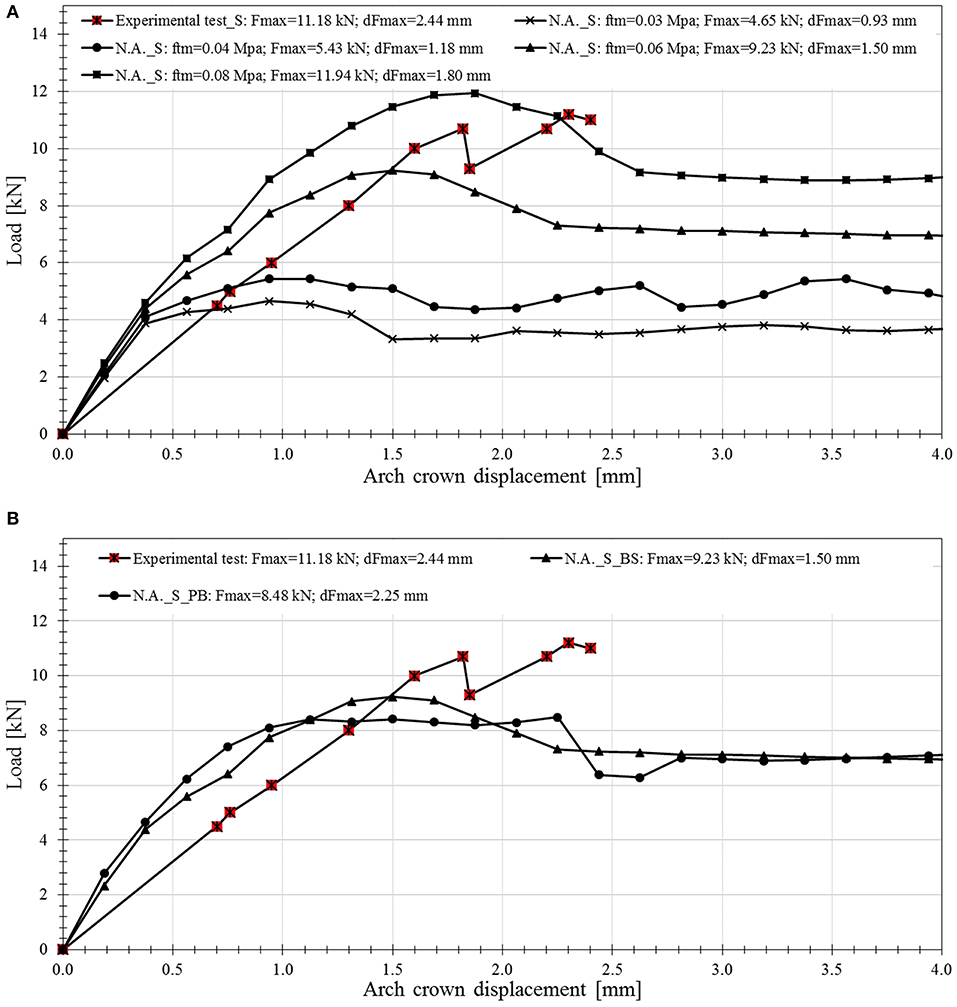
Figure 6. Experimental and numerical Load-Arch crown displacement curves for the FRP-strengthened arch: (A) with ftm= 0.03, 0.04, 0.06, and 0.08 MPa; (B) with ftm = 0.06 MPa, and with (N.A._S_BS) and without (N.A._S_PB) perfect masonry-FRP bond.
In Figure 6A, it is possible to observe that the numerical analysis of the strengthened arch (N.A._S) with a value of ftm equal to 0.08 MPa is the closest to the experimental test in terms of Fmax and dFmax. However, it considered that numerical analysis with ftm= 0.06 MPa, appropriately conservative results in good agreement with the experimental evidence. It is also highlighted that the difference in the value of ftm that predicts better results for the unstrengthened (ftm = 0.03 MPa) and strengthened (ftm = 0.06 or 0.08 MPa) conditions might be attributed to a random distribution of the tensile strength that cannot be controlled during the construction of the specimens.
In Figure 6B, the finite element analysis performed with the use of the bond-slip law at the FRP and masonry interface and a tensile strength of 0.06 MPa (NM_S_BS in Figure 6B) is compared with an analysis assuming perfect bond between the masonry substrate and the FRP layer (NM_S_PB in Figure 6B). For the latter case, the maximum tensile strength of the FRP was limited to that obtained for an effective bonded length of 100 mm and a maximum tangential stress of 2.9 MPa (i.e., 207 MPa). Results show that the curves obtained numerically are practically the same, although both underestimate the experimental Fmax. For this case, this result suggests that a simplification of the numerical analysis assuming perfect bond provides similar results than that of a model that uses a more refined FRP-masonry bond interface law. Therefore, such simplified model might be used for a fast and preliminary evaluation of the increase in strength provided by the FRP strengthening, as long as the maximum tensile force in the composite is limited to a value based on the bond strength at the masonry-FRP interface.
Masonry Arch Bridge: Prestwood Bridge
The FEM calibration carried out in the previous section is extended to the case of the well-known Prestwood bridge, for which experimental data from a destructive test is available (see Figure 7A). First, using the ultimate experimental load and previous numerical analyzes developed by other authors (Cavicchi and Gambarotta, 2005; Sarhosis et al., 2019) a FEM of the original structure, was performed. Subsequently, a second model, in which a layer of FRP is applied at the arch intrados, was developed using the analysis strategy and the bond-slip law previously calibrated.
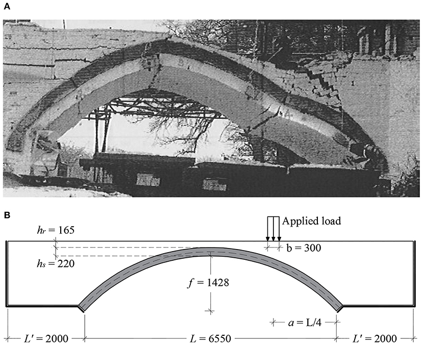
Figure 7. Prestwood bridge (A) collapse; (B) geometrical properties.
The Prestwood bridge is a single-sided masonry bridge with a span L = 6,550 mm, arch rise f = 1,428 mm, width s = 3,800 mm and thickness t = 220 mm (see Figure 7B). The mechanical properties of the materials and used for the FEM of the bridge are shown in Table 4.

Table 4. Prestwood bridge: material mechanical properties.
As before, masonry was modeled with using the TSCM stress-strain relationship (see Figure 1). The filling was modeled using 2D finite elements considering a perfectly plastic elastic constitutive law with a Mohr-Coulomb failure criterion (see Table 4).
The bridge was tested in situ by applying a distributed load over a 300 mm long section over the entire thickness of the arch at one quarter of the span (see Figure 7B). The load was applied in the model through a 300 × 3,800 mm rigid zone. The numerical model and the mesh discretization are shown in Figure 8A. The numerical analysis, the iteration type and the iteration scheme are the same defined for the numerical analysis of the arch tested by Borri et al. (2011) (see section Model Calibration) but in this case, 100 steps of displacement increment were required.
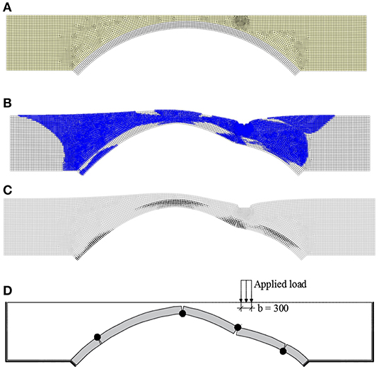
Figure 8. (A) Model mesh discretization; (B) plastic zones contour at ultimate load; (C) cracking pattern contour at ultimate load condition; (D) Prestwood bridge: Experimental collapse mechanism.
Unstrengthened Bridge
The results of the numerical analysis of the Prestwood bridge (unstrengthened bridge, NA_US) are presented in this section. Figures 8B,C show the plastic zones location cracking pattern contour obtained from the model at ultimate load condition, respectively. Results show that the collapse mechanism and plastic hinge location are in good agreement with the available experimental results shown in Figures 7A, 8D.
As pointed out by other authors (Cavicchi and Gambarotta, 2005), Figure 8B shows that the filling, in addition to act as a permanent load applied to the arch, provides the structure with an additional strength that cannot be neglected.
Figure 9 shows the load-arch control displacement point curve for the unstrengthened condition obtained from the numerical analysis. The arch control displacement point corresponds to the node located at the middle of the arch thickness underneath the center of application of the load. Figure 9 also includes the value of maximum applied load obtained from the measurements on site (228 kN) (Page, 1987). As seen in Figure 9, the maximum applied load predicted by the numerical analysis (245 kN) is in good agreement with the experimental one, which validates the FEM.
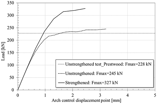
Figure 9. Numerical Load-Arch displacement control point curve (unstrengthened and strengthened conditions) and experimental maximum applied load (unstrengthened condition) for Prestwood bridge (Page, 1987).
Strengthened Bridge
This section presents the results of the numerical analysis aimed to predict the contribution of the application of an FRP layer to the Prestwood bridge strength. The model was developed using the numerical analysis strategy shown in Model Calibration for the modeling of the experimental tests conducted by Borri et al. (2011). The masonry-FRP interface was modeled by means of the bilinear bond-slip law proposed by the CNR-DT 200 R1/2013 with the parameters shown in Table 5. The FRP strengthening consist in one layer of the composite applied to the entire surface of the intrados of the bridge, shown in Figure 10A. The mechanical and properties of the FRP composite can be found in Table 3.

Table 5. Prestwood bridge model: bond-slip constitutive law parameters.
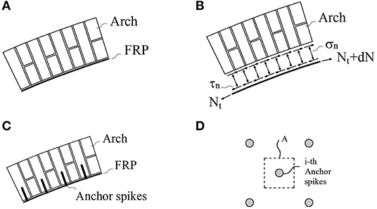
Figure 10. (A) Arch FRP strengthening, (B) normal and tangential stress distribution between FRP and masonry substrate, (C) lateral view of spike anchors, (D) influence area of the i-th spike anchor.
Due to the curved surface of the arch, the tensile force Nt on the FRP requires the development of tangential stresses (τn), and normal tensile stresses (σn) at the masonry-FRP interface for the system to be in equilibrium (see Figures 10A,B).
The numerical model was developed considering that the tangential stresses (see Figure 10B) are resisted by the bond strength at the FRP-masonry interface. In addition, it was assumed that the normal tensile stresses (σn) are resisted by anchors placed at the arch intrados (see Figures 10C–D). Under this consideration, the force acting in each anchor (Fc), for a given area of the strengthening (A), is equal to:
Figure 9 shows the numerical load-arch control displacement point curve for the strengthened condition. It is possible to observe that the presence of the FRP layer provides an increase in peak load of 43 and 33% with respect to the unstrengthened experimental and numerical peak applied loads. It is worth noticing that the peak load was defined as the condition for which the ultimate strain of the masonry in compression or the FRP in tension is reached. For this case, this condition is attained due to crushing of the masonry. For this reason, the FRP material is not fully exploited and the stress developed in the composite at ultimate conditions is about 60% of the stress that could developed under debonding conditions (τf = 1.1 MPa). When results in Figures 5, 6, 9 are compared, the increase provided by the strengthening is significantly lower for the Prestwood bridge than for the arch tested by Borri et al. (2011). This result can be explained by the presence of the infill and the lower material properties of the masonry of the Prestwood bridge.
Figure 9 also shows that the presence of the FRP layer does not influence the initial stiffness of the strengthened bridge when compared to the unstrengthened condition. However, the value of displacement at peak load for the strengthened condition (2.42 mm) is lower than that obtained from the unstrengthened model (3.44 mm). This result implies that in addition to an increase in the peak load, the FRP system provides a reduction in the corresponding displacement when compared to unstrengthened conditions.
Conclusions
In this paper, a numerical analysis procedure to evaluate the structural performance of FRP-strengthened masonry arches was calibrated based on experimental evidence found in the available literature. Then, this method was extended to the well-known Prestwood bridge in order to evaluate the possible increase in strength provided by an eventual intervention by means of FRP applied at the arch intrados. The main conclusions that can be drawn from this study are:
• For both unstrengthened and strengthened conditions, the value of mean tensile strength of the masonry plays a crucial role on the overall structural performance of the arches. Numerical results show that higher values of maximum load attained by the arches are expected for higher values of masonry tensile strength. However, the value of the displacement associated to the maximum load seems to be independent of the tensile strength.
• Different values of mean tensile strength for the unstrengthened and strengthened conditions were required to calibrate the numerical models performed in this study, although the experimental data was taken from arches constructed and tested under the same laboratory conditions. These results suggest that even under such ideal conditions, it is possible to find a significant dispersion in the values of the mechanical properties of the materials, that might affect significantly the overall structural performance of the specimens.
• A simplification of the numerical analysis that assumes perfect bond between the masonry and the FRP composite instead of the use of a bond-slip law at the matrix-FRP interface might provide reliable results as long as the maximum tensile strength in the composite is limited to that would be attained under debonding conditions.
• The increase in strength provided by the application of an FRP layer to the intrados of the arch of a real bridge analyzed in this paper with respect arches tested under laboratory conditions is lower. The reduction in the effectiveness of the strengthening can be attributed to the following reasons: (i) The scale factor between the arch size and the area of FRP applied for the specimens tested in the laboratory are not similar to those found in real bridges; (ii) The presence of the filling material (not found in most experimental tests) increases the normal stress acting in the arch and consequently reduces the beneficial effect of the strengthening; (iii) Mechanical properties of the masonry in real bridges might be generally lower than those used in laboratory, due to the age of construction and conservation state.
The above conclusions were drawn based on the results obtained during the numerical analysis of the chosen study cases. However, it is hoped that the procedure described in this paper will help researchers to develop future numerical models of masonry arches with different types of load, geometric and strengthening conditions.
Data Availability Statement
The datasets generated for this study are available on request to the corresponding author.
Author Contributions
NS conducted the numerical analysis, analyzed the data, and drafted the manuscript. PZ and JG-L directly supervised NS through the numerical analysis, analysis of data, and drafting of the manuscript. SP helped NS during the development of the numerical analysis. CP reviewed and commented on the draft.
Conflict of Interest
The authors declare that the research was conducted in the absence of any commercial or financial relationships that could be construed as a potential conflict of interest.
Footnotes
1. ^IRIS 70778-3: Recommendations for the inspection, assessment and maintenance of masonry arch bridges (2018). Available online at: INTERNATIONAL RAILWAY SOLUTION.
2. ^NATIONAL RESEARCH COUNCIL (CNR) (2013). Guide for the Design and Construction of Externally Bonded frp Systems for Strengthening Existing Structures, Cnr-dt 200 r1/2013 (Rome).
3. ^DIANA FEA BV. User's Manual Release 10.3. Available online at: https://dianafea.com/manuals/d102/Diana.html (accessed November, 2019).
4. ^European Committee for Standardization (CEN) (2005). EN 1996-1-1: Eurocode 6: Design of Masonry Structures-Part 1-1: General Rules for Reinforced and Unreinforced Masonry Structures (Brussels).
References
Basilio, I., Fedele, R., Lourenço, P. B., and Milani, G. (2014). Assessment of curved FRP-reinforced masonry prisms: experiments and modeling. Constr. Build. Mater. 51, 492–505. doi: 10.1016/j.conbuildmat.2013.11.011
Bertolesi, E., Milani, G., Carozzi, F. G., and Poggi, C. (2018). Ancient masonry arches and vaults strengthened with TRM, SRG and FRP composites: numerical analyses. Compos. Struct. 187, 385–402. doi: 10.1016/j.compstruct.2017.12.021
Borri, A., Castori, G., and Corradi, M. (2011). Intrados strengthening of brick masonry arches with composite materials. Compos Part B Eng. 42, 1164–1172. doi: 10.1016/j.compositesb.2011.03.005
Brencich, A., and Sabia, D. (2008). Experimental identification of a multi-span masonry bridge: the Tanaro bridge. Constr. Build. Mater. 22, 2087–2099. doi: 10.1016/j.conbuildmat.2007.07.031
Cannizzaro, F., Pantò, B., Caddemi, S., and Caliò, I. (2018). A discrete macro-element method (DMEM) for the nonlinear structural assessment of masonry arches. Eng. Struct. 168, 243–256. doi: 10.1016/j.engstruct.2018.04.006
Cavalagli, N., Gusella, V., and Severini, L. (2017). The safety of masonry arches with uncertain geometry. Comput. Struct. 188, 17–31. doi: 10.1016/j.compstruc.2017.04.003
Cavicchi, A., and Gambarotta, L. (2005). Collapse analysis of masonry bridges taking into account arch-fill interaction. Eng. Struct. 27, 605–615. doi: 10.1016/j.engstruct.2004.12.002
Cavicchi, A., and Gambarotta, L. (2006). Two-dimensional finite element upper bound limit analysis of masonry bridges. Comput. Struct. 84, 2316–2328. doi: 10.1016/j.compstruc.2006.08.048
Cavicchi, A., and Gambarotta, L. (2007). Lower bound limit analysis of masonry bridges including arch-fill interaction. Eng. Struct. 29, 3002–3014. doi: 10.1016/j.engstruct.2007.01.028
Chiozzi, A., Milani, G., and Tralli, A. (2017). Fast kinematic limit analysis of FRP-reinforced masonry vaults. I: general genetic algorithm-NURBS-based formulation. J. Eng. Mech. 143, 1–13. doi: 10.1061/(ASCE)EM.1943-7889.0001267
Costa, C., Ribeiro, D., Jorge, P., Silva, R., Arêde, A., and Calçada, R. (2016). Calibration of the numerical model of a stone masonry railway bridge based on experimentally identified modal parameters. Eng. Struct. 123, 354–371. doi: 10.1016/j.engstruct.2016.05.044
D'Altri, A. M., Sarhosis, V., Milani, G., Rots, J., Cattari, S., Lagomarsino, S., et al. (2019). Modeling strategies for the computational analysis of unreinforced masonry structures: review and classification. Arch. Comput. Methods Eng. 1–33. doi: 10.1007/s11831-019-09351-x
Forgács, T., Sarhosis, V., and Bagi, K. (2017). Minimum thickness of semi-circular skewed masonry arches. Eng. Struct. 140, 317–336. doi: 10.1016/j.engstruct.2017.02.036
Forgács, T., Sarhosis, V., and Bagi, K. (2018). Influence of construction method on the load bearing capacity of skew masonry arches. Eng. Struct. 168, 612–627. doi: 10.1016/j.engstruct.2018.05.005
Galassi, S., Misseri, G., Rovero, L., and Tempesta, G. (2018a). Failure modes prediction of masonry voussoir arches on moving supports. Eng. Struct. 173, 706–717. doi: 10.1016/j.engstruct.2018.07.015
Galassi, S., Ruggieri, N., and Tempesta, G. (2018b). A novel numerical tool for seismic vulnerability analysis of ruins in archaeological sites. Int. J. Archit. Herit. 14, 1–22. doi: 10.1080/15583058.2018.1492647
Mahmoudi Moazam, A., Hasani, N., and Yazdani, M. (2018). Incremental dynamic analysis of small to medium spans plain concrete arch bridges. Eng. Fail. Anal. 91, 12–27. doi: 10.1016/j.engfailanal.2018.04.027
Marefat, M. S., Yazdani, M., and Jafari, M. (2019). Seismic assessment of small to medium spans plain concrete arch bridges. Eur. J. Environ. Civil Eng. 23, 894–915. doi: 10.1080/19648189.2017.1320589
Melbourne, C., Wang, J., and Tomor, A. K. (2007). A new masonry arch bridge assessment strategy (SMART). Proc. Inst. Civil Eng. 160, 81–87. doi: 10.1680/bren.2007.160.2.81
Milani, G., and Lourenço, P. B. (2012). 3D non-linear behavior of masonry arch bridges. Comput. Struct. 110–111, 133–150. doi: 10.1016/j.compstruc.2012.07.008
Modena, C., Tecchio, G., Pellegrino, C., da Porto, F., Donà, M., Zampieri, P., et al. (2015). Reinforced concrete and masonry arch bridges in seismic areas: typical deficiencies and retrofitting strategies. Struct. Infrastruct. Eng. 11, 415–442. doi: 10.1080/15732479.2014.951859
Oliveira, D. V., Basilio, I., and Loureno, P. B. (2010). Experimental behavior of FRP strengthened masonry arches. J. Compos. Constr. 14, 312–322. doi: 10.1061/(ASCE)CC.1943-5614.0000086
Page, J. (1987). Load Tests to Collapse on Two Arch Bridges at Preston, Shropshire and Prestwood. Research Report, Transport and Road Research Laboratory.
Pelà, L., Aprile, A., and Benedetti, A. (2013). Comparison of seismic assessment procedures for masonry arch bridges. Constr. Build. Mater. 38, 381–394. doi: 10.1016/j.conbuildmat.2012.08.046
Sarhosis, V., De Santis, S., and de Felice, G. (2016). A review of experimental investigations and assessment methods for masonry arch bridges. Struct. Infrastruct. Eng. 12, 1439–1464. doi: 10.1080/15732479.2015.1136655
Sarhosis, V., Forgács, T., and Lemos, J. V. (2019). A discrete approach for modelling backfill material in masonry arch bridges. Comput. Struct. 224:106108. doi: 10.1016/j.compstruc.2019.106108
Scozzese, F., Ragni, L., Tubaldi, E., and Gara, F. (2019). Modal properties variation and collapse assessment of masonry arch bridges under scour action. Eng. Struct. 199:109665. doi: 10.1016/j.engstruct.2019.109665
Stockdale, G. L., Sarhosis, V., and Milani, G. (2019). Seismic capacity and multi-mechanism analysis for dry-stack masonry arches subjected to hinge control. Bull. Earthquake Eng. 18, 673–724. doi: 10.1007/s10518-019-00583-7
Vecchio, F. J., and Collins, M. P. (1986). Modified compression-field theory for reinforced concrete elements subjected to shear. J. Am. Concrete Inst. 83, 219–231.
Zampieri, P., Amoroso, M., and Pellegrino, C. (2019). The masonry buttressed arch on spreading support. Structures 20, 226–236. doi: 10.1016/j.istruc.2019.03.008
Zampieri, P., Faleschini, F., Zanini, M. A., and Simoncello, N. (2018a). Collapse mechanisms of masonry arches with settled springing. Eng. Struct. 156, 363–374. doi: 10.1016/j.engstruct.2017.11.048
Zampieri, P., Simoncello, N., and Pellegrino, C. (2018b). Structural behaviour of masonry arch with no-horizontal springing settlement. Frattura ed Integrita Strutturale 13, 1557–1579. doi: 10.3221/IGF-ESIS.43.14
Zampieri, P., Tecchio, G., Da Porto, F., and Modena, C. (2015a). Limit analysis of transverse seismic capacity of multi-span masonry arch bridges. Bull. Earthquake Eng. 12, 182–190. doi: 10.1007/s10518-014-9664-3
Zampieri, P., Zanini, M. A., and Modena, C. (2015b). Simplified seismic assessment of multi-span masonry arch bridges. Bull. Earthquake Eng. 13, 2629–2646. doi: 10.1007/s10518-015-9733-2
Zampieri, P., Zanini, M. A., and Zurlo, R. (2014). Seismic behaviour analysis of classes of masonry arch bridges. Key Eng. Mater. 628, 136–142. doi: 10.4028/www.scientific.net/KEM.628.136
Keywords: masonry arch bridge, numerical analysis, FRP, Prestwood bridge, bond-slip
Citation: Simoncello N, Zampieri P, Gonzalez-Libreros J, Perboni S and Pellegrino C (2020) Numerical Analysis of an FRP-Strengthened Masonry Arch Bridge. Front. Built Environ. 6:7. doi: 10.3389/fbuil.2020.00007
Received: 11 October 2019; Accepted: 20 January 2020;
Published: 14 February 2020.
Edited by:
Alessia Monaco, Polytechnic University of Turin, ItalyReviewed by:
Antonio Maria D'Altri, University of Bologna, ItalyGiovanni Minafò, University of Palermo, Italy
Fabio Di Trapani, Politecnico di Torino, Italy
Copyright © 2020 Simoncello, Zampieri, Gonzalez-Libreros, Perboni and Pellegrino. This is an open-access article distributed under the terms of the Creative Commons Attribution License (CC BY). The use, distribution or reproduction in other forums is permitted, provided the original author(s) and the copyright owner(s) are credited and that the original publication in this journal is cited, in accordance with accepted academic practice. No use, distribution or reproduction is permitted which does not comply with these terms.
*Correspondence: Jaime Gonzalez-Libreros, amFpbWUuZ29uemFsZXpAZGljZWEudW5pcGQuaXQ=