- Laboratory of Applied Mechanics and Structural Materials, School of Architecture, Technical University of Crete, Chania, Greece
The aim of this research is to propose a way of simulating the interaction between aggregated masonry buildings for the finite element analysis. In most cases, the stiffness of adjacent structures is difficult to evaluate due to the unavailability of data on unknown geometry, parameters, materials, and so on; therefore, a parametric study was essential to simulate the restrictions which are developed. The first results of this research are presented in the present paper, through two case studies wherein rod elements or elastic foundations are proposed for the support of an adjacent structure. The natural frequencies of the real building complex are estimated by the finite element modeling of all the structures, which is then used for the dynamic identification of the simplified model. The experimental measurements of the natural frequencies and modes of the building which are studied could be used for the dynamic identification of the finite element model.
Introduction
In many old towns, the aggregated buildings are the typical structural system for monastic and agricultural compounds where the masonry buildings have been built in continuity. This connection, which in some cases is very strong due to common walls, influences the dynamic behavior of each building. The impact assessment of earthquakes that have affected old town centers with masonry-aggregated buildings indicates that analysis of the restrictions which are developed in each building from the adjacent structures must be taken into account. The stiffness of each building contributes to the stiffness of the overall complex and ultimately to the dynamic behavior of the buildings which belong to the aggregate. Therefore, the estimation of the real condition of the geometry, material, and the state of conservation of the buildings is important for the analysis of the structures and the selection of intervention techniques.
The research on the masonry building aggregates after the L'Aquila and the Emilia-Romagna earthquakes demonstrated that the dynamic behavior of the buildings was influenced positively by the existence of adjacent structures despite their composition of low-quality material (Formisano, 2016). As presented by Carocci (2012), the seismic response of historical masonry buildings and special building aggregates was influenced by the state of intervention as damage to buildings beside the structures were undoubtedly due to the absence of sufficient lateral resistance.
To understand the mechanical behavior of masonry structures under static and dynamic loads, the finite element (FE) method can be used for analysis. From the study of a reliable FE model, which simulates the real structural condition, significant information can be obtained on the structure's weaknesses, the reasons for their development, and the optimization of the design of all the remedial measures in the restoration of traditional and historical structures (Leftheris et al., 2006; Stavroulaki et al., 2016, 2018a). The influence of the intervention technique on the dynamic behavior of the structure is critical for the structural response of the building during future earthquakes; this is especially the case when the examined building belongs to a complex where the intervention can affect all the buildings. The reinforcement of one building that belongs to a complex could lead to mass and stiffness changes of this structure which affects the response of neighboring structures. For example, in Vicente et al. (2011), a numerical study of an aggregate of four traditional masonry buildings was presented to evaluate the structural behavior of those buildings and provide possible strengthening solutions. Specifically, a linear three-dimensional FE model and three strengthening solutions (timber floor stiffening, tie rods, and stone masonry strengthening and consolidation) were analyzed. From the comparison of their efficiency, it was concluded that stone masonry strengthening and consolidation change the mass and the stiffness of the structures modifying the dynamic response. The strengthening with tie rods and floor stiffening does not change significantly the total mass of the structure but increase the in-plane stiffness of the floors reducing the out-of-plane deformation demands of the walls. If the floor stiffening applied to all buildings belong to the complex and to all floor levels and roof, the whole building aggregate provided with a more integrated response. If this stiffening retrofitting technique is not applied to all timber floors and roof structure, then the reduction in the displacements are presented only at the level of the stiffened floor while to level without strengthening an amplification of the displacement is developed due to stiffness irregularity in height.
The effect of coexistent, adjacent structures on the seismic behavior of those structures has been studied by several researchers. The analytical study based on geometric and material data of all the buildings of the group is a basic requirement for the detailed simulation. The effects of the length of facades row and the existence of flexible floors (timber floors) on the seismic response of masonry building aggregates were investigated by Senaldi et al. (2010). The macromodeling approach was used for the non-linear dynamic analyses. For the transversal response, it was concluded that higher deformations developed in the buildings at the end of the aggregate in comparison to those in the intermediate. In addition, a simpler method for the analysis of the transverse response was used considering only the single transverse walls; the results seem to be accurate when timber floors were considered for building aggregate modeling.
To assess the seismic vulnerability of building aggregates of masonry usually found in historic city centers, a simplified procedure was proposed by Formisano et al. (2015). The standard calculation form of the stability index of isolated masonry buildings was modified to obtain additional parameters that correlate the boundary conditions between the adjacent structures. These parameters were numerically calibrated through the results of parametric analyses performed using the frame by macroelements computing method, which refers to a three-dimensional equivalent frame where the walls are composed of vertical and horizontal zones joined together by rigid joints. This method requires regularity in the geometry and positioning of the openings of the structure. The Stability Index estimate does not provide information on the level of damage caused by the earthquake, but indicates which structures are most at risk of being aided. According to the results, it was concluded that, in most cases, the buildings that are part of an aggregate have higher seismic vulnerability, which also depends on adjacent constructions and their position in the aggregate. In addition, Formisano and Massimilla (2018) presented a simplified methodology to estimate the masonry aggregate seismic response without having to model the entire building compound. An equivalent frame method was used to model the structure. Unit and elastoplastic links to the upper ends of each external pier were introduced as proper boundary conditions. Simple formulations were proposed to estimate elastoplastic links, properties that are based only on the main geometrical dimensions, i.e., plan layout and interstory height of the building aggregate. The proposed methodology was applied to a simple masonry aggregate, consisting of a small, raw housing composed of three levels of identical buildings. The analysis of the whole masonry aggregate was used to determine the appropriate coefficients of the proposed formulations.
The effects of the interaction between towers and their adjacent lower buildings have been examined through different case studies. Castellazzi et al. (2018) studied the main tower of the fortress of San Felice sul Panaro, which was damaged by the Emilia earthquake. More specifically, they investigated the role that adjacent buildings play in the dynamic behavior of the structure via numerical analyses on a three-dimensional (3D) FE model with different levels of constraint offered by the adjacent structural elements (from isolated to non-isolated conditions of the tower). Parts of the adjacent structures were modeled and supported property to take into account the non-modeled parts of the fortress. An isotropic material behavior was considered, and the concrete damage plasticity model was used for modeling within the Abaqus software. From both the analysis (modal, pushover, and non-linear dynamic) and the comparison with the existing damage, it was concluded that the presence of adjacent structural elements influence the seismic behavior of the tower and modify the tower's crack pattern. In addition, the numerical assessment of the seismic risk of the Chigi tower in San Gimignano (Italy) was presented by Bartoli et al. (2019), where the presence of a continuous constraint on three sides not only may reduce the effective slenderness and the period but might also produce local stress concentration and pounding phenomena. Three different levels of investigation and resolution were used according to the Italian guidelines. First, the analysis of territorial scale, which was based on a simplified mechanical-based analytical approach (the structure is considered as a cantilever with fixed base, constituted by a number of elements each with constant geometry and inertia), showed an adequate level of safety for each model. There was an exception regarding an isolated tower, a case which related to the huge openings in the sustaining walls that reduced the strength of the base section. Second, the local response of the structure, which was evaluated by the method of the collapse mechanisms and the out-of-plane mechanisms that produce the overturning of several macroelements in the orthogonal direction with respect to the plane of maximum strength, was analyzed. In this analysis, the quality of the masonries, the type of connection of the walls, and the influence of the neighboring buildings were taken into account. Finally, the global response of the whole structure was estimated using numerical models by the FE method and the pushover technique. The 3D models simulate the tower as an isolated structure and the tower with confinement by adding three couples of unitary length walls placed along three sides of the tower. A parametric analysis was presented considering different cases of the masonry walls. The results showed strong differences between isolated and confined tower. Recommendations for further research are given by the authors.
A simplified, but sufficiently accurate, numerical methodology for the evaluation of the seismic vulnerability of historical urban centers was provided by Greco et al. (2018). Identifiable typologies of single buildings as structural units and aggregated units with known the geometrical structural layout and the material properties were used. Three-dimensional numerical models were defined by means of an innovative macromodeling strategy based on a 2D macromodel, performing numerical analysis with reduced computational cost compared with advanced FE models. In both the numerical simulation and the estimation of the seismic vulnerability, the out-of-plane contribution of the walls was neglected, efficient connections between orthogonal walls were assumed, and the diaphragms were modeled by equivalent elastic orthotropic membranes. The evaluation of the seismic vulnerability of the structure was performed in the non-linear field through incremental non-linear static analyses assuming mass proportional force distributions, which is accepted for buildings of medium–low height. The results concluded that the buildings within the aggregate presented decreased seismic safety factors compared with the isolated constructions, particularly for the smallest and central building units. In addition, the opening distribution, the different geometry, and the effective masonry area present in each direction influence the building resistance. In 2004, Ramos and Lourenco studied the mechanical behavior of one block, which consists of seven buildings in the historical downtown, the “Baixa Pombalina” in Lisbon. The buildings with masonry walls outside and timber elements inside share the same gable walls, and many of them have been changed by constructing extra floors, enlarging the openings of the facade, removing internal walls, and applying reinforce elements of steel or reinforced concrete. Different FE models with simplifications were analyzed, considering non-linear behavior of masonry. The overturning mechanisms of facades were studied as a global mechanism of failure, and local failures were not examined. From the model, the timber floors and internal backing structures have been neglected, leading to a conservative analysis. From the analysis results, it was concluded that individual buildings are more flexible with lower safety factors in comparison with the case in which these are analyzed in a block. The changes to the mass and stiffness due to interventions generally affect the dynamic behavior of buildings that belong to a block. The study of an individual structure that is isolated can be regarded as conservative, but attention is needed if the analysis is overconservative in the case of selecting reinforcement techniques.
A numerical investigation to predict the collapse load and the damage pattern, using different numerical models of an unreinforced masonry building with flexible diaphragms, was presented by Betti et al. (2014). For modeling, two numerical models were used: a macroelement approach to perform dynamic non-linear analysis and the FE model to perform static non-linear analysis. The results from the dynamic and static analysis were compared with the available experimental data. It was concluded that the FE model could be suitable for the seismic analysis in those cases where the interaction between in-plane and out-of-plane mechanisms are significant on the collapse behavior of the URM building. As far as the efficiency of the retrofitting interventions of old stone masonry building is concerned, numerical analysis must be used for a detail estimation of the structural behavior under seismic excitations (Maio et al., 2015). The effectiveness of selected strengthening interventions which increase the in-plane stiffness of the diaphragms (like reinforced concrete slab on the first floor, reinforced concrete ring beam on top of the perimeter facades, and application of multilayer spruce plywood panels on the roof diaphragm) were presented by Magenes et al. (2012). With these techniques, local failure mechanisms, in particular the overturning of portions of the transverse façades can be avoided. In addition, it was noticed that the improvement of the floor-to-wall and roof-to-wall connections, rather than to a strong in-plane stiffening of the diaphragms, led to better seismic response.
In Scotta et al. (2018) studied the effects of stiffening techniques of the single straight sheathed floors on the URM buildings on the seismic response via the analysis of 3D FE models of two different two-story case-study buildings. Specifically, the non-stiffened floor response was analyzed and compared with those of stiffened floors by the addition of a second layer of timber boards at an angle of 45° fixed to existing beams, the use of light-gauge steel plates, and the use of a lightweight reinforced-concrete slab connected to the timber beams. It was concluded again that the control of out-of-plane displacements of the walls orthogonal to the seismic action is important. In addition, the seismic performance of a URM building may decrease if a retrofitting method leading to excessive floor stiffening and mass increase is adopted.
Various parameters relating to both the material and the structural system affect the seismic resistance of the masonry structures. In particular, the quality of the material and its conservation status, the distribution of the internal walls in the ground plan, and the type of horizontal diaphragms influence the mass and stiffness of the structure, resulting in the differentiation of the dynamic characteristics. Finally, the choice of method of intervention for restoring and strengthening the static and dynamic proficiency of the structure or the transportation of additional loads due to a change of use determines the dynamic behavior of the construction in its future life. Therefore, the analysis of a historic or traditional masonry structure using the FE method requires the accurate simulation of the existing structure. This involves the existence of an analytical geometric representation, the assessment of the mechanical properties of the masonry materials, the representation of the existing pathology, and the condition of the foundation. The estimation of all simulation parameters is not always easy, so the dynamic characteristics of the structure that can be measured by experimental methods can be used to identify the model with the appropriate modification of its parameters. For example, a study on the evaluation of model parameters of the historical clock tower of Trani Castle through the application of accelerometers and on the subsequent utilization of these data to define a detailed FE model that describes the actual behavior of the structure is presented in Diaferio et al. (2015). An investigation for the dynamic assessment of the tower of the Provincial Administration Building of Bari was presented by Foti et al. (2012) and in Ercan et al. (2017), in which an attempt was made to determine the true and accurate FE model of the historical Hafsa Sultan minaret. A 3D FE model of the structure was developed, and its modal analysis results were compared with them of the operational modal analysis. Proper changes were made in order for an accurate FE model of the structure to be determined. In Clementi et al. (2017), experimental measurements were taken on the Civic Tower of the Podesta Palace to estimate the structural dynamic parameters which were used to identify a computational model and evaluate its parameters.
Pounding phenomenon can occur between adjacent buildings during earthquakes when there is not enough separation between them. When adjacent buildings of different geometries and structural conditions, by which is meant different dynamic characteristics, vibrate under strong excitation, structural pounding between the buildings may occur. In the case of aggregated masonry buildings, this phenomenon does not exist since, in most cases, the buildings share a common wall, which is part of both structural systems. In the case of adjacent buildings with good connection, the dynamic behavior is influenced by the dynamic characteristics of each building. In the instance of strong earthquakes, the heavier and stiffer structure suffers less than the more flexible and lighter in which energy dissipation problems arise. Therefore, in the analysis of aggregated masonry buildings, the modeling of the interaction of the adjacent structures is important. Usually, the structure is modeled as either an isolated structure or assuming full restrictions to the displacement perpendicular of the side face.
In the present paper, the first results of the research on the simulation of the restrictions that are developed between aggregated masonry buildings are presented via two different case studies. In the first case, two vaulted structures which are parts of an old monastery were studied, and rod elements were used to model the side restrictions. In the second case, a two-story masonry building with timber floors was studied as isolated structure as well as in connection with another two-story masonry building with the same geometric and material data but with timber floors or reinforced concrete slabs. The replacement of the old timber floors with reinforced concrete slabs as a restoration technique affects the mass and the stiffness of the structure and leads to dynamic behavioral changes. In this paper, rod elements or a flexible foundation was used to model the interaction between buildings. The goal was to find a simplified model of an isolated building taking into consideration the conditions which would exist in the case that the building belonged to a building complex.
In both cases, the modal analysis was used for the estimation of natural frequencies, modes, and the correlation between the different models. For the second case, a modified elastoplastic law was used for modeling the non-linear behavior of the masonry, and a dynamic base excitation was taken into consideration for the transient analysis which was done for selected models. Representative results of the analysis are presented in this paper. The basic idea can be extended to the dynamic identification of the FE model with experimental estimation of the frequencies.
Finite Element Modeling
To analyze a structure with the FE method, a reliable model must be used which will simulate the real structure with the best possible accuracy. Therefore, detailed geometric mappings as well as elements of the building conservation status are needed. In addition, there is a requirement for sufficient documentation of the adjacent structures to include the appropriate constraints which are applied on the structure as well as an avoidance of over-dimensioning or incorrect choices in the methods of intervention requested by the analysis.
The modeling of all the buildings which belong to an aggregated masonry structure could give an accurate representation of the real dynamic behavior to a study with the FE method. Apparently, this leads to large size models with increased computational cost.
It is critical that for the estimation of the stiffness of neighbor structures, which on several occasions is unknown, it is not permitted to capture the geometric characteristics, assess the properties of the materials, and record the real existing situation. For these different considerations, the modeling of the adjacent building support must be done.
There are cases where the building is studied as an isolated structure, like when the connection between the facades is estimated to be not well to be considered as continuous restraint (the structural analysis of Palazzo del Capitano, in Piazza Pallone by Barbieri et al., 2013), or the error of ignoring the impact of neighboring structures is estimated to be small (Cardoso et al., 2005). There are also examples where the structural complexity and the large size of the building complex in parallel with the need of a first estimation of the behavior of the structure, like the stability to overturning mechanisms, lead to the analysis as an isolated structure (Ramos and Lourenco, 2004) and when a specific part of complex which is important is studied (the case of Civic Museum of Sansepolcro in Tuscany and the large fresco with important artistic which was provided by Castori et al., 2017). In cases where the adjacent building seems to have high stiffness (good structural condition, building without failures, etc.), the rigid restriction is used as boundary condition.
In general, when the conditions of the adjacent structure are unknown, an elastic support can be modeled as an elastic foundation as proposed in this paper. The elastic non-linear foundation option in the Msc/Marc FE program was used considering that the elements to the proper side are supported on a frictionless (non-linear) foundation. That the foundation supports the structure with an increment force per unit area is given by
where K is the equivalent spring stiffness of the foundation (per unit surface area), and Δun is the incremental displacement of the surface at a point in the same direction as ΔPn (Marc, 2008). In our applications, K is a constant value, but there is an option to be described by a curve.
Modal Analysis
As historical and traditional constructions are elements of our cultural heritage, special attention needs to be paid to their analysis and the choice of intervention methods to be applied. The existence of various construction phases, failures, and structural problems, as well as the application of previous interventions lead to the choice of the FE method as appropriate for analyzing their mechanical behavior, enabling the various parameters involved. Of course, the FE modeling can be used with confidence only when the analytical model is calibrated. In applications of FE analysis, various assumptions are necessary to reduce the computational cost and simulate difficult issues. These assumptions are based on the understanding of the structural behavior and on the boundary conditions of the structure which influence the accuracy of the FE model. To control the accuracy of simulation of the mechanical behavior of the structure by the FE model, the boundary conditions (special the connections of aggregated buildings) and material properties are tuned through an iterative procedure of comparing the dynamic parameter estimates of the FE model to those of experimental modal analysis. The FE model is validated when an overall agreement is achieved by means of visual comparisons of mode shapes and numeric comparisons of natural frequencies.
Each eigenmode that takes place at the corresponding eigenfrequency and in the corresponding eigenvalue corresponds to a unique mode of the mechanical system which depicts the oscillating part of the structure excited to these values. The eigenvectors essentially describe the characteristic way in which a system oscillates at different eigenfrequencies, which is valuable information about the dynamic response of the structure under specific earthquakes. The eigenmodes, together with the eigenfrequencies of a construction, constitute a tool for investigating its structural condition. Using frequency analysis of the FE model, the eigenmodes and eigenfrequencies are calculated based on the theoretical data, assumptions and simplifications that are used for modeling. At the same time, the comparison of the modes and eigenfrequencies determined by a 3D FE model with those resulting from the on-site measurement processing helps to control the reliability of the simulation as well as to locate its local failures. These elements, combined with the knowledge of the real structure and its failures, lead to the appropriate choice for restoration or strengthening methods.
In this paper, the identification of the proposed structural model with lateral constraints was made to the case studies building with the results of the FE modal analysis of the structure including adjacent constructions. This was done as an initial general theoretical approach to the problem, and then, the methodology would be extended to real applications where the ambient vibration test will be performed for frequencies estimation and model identification.
Floor Systems
From the research that was conducted on the seismic behavior of the historical structural system of the island of Lefkada, Greece (Vintzileou et al., 2007), interesting conclusions were extracted for the timber roof and floors of the masonry buildings. The timber roofs, which are light structures, reduce the lateral seismic loads and also diminish the negative effects on people, in case of total or partial collapse of the roof. The stiffness of the timber roof of the buildings is sufficient for the uniform distribution of the displacements at the top of the walls when adequately connected to them. Thus, when the diaphragm action of the roof and the intermediate floors exist, they have positive effects on the dynamic behavior of the masonry structures.
The main characteristics of mechanical behavior of the masonry system with the flexible timber floors are the following: (1) the absence of strong diaphragmatic behavior; (2) the application of the inertia horizontal seismic force that corresponds to the mass of each node, to all the nodes of the model (these forces constitute a high percentage of the total base seismic shear force because of the big weight of masonry); (3) the application of the inertia horizontal seismic forces that correspond to the force of floor seating, to the nodes of masonry at the floors levels (these forces are usually small percentage of the base shear force); and (4) critical results which are the damage of walls for earthquake perpendicular to their plane (out-of-plane bending—very low strength of masonry).
Rigid reinforced-concrete slabs are used for better interaction between the distributed vertical structural parts (walls), increasing, in parallel, the stiffness of the system. The various loads are distributed in the walls according to their stiffness. The slabs are considered as local interventions that reduce the excessive out-of-plane bending of the walls due to their weight, by increasing the vertical compression stresses. Since their construction is easy, they are preferred for the cases of replacement of timber floors (for example, when plane floors are needed, soundproofing, liquid protection, etc.).
The main characteristics of mechanical behavior of the masonry system with the reinforced concrete slabs are the following: (1) the diaphragmatic behavior of the static model; (2) the application of concentrated seismic shear force that corresponds in the permanent and traffic loads of floors at the levels of slabs, (3) the application of model on the walls in all the nodes of the inertia horizontal seismic force that corresponds to the mass that is concentrated at each node; (4) the concentrated seismic shear force at each floor distributed by the diaphragm of the floor in the vertical elements of the floor proportionally to their stiffness, which leads to the concentration mainly to the walls that extend across the direction of earthquake; (5) the existence of beams at floor levels reducing the damages of the walls that extend vertical in the direction of the earthquake; and (6) in cases of relatively substantial height of floors and distances between the traverse load bearing walls, the possibility that the damage from out-of-plane bending of longitudinal walls proved to be critical.
The use of reinforced-concrete slab instead of timber roof leads to increase in the mass and the stiffness of the structure, which changes the dynamic behavior of the system. Moreover, a better connection of the structure's wall is achieved. Usually, problems arise with the connection of the new slabs with the walls. Their application requires adequate bearing capacity (strength) in the structural walls to carry the loads safely: this is a medium intervention method. It is considered to be invasive for conservation purposes. The concrete slabs placed on the roofs act as membranes that cause the destruction of the masonry walls during vibration.
The survey of the damaged structures after earthquakes presents that most of them are seismically deficient, unreinforced masonry buildings. For example, as presented by Cetinkaya (2011), in the Karakocan, Elazig, Turkey earthquake, which occurred on 8 March 2010 in eastern Turkey, many people died, and heavy damage occurred due to the absence of bond beams at the top of walls coupled with the existence of heavy roofs constructed directly on the walls. These roofs led to a need for increased resistance to earthquakes, which result in multiple instances of damage.
Case Studies
First Case: Northeast Part of a Monastery Complex
The first case study, the northeastern part of a building complex, was described by Stavroulaki et al. (2018b). This complex has a rectangular shape with the general dimensions 9.20 × 14.00 m and total area of ~126.85 m2 (see Figure 1A). It consists of two smaller longitudinal vaulted rooms [D] and [E] and a small space, [F], also vaulted. Their longitudinal vaulted geometry was the criterion of the selection of this part of the building complex for the study. The aim of the study was to investigate the impact of neighboring parts [E] and [F] on the simulation and analysis of the room [D]. The analysis of room [D] was done by the FE method considering the room [D] as isolated structure or in contact with the spaces [E] (an arcade of similar geometry) and space [F]. The room [D] has internal dimensions of 14.65 × 3.90 m having two windows and a door on its south masonry and one door on its northern masonry (see Figures 1B,C).
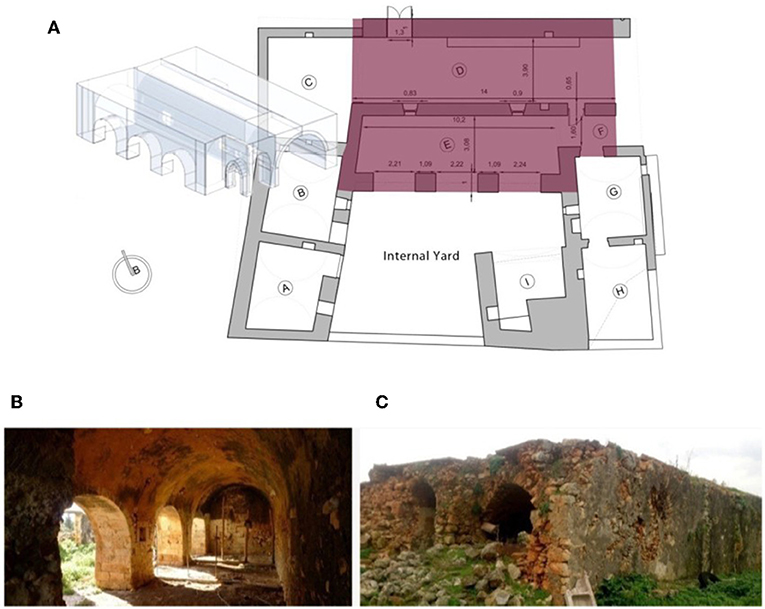
Figure 1. (A) Floor plan of eastern volume of the building complex with the rooms [D], [E], and [F] and a 3D model of these rooms is presented on the left part, (B) inside view of the room [E] with the pillars, and (C) outside view of the room [D] and the collapsed facade (Stavroulaki et al., 2018a).
The longitudinal external masonries have a thickness equal to 1.0 m and the thickness of the internal wall between the two spaces is 0.65 m. The thickness of the vaults is ~0.30–0.35 m, and they are covered by cement mortar without reinforcement with a thickness equal to 0.05–0.10 m. The type of the vertical walls is rubble stone masonry and rough-shaped bioclastic limestones of medium and small size have been used. In the vaults, carved stones with quite similar dimensions and for the bounding mortar, clay and small aggregates of limestone have been used.
The existence of the neighboring spaces [E] and [F] by which the space [D] communicates internally affects the mechanical deformation of the space [D], mainly applying restrictions to the lateral movement. The characteristics of this lateral support are unknown in advance. Thus, the estimation of the value of stiffness provided from this support is critical for the modeling of the space [D]. For this reason, in the present study, two scenarios were examined. First, a total rigid support was assumed across the top of the longitudinal wall limiting completely lateral movements. Second, a more flexible support was used assuming rods as lateral support. Furthermore, various values of the geometric characteristics were examined to have an exceptional comparison with the model in which the existing geometry in the present status was analyzed. For the analysis, 3D FE models were used for simulation of this construction of special geometry, stiffness, and mechanical behavior since simplified models could not be used, according to the existing research (Leftheris et al., 2006).
Mechanical Properties of the Masonry
Regarding the mechanical behavior of the masonry, it is known to have high strength for compression and acceptable shear strength, but very low strength for tensile forces. To determine the mechanical properties of the masonry, many equations can be used, which have been extracted by experimental research and given by the regulations. In our study, the European Regulation (EC6) guidelines were used in parallel with the Greek Annex of EC6. Thus, the compressive strength of the masonry is (MPa), where K is the coefficient that depends on the type of the masonry, f bc is the compressive strength of the stone, and f mc is the compressive strength of the bounding mortar.
Since tensile strength of the masonry is very low in many regulations, it is considered to be negligible. However, when horizontal loadings like earthquake or wind are applied, a bending tensile strength of the masonry is defined. The shear strength of an unreinforced masonry (f vk) is determined by testing or by experimental research (f vko) (EN1052-3, 4) or by specific values that the EC6 Regulation is proposed.
As presented by Stavroulaki et al. (2018b), the compressive strength of the stone is considered to be equal to 60 MPa in the analysis, while the compressive strength of the mortar equal to 2 MPa. The characteristic strength of the masonry is f wc = 14.4 MPa, and for the security coefficient, a value equal to 1.8 was used. In some areas where bad preservation status of the masonry exists, lower strength for the masonry was considered. In summary, the selected mechanical properties are shown in Table 1.
Finite Element Models
The first steps of the FE analysis of the previously mentioned, aggregated elongated vaulted structure was presented in Stavroulaki et al. (2018b). The dynamic behavior of these buildings was studied by the authors, considering the structure of space [D] as free without lateral restriction, with full restriction and as part of the existing geometry. In the FE models, the existing failures were simulated, and these models were analyzed for different earthquakes. From the results of the first part of the research, it seems that differences in the dynamic behavior of the structure were presented when the lateral restriction [zero horizontal (perpendicular the surface of the lateral wall) displacements] was considered in comparison with the model of the whole structure (real conditions of spaces [D], [E], and [F]). This became apparent from the numerical results of trends where the distribution of the stress values and the critical areas with stresses over the allowed values are located in different locations for the examined models. Furthermore, for the same earthquake, the values of the developed stresses are changing, and in particular, the values displayed for the model with the actual geometry are found between the values from the free model (lower values), and this is with rigid lateral restriction (higher values) (Stavroulaki et al., 2018b).
In the present study, data are given from the continuation of the above-mentioned research focused on the simulation of the neighboring building. It is often impossible to capture and record the structural elements of the neighboring structure, but the stiffness influences the dynamic behavior of the structure which is studied. This stiffness can be estimated by experimental measurements of the dynamic characteristics of the structure. For this reason, different models were analyzed based on modeling a flexible lateral restriction with rods and comparing the calculated natural frequencies. The main idea is that, in the future, the experimental modal frequencies should be measured and compared with the frequencies which are calculated by a FE modal analysis.
First, the model was assumed to have rigid lateral restriction (Model_1). Second, a flexible restriction assumed considering small rods at the place where the neighbor vaulted structure existed [Model_2 (with rods)], and final model with the real geometry of the aggregated vaulted buildings was used (Model_3) (see Figure 2A). The FE program MSC/Marc was used for analysis.
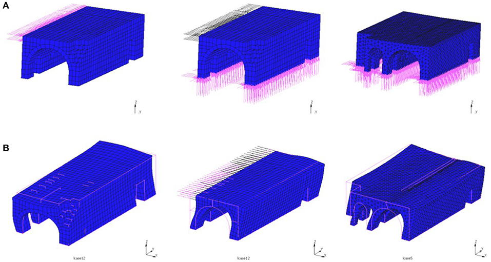
Figure 2. (A) Axonometric views of the finite element (FE) models and (B) first mode of the FE models [Model_1 (rigid restriction), Model_2 (rods), and Model_3].
The Model_1 model consists of 2,647 3D solid FEs with 3 df at each node. To achieve the appropriate simulation of the structure, several parameters were taken into account, such as the existent geometry (collapsed facade, areas with damage, material loss, etc.). Owing to failures caused by the descending moisture and the loose of bounding mortar in the lower parts of the walls, a reduced material strength was considered (75% of the rest of the masonry). The same parameters of the masonry pathology and boundary conditions were considered for the three examined models (see Figure 2) (with rigid restriction, with rods and the full geometry) for comparable analysis results. Since no signs of slip or movement phenomena exist in the structure, zero displacements on the base were considered. With respect to loadings other than gravity, vertical loads on the top were also applied for the modeling of the cement mortar which covers the vaults.
The analysis was done in a macromodel considering the masonry as homogeneous and isotropic material with an elastic–plastic behavior, which was described by a generalized Mohr–Coulomb parabolic model developed by Drucker and Prager.
Modal Analysis Results
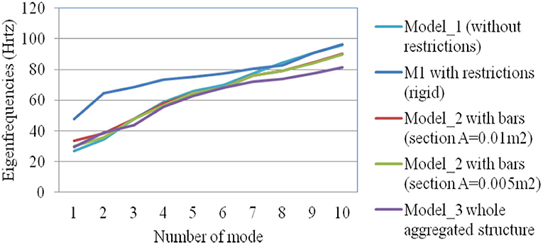
From the model analysis, the dynamic characteristics of the three models were calculated. The rigid lateral restrictions significantly affect the deformation of the structure as shown in Figure 2B, where the deformed shape of the models for the first eigenmode is presented. Instead, the application of elastic support through the bars led to a similar deformation in relation to the complete model. The same conclusion was extracted from the comparison of the values of the 10 eigenfrequencies calculated and presented in Figure 3.
Second Case: Two-Story Stone Masonry Buildings
The seismic behavior of low-rise masonry buildings, the influence of diaphragms, and the methods of strengthening have been studied by many researchers. Frequently, small-scale buildings were constructed in the laboratories and on seismic bank where earthquakes were applied to study their dynamic behavior. In particular, the method of intervention was studied, such as pretension by Tomazevic et al. (1996). In addition, the wooden floors found in traditional buildings were investigated for their behavior, their diaphragmatic or non-function, their reinforcement with diagrams, and their replacement with new reinforced concrete slabs (Kim and White, 2004; Peralta et al., 2004; Vintzileou et al., 2007; Stavroulaki and Amanatidou, 2008).
In the research of Tomazevic et al. (1996), three underscale masonry buildings were studied in the laboratory and in a seismic bank considering different kinds of floors which were subjected to seismic excitations. The masonry was from stone and mortar (cement–lime–sand), and the buildings had scaling equal to 1:4 (see Figure 4). In the present study, the dimensions of the building without scaling were used, which meant that the ground plan is 4.40 × 4.0 m and the height equal to 6 m. The wall thickness is equal to 48 cm, and the floors are equal to 20 cm. The openings exist only on two opposite walls with a length equal to 4.40 m. The technical characteristics were received by the experimental models that Tomazevic used in measurements sufficiently above simple seismic simulators in the laboratory (Tomazevic et al., 1996).
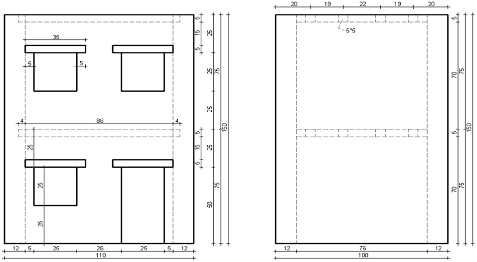
Figure 4. Side views (dimensions in cm) of the tested models (Tomazevic et al., 1996).
Mechanical Properties of the Masonry
As presented by Resta et al. (2013), a damage plasticity constitutive model can be effectively used within FE numerical simulation to study the static and dynamic behavior of masonry structures with complex geometry like masonry towers. In addition, it was mentioned that for masonry structures with complex geometry, the FE analysis gives reliable results compared with an equivalent frame model, which could not be used successfully.
In our case, the material was considered as homogeneous, and it was modeled by elastoplastic theory, using the simple forms of yield surfaces written in terms of the first and the second deviatoric stress invariants. Isotropic hardening is used to define the post-yield response rather than kinematic or mixed hardening due to its simplicity in the deformation of subsequent yield surfaces. The isotropic hardening rule assumes that the center of the yield surface remains stationary in the stress space but that the size (radius) of the yield surface expands due to hardening.
In the present study, the general-purpose FE program Marc was used in which several elastoplastic models can be used (Marc, 2008). In particular, the Mohr–Coulomb parabolic criterion was used, which is a first two-parametric yield surface for the maximum compression and tension. The model is the first one that takes shearing into account. It should be noted that the criterion considers the maximum difference between the major and the minor principal stresses only and does not consider the intermediate principal stress in the strength criterion. The Mohr–Coulomb strength criterion can be represented graphically, by Mohr's circle. Most of the classical engineering materials, including rock materials, somehow follow this rule in at least a portion of their shear failure envelope.
Parabolic Mohr–Coulomb criteria using stress invariants, written as follows (Stavroulaki and Liarakos, 2008):
where:
and
Using an elastoplastic model for the masonry, the computed plastic deformation indicates the degree of the developed damage and the areas which suffer most. The plastic strains are considered a relative variable which represent damage magnitude and distribution, and it can be used as a first approximation to study the influence of strengthening technique and the lateral restrictions modeling. More reliable material models that describe the cracking behavior in tension or crushing in compression will be used in future work. For the wooden beams, an elastic material was considered.
The characteristics properties of the materials that were based on the previous experimental (Tomazevic et al., 1996) are given in Table 2. The same material properties were used in the previous numerical study of the same building where the model validation was done with comparison between numerical and experimental results (Stavroulaki and Amanatidou, 2008).
Finite Element Models
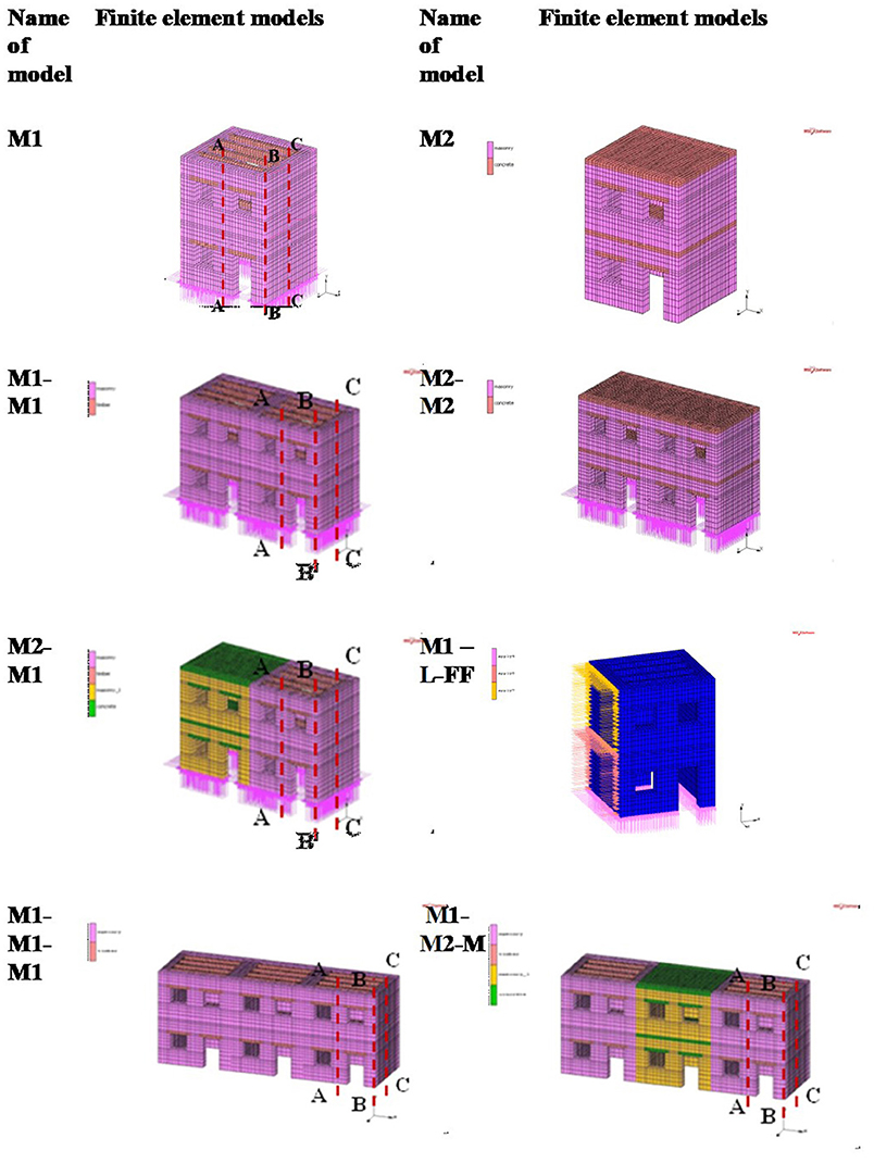
The following two basic models were used, which represent the typical type of old masonry house in a small historical city and the commonly applied intervention technique (replacement of timber floors with reinforced concrete slab). First is the Model 1 (M1), with timber floors, and second is the Model 2 (M2), with reinforced concrete slabs as floors (see Figure 5). The FEs that were used are three dimensions, eight-node, isoparametric, elements with 3 df per node. The number of nodes and elements is the following: Model 1, 17,480 nodes, 11,854 elements and Model 2, 19,488 nodes, 13,874 elements. The FE program MSC/Marc was used for analysis.
To investigate the dynamic behavior of aggregated masonry structures with the same or different structural system, the models M1-M1, M2-M2, and M2-M1 and models M1-M1-M1 and M1-M2-M1 (see Figure 5) were analyzed for two or three buildings in a row.
In addition, to investigate how to simulate neighboring structures for which we have no detailed geometrical and material data, new models were created with different boundary conditions. In particular, two cases were assumed. First, the stiffness of the neighboring structure is large enough to be considered as an ideal support and thus to have full restriction of the displacement perpendicular to the neighboring plane (fixed conditions).
Second, simulation of elastic support was considered in correspondence with the ground support, and various values of the coefficient of stiffness were investigated so the natural frequencies of the model and that of the actual situation to coincide. Two different coefficients of stiffness were assumed for the first and the ground floor. For example, the model M1-L-fixed represents the case where the model M1 is considered with full restriction in displacement perpendicular to the left face. The model M1_L-FF represents the case where the model M1 is considered with elastic constrain [face foundation (FF)] to the left face (see Figure 5).
Modal Analysis Results
A seismic design is based on the knowledge of the dynamic characteristics of the structure that determines the response of the structure under a seismic excitation. Consequently, for the estimation of the dynamic response of the structures having different horizontal structural systems, a frequency analysis was done first. The evaluation of the dynamic behavior of the structures with two different floor systems, namely, timber floor and reinforced concrete slab, under seismic excitations modal analysis of the various models is done, and the natural frequencies are extracted. In addition, the natural frequencies and the modes are calculated for different models which simulate the complex behavior of adjacent buildings with different stiffness and mass. The Lanczos method, which is considered suitable for large-scale structures, is used for the solution of the eigenproblem.
Indicative results of the examined models are shown in Figures 6–8 where, initially, the models M1 and M2 were assumed to have no boundary constraints on their side faces. The results of the modal analysis in the case of existing additional buildings or buildings on the left side with the same stiffness (models M1-M1, M2-M2, and M1-M1-M1) or different stiffness (models M2-M1 and M1-M2-M1) are compared, where fixed conditions (model M1-L-fixed) or FF (model M1-L-FF) are assumed to investigate the accuracy of the proposed simulation.
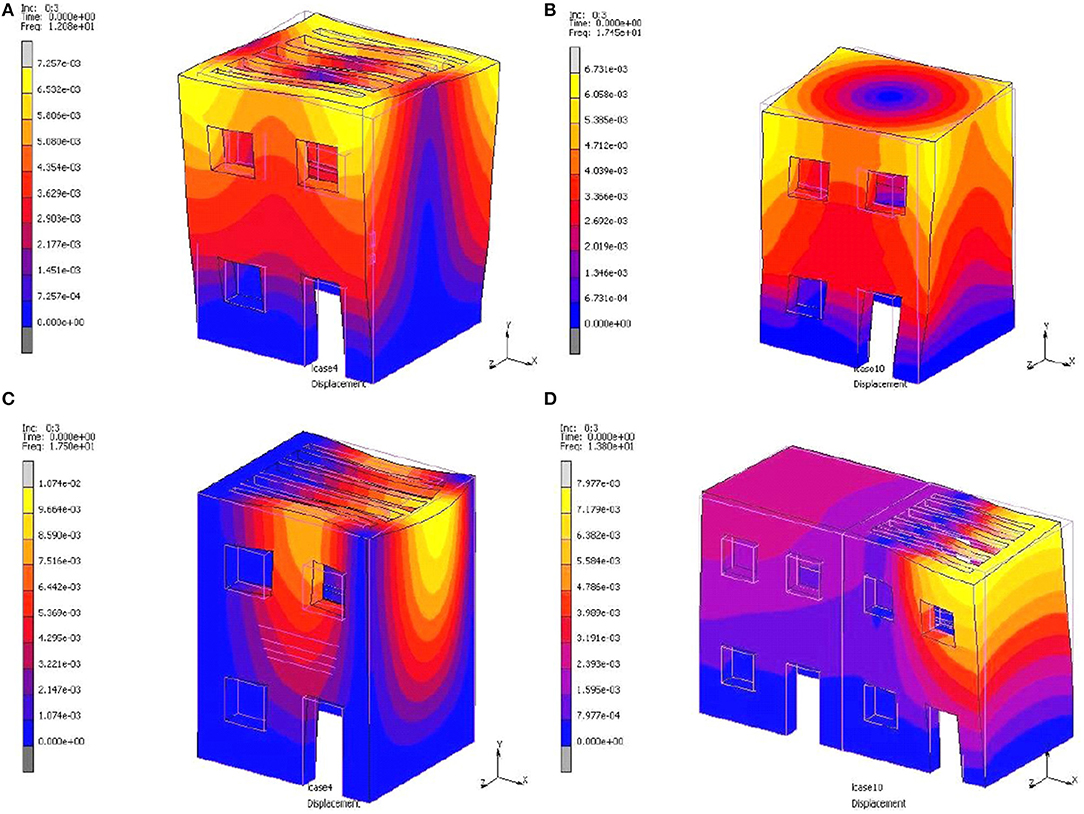
The contour plots of the displacement for the third mode are given in Figure 6. The assumption of fixed boundary condition on the left side could lead to overestimation of the vibration at the right side of model M1 (see Figure 6C). The replacement of timber floors with reinforced concrete slabs change the stiffness of the building (see Figures 6A,B). The existence of the adjacent structures with different stiffness (for example model M2-M1) leads to the increase in displacements, which are developed on the right free side of the building M1 and can be identified with forms of failure that have been observed in real structures (see Figure 6D) (Binda et al., 2000; Formisano, 2012).
Three different vertical sections are studied (see Figure 5) in the middle of the facade (section A-A), in the corner at the right edge (section B-B), and in the middle of the right-side face (section C-C). The first two modes refer to the oscillation along the walls with the openings (direction X, parallel to the arrangement of adjacent structures) and the walls without openings (direction y), respectively. The third mode refers to rotational oscillation, and the fourth refers to conveying oscillation simultaneously with rotation along the vertical axis. For section A-A (see Figure 5), the mode shape for the frequency of 11.09 Hz [first mode with indication (1)] and frequency of 15.5–16 Hz [third and fourth mode with the indications (3) and (4), respectively] are presented in Figures 7A,B. in addition, the mode shape for the frequency of 12–13 Hz [third mode with the indication (3)] of the section B-B (see Figure 5) is shown in Figure 8. The analysis of building M1 as an isolated structure leads to higher vibrations in comparison with those that are developed in the case of aggregate masonry buildings. The change in stiffness via the replacement of the wooden floors with reinforced concrete slabs influences the dynamic response of the model M1. The proposed assumption of FF on the left side face where the adjacent structures exist can satisfactorily approach the complex structure response (see Figures 7, 8). An iterative process was followed to estimate the equivalent spring stiffness of the foundation for the model with the proposed simulation to use its response to more accurately identify other models. More research is needed to have an even better estimation of the stiffness and to optimize this process for it to be carried out automatically.
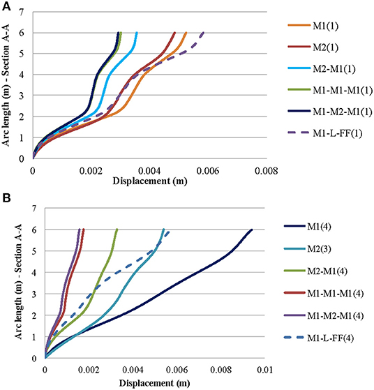
Figure 7. Displacements across section A-A for the first (11.09 Hz) (A) and the fourth mode (15.5–16 Hz) (B) of models: M1, M2, M2-M1, M1-M1-M1, M1-M2-M1, and M1-L-FF.
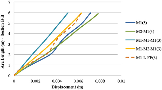
Figure 8. Displacements across section B-B for the third mode (frequency of 12–13 Hz) of models M1, M2-M1, M1-M1-M1, M1-M2-M1, and M1-L-FF.
In Figure 9, the variation of 10 eigenfrequencies between some of the examined models is given. The frequencies in which only the timber beams were vibrated are not included to these diagrams. The stiff reinforced concrete slab affects the whole structural stiffness, especially at the higher modes (out of plane buckling of the walls and torsion around a vertical axis) (see Figures 9A,B). In particular, we observe that, in almost all cases examined, the full constraint on the side of the adjacent building leads to higher values of frequencies, especially for the upper modes, which means that the model is stiffer than the actual construction (simulation of both or three buildings in detail, see Figures 9C,D). The simulation with elastic support has led to a good approximation of the frequencies of the first modes (see Figures 9A,B).
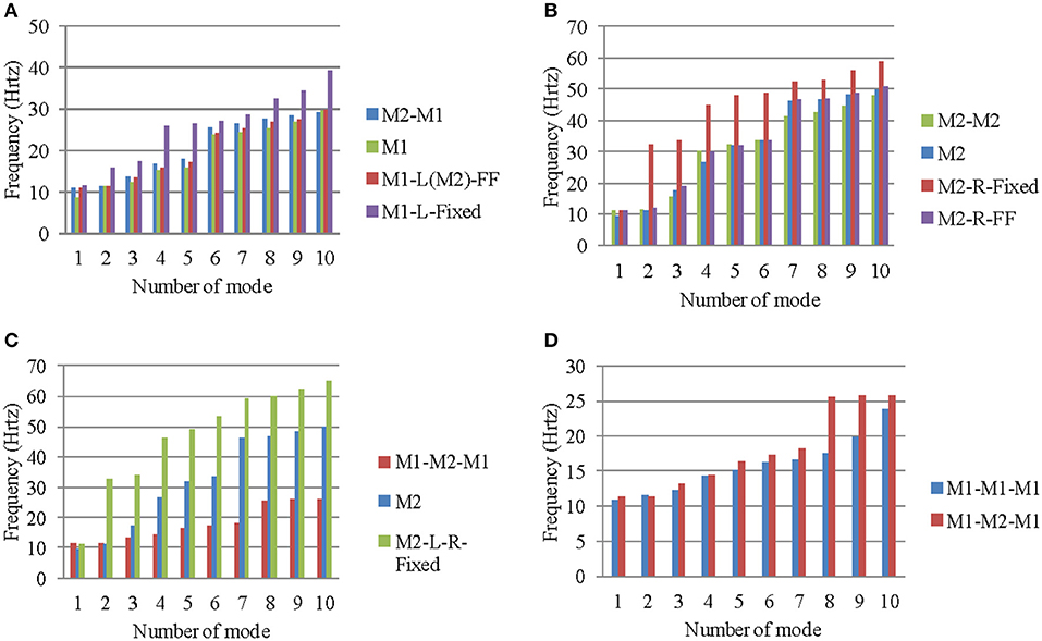
Figure 9. Variation of frequencies of models: (A) M2-M1, (B) M2-M2, (C) M1-M2-M1 and the relevant boundary assumptions, and (D) M1-M1-M1 and M1-M2-M1.
Dynamic Analysis Results
The non-linearity of the masonry and the material was used for the strengthening influence on the dynamic response of the masonry buildings. In the FE analysis of the masonry structure, an elastoplastic model for the masonry can be used for the estimation of the plastic deformations, which indicate the critical areas where damage could develop. The effectiveness of the strengthening method and its influence on the dynamic behavior of the strengthened structure can be estimated by the study of the analysis results for the structural model with and without the application of the strengthening technique.
The seismic load that was applied at the base of the models is the North–South component of earthquake in Montenegro, 15.04.1979, from the recording to the Petrovac (see Figure 10), with peak value equal to 9.47 cm. For practical reasons, the first 4 s of recording was studied for all modes, except the analysis of the first two examined models M1 and M2 where the first 8 s of recording was used.

Figure 10. N–S component of the Montenegro earthquake of 15.04.1979 and the Petrovac record (Stavroulaki and Amanatidou, 2008).
The base excitation was applied first in the z direction (perpendicular the face with the openings) and second in the x direction (perpendicular the face without the openings). In the other two directions, the bases of the models were considered to have zero movements.
From the transient dynamic analysis, the strains and especially the plastic part, which indicates the initiation of cracks, were calculated. From the distribution of the equivalent plastic strains, the critical areas were located mainly at the sides that are vertical in the direction of earthquake, around the openings, and at the pessary at the middle of the wall with the openings. These are also the critical areas based on the failure picture of these kinds of structures after earthquakes around the world. Comparing the first two examined models M1 and M2 for all the examined load cases, the regions with plastic strains were mainly reduced to the first floor when reinforced concrete slabs were considered at the floor levels (see Figure 11). In addition, the weight of the concrete slab led to the development of higher strains. Similar conclusions were extracted by experimental measurements which were done by Tomazevic to models in scale with the same geometry but with different masonry material (Tomazevic, 1987; Tomazevic et al., 1996; Paquette and Bruneau, 2006).
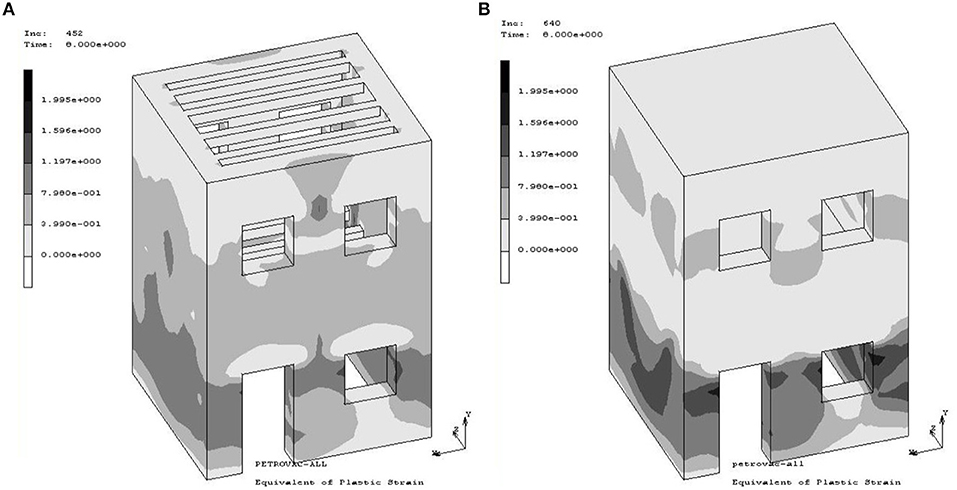
Figure 11. Equivalent plastic strains at time 8 s of the Petrovac record applying in the z direction (perpendicular face with openings) for models (A) M1 and (B) M2.
For the models M1-M1-M1 and M1-M2-M1 where three aggregated masonry buildings were studied, the base excitation was applied in the x direction (perpendicular the walls without the openings). These models represent the case where the middle building replacement of the timber floors with reinforced concrete slabs is applied. The replacement of the original timber floor or roof with a new one made with reinforced concrete is a common practice last years and seems to have negative effects on many old masonry structures to seismic actions (Carocci, 2012). Experience has shown that catastrophic effects may occur also in neighboring buildings, especially when they have reduced strength.
In cases where intervention was applied only to the middle building (model M1-M2-M1), the dynamic response was changed (see Figure 9D). The displacements of these two modes are shown in Figures 12A,B. Comparison of the equivalent plastic strains, which were developed in the first 4 s of the analysis is given in Figures 12C,D. The possible failures were presented in areas where expected in relation to the experience of real structures with quite similar geometric characteristics. The increase in the stiffness between the interventions led to the increase in the failures.
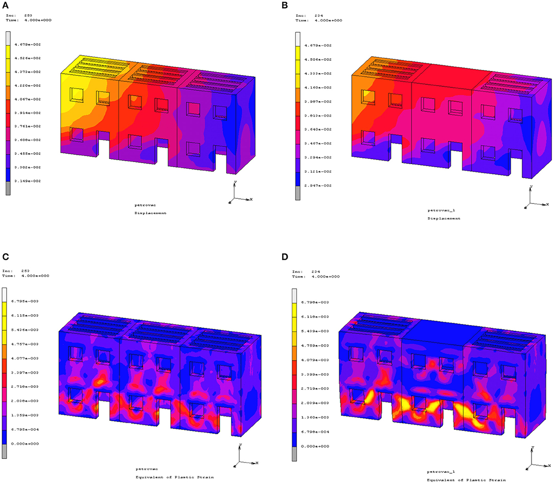
Figure 12. Displacements (in m) of models (A) M1-M1-M1 and (B) M1-M2-M1 and equivalent plastic strains of models, (C) M1-M1-M1 and (D) M1-M2-M1, at 4 s.
As already mentioned, the analysis of a masonry building as an isolated structure lead to an overestimation of the dynamic response, an unrealistic picture of the developed stress, and the assessment of the areas with failures. This is also confirmed in Figure 13 where the displacement across the sections A-A and C-C for the last step of dynamic analysis is shown. With dot lines, the results of two different cases of the proposed FF are given. The best estimate of stiffness leads to a more accurate approach to actual dynamic response of the aggregated buildings.

Figure 13. Displacements X (in m) of sections A-A and C-C of models M1, M1-M1-M1, M1-M2-M1, and M1-L-FF (two cases) at 4 s.
Conclusion
The aggregated buildings are the typical structural system for monastic and agricultural compounds and old town centers where the masonry buildings have been built in continuity. This connection influences the dynamic behavior of each building, and the restrictions that are developed in between the adjacent structures must be taken into account in the static and dynamic analysis. The interaction of structures which belong to a complex is documented by many researchers, and the results have been shown in the picture of faults in masonry structures after earthquakes. Various methods of simulation for adjacent structures have been proposed, which are often based on the use of simplified simulation methods of structures, e.g., macroelements, equivalent frames, etc. At the same time, monumental and traditional constructions, due to the fact that they often show different building phases, a variety of materials and structural elements, and structural failures simplifying simulation methods are difficult to use in the analysis. For example, buildings with openings of varying sizes and shapes in diffuse locations, arched and vaulted structures for the ground floor, connection problems to the walls, existence of different types of horizontal diaphragms, etc. can be modeled with accuracy by the FE method and 3D simulation.
In the present work, a general method for simulating the restrictions that are developed between aggregated masonry buildings is proposed and which could be applied independently of the geometric characteristics of adjacent structures due to unavailability of any data or the inability to access the neighboring buildings. It is based on the application of elastic supports on the face or faces where adjacent buildings exist. The final identification of the model, as well as the adjustment of the proposed elastic supports, was done in comparison with the dynamic characteristics of the complex to which the building under consideration belongs. This can be extended in real cases where the model identification will be done in comparison with experimental measurements of the dynamic characteristics. Considering the stiffness of the elastic supports proposed on the basis of the dynamic features, we transfer all the information related to the stiffness of adjacent buildings as well as their existing pathology (therefore not only the geometrical characteristics but also the existing strength of the materials and the structural peculiarities).
First results of this research are presented in the paper via two different case studies. In the first case, a two-vaulted structure, which is part of an old monastery, was studied, and rod elements were used to model the side restrictions. The replacement of the old timber floors with reinforced concrete slabs, widely used as restoration techniques, affect the mass and the stiffness of the structure and lead to dynamic behavior changes. For this reason, in the second case, a two-story masonry building with timber floors was studied both as an isolated structure and in connection with other two-story masonry buildings with the same geometric and material data distinguished by timber floors or reinforced concrete slabs. Various arrangements of the two above types of buildings were studied, and an elastic foundation was proposed as simulation method for the support of the adjacent structure. The natural frequencies of the real building complex were estimated by FE model of all the aggregated structures and were then used for the dynamic identification of the simplified model. From the results, it was noticed that the examined intervention technique on the two-floor masonry building leads to changes of the dynamic behavior of the structure as an isolated structure or as an aggregated masonry building. This was especially true when the examined building belonged to a complex and was influenced by the application of this intervention onto an adjacent building. This means that the decision of the applied intervention technique must be taken after the study of its influence on the neighboring structures. From the results, it can be concluded that the consideration of rigid restriction increases the dynamic eingenfrequencies, which means that the model simulates a structure with higher stiffness in comparison with the model of the real condition. This is critical to the decision of the intervention technique application. A flexible support could better simulate the real interaction; therefore, it is important to find the way to model this condition.
Future work must be done to estimate the coefficient stiffness of the elastic foundation that was proposed and was used instead of the adjacent building and be done automatically. In addition, the application of the presented research to real aggregated masonry structures must be carried out where the experimental estimation of the dynamic characteristics would be available for the dynamic identification of the FE models.
Data Availability Statement
All datasets generated for this study are included in the article/supplementary material.
Author Contributions
The author confirms being the sole contributor of this work and has approved it for publication.
Conflict of Interest
The author declares that the research was conducted in the absence of any commercial or financial relationships that could be construed as a potential conflict of interest.
References
Barbieri, G., Biolzi, L., Bocciarelli, M., Fregonese, L., and Frigeri, A. (2013). Assessing the seismic vulnerability of a historical building. Eng. Struct. 57, 523–535. doi: 10.1016/j.engstruct.2013.09.045
Bartoli, G., Betti, M., Galano, L., and Zini, G. (2019). Numerical insights on the seismic risk of confined masonry towers. Eng. Struct. 180, 713–727. doi: 10.1016/j.engstruct.2018.10.001
Betti, M., Galano, L., and Vignoli, A. (2014). Comparative analysis on the seismic behaviour of unreinforced masonry buildings with flexible diaphragms. Eng. Struct. 61, 195–208 doi: 10.1016/j.engstruct.2013.12.038
Binda, L., Penazzi, D., Valluzzi, M. E., Cardani, G., Baronio, G., and Modena, C. (2000). “Behaviour of historic masonry buildings in seismic areas: lessons learned from the Umbia-Marche earthquake,” in 12th International Brick/Block Masonry Conference (Madrid).
Cardoso, R., Lopes, M., and Bento, R. (2005). Seismic evaluation of old masonry buildings. Part I: method description and application to a case-study. Eng. Struct. 27, 2024–2035. doi: 10.1016/j.engstruct.2005.06.012
Carocci, C. F. (2012). Small centres damaged by 2009 L'Aquila earthquake: on site analyses of historical masonry aggregates. Bull. Earthquake Eng. 10, 45–71. doi: 10.1007/s10518-011-9284-0
Castellazzi, G., D'Altri, A. M., de Miranda, S., Chiozzi, A., and Tralli, A. (2018). Numerical insights on the seismic behavior of a nonisolated historical masonry tower. Bull. Earthquake. Eng. 16, 933–961. doi: 10.1007/s10518-017-0231-6
Castori, G., Borri, A. D., Maria, A., Corradi, M., and Sisti, R. (2017). Seismic vulnerability assessment of a monumental masonry building. Eng. Struct. 136, 454–465. doi: 10.1016/j.engstruct.2017.01.035
Cetinkaya, N. (2011). Karakocan-Elazig earthquake and masonry structures. Nat. Hazards Earth Syst. Sci. 11, 11–16. doi: 10.5194/nhess-11-11-2011
Clementi, F., Pierdicca, A., Formisano, A., Catinari, F., and Lenci, S. (2017). Numerical model upgrading of a historical masonry building damaged during the 2016 Italian earthquakes: the case study of the Podesta‘ palace in Montelupone (Italy). J. Civ. Struct. Health Monit. 7, 703–717. doi: 10.1007/s13349-017-0253-4
Diaferio, M., Foti, D., and Giannoccaro, N. I. (2015). “Identification of the modal properties of a squat histroric tower for the tuning of a FE model,” in 6th International Operational Modal Analysis Conference (Gijón).
Ercan, E., Hökelekli, E., Demir, A., and Nohutçu, H. (2017). “Finite element model updating of historical minaret via operational modal analysis,” in 7th International Operational Modal Analysis Conference (Ingolstadt).
Formisano, A. (2012). “Seismic behaviour and retrofitting of the Poggio Picenze Historical Centre damaged by the L'Aquila earthquake,” in Proceedings of the Eleventh International Conference on Computational Structures Technology (Stirlingshire: Civil-Comp Press), 199. doi: 10.4203/ccp.99.199
Formisano, A. (2016). Theoretical and numerical seismic analysis of masonry building aggregates: case studies in San Pio Delle Camere (L'Aquila, Italy). J. Earthquake Eng. 0, 1–19. doi: 10.1080/13632469.2016.1172376
Formisano, A., Florio, G., Landolfo, R., and Mazzolani, F. M. (2015). Numerical calibration of an easy method for seismic behavior assessment on large scale of masonry building aggregates. Adv. Eng. Softw. 80, 116–138. doi: 10.1016/j.advengsoft.2014.09.013
Formisano, A., and Massimilla, A. (2018). A novel procedure for simplified nonlinear numerical modeling of structural units in masonry aggregates. Int. J. Archit. Herit. 12, 1162–1170. doi: 10.1080/15583058.2018.1503365
Foti, D., Diaferio, M., Giannoccaro, N. I., and Mongelli, M. (2012). Ambient vibration testing, dynamic identification and model updating of a historical tower. NDT&E Int. 47, 88–95. doi: 10.1016/j.ndteint.2011.11.009
Greco, A., Lombardo, G., Pantò, B., and Famà, A. (2018). Seismic vulnerability of historical masonry aggregate buildings in oriental Sicily. Intl J. Archit. Herit. doi: 10.1080/15583058.2018.1553075. [Epub ahead of print].
Kim, S. C., and White, D. W. (2004). Nonlinear analysis of a one-story low-rise masonry building with a flexible diaphragm subjected to seismic excitation. Eng. Struct. 26, 2053–2067. doi: 10.1016/j.engstruct.2004.06.008
Leftheris, B. P., Stavroulaki, M. E., Sapounaki, A. C., and Stavroulakis, G. E. (2006). Computational Mechanics for Heritage Structures. Boston, MA: WIT Press.
Magenes, P., Penna, A., Rota, M., Galasco, A., and Senaldi, I. (2012). “Shaking table test of a full scale stone masonry building with stiffened floor and roof diaphragms,” in Proceeding of the 15th World Conference on Earthquake Engineering (Lisbon).
Maio, R., Vicente, R., Formisano, A., and Varum, H. (2015), Seismic vulnerability of building aggregates through hybrid indirect assessment techniques. Bull. Earthquake Eng. 13, 2995–3014. doi: 10.1007/s10518-015-9747-9
Paquette, J., and Bruneau, M. (2006). Pseudo-dynamic testing of unreinforced masonry building with flexible diaphragm and comparison with existing procedures. Constr. Build. Mater. 20, 220–228. doi: 10.1016/j.conbuildmat.2005.08.025
Peralta, D. F., Bracci, J. M., and Hueste, M. B. D. (2004). Seismic behavior of wood diaphragms in pre-1950s unreinforced masonry buildings. J. Struct. Eng. 13, 2040–2050. doi: 10.1061/(ASCE)0733-9445(2004)130:12(2040)
Ramos, L. F., and Lourenco, P. B. (2004). Modeling and vulnerability of historical city centres in seismic areas: a case study in Lisbon. Eng. Struct. 26, 1295–1310. doi: 10.1016/j.engstruct.2004.04.008
Resta, M., Fiore, A., and Monaco, P. (2013). Non-linear finite element analysis of masonry towers by adopting the damage plasticity constitutive model. Adv. Struct. Eng. 16, 791–803. doi: 10.1260/1369-4332.16.5.791
Scotta, R., Trutalli, D., Marchi, L., and Pozza, L. (2018). Seismic performance of URM buildings with in-plane non-stiffened and stiffened timber floors. Eng. Struct. 167, 683–694. doi: 10.1016/j.engstruct.2018.02.060
Senaldi, I., Magenes, G., and Penna, A. (2010). Numerical investigations on the seismic response of masonry building aggregates. Adv. Mater. Res. 133–134, 715–20. doi: 10.4028/www.scientific.net/AMR.133-134.715
Stavroulaki, M., and Liarakos, V. (2008). “Parametric finite element analysis of masonry structures using different constitutive models,” in Proceedings of 6th GRACM International Congress on Computational Mechanics (Thessaloniki).
Stavroulaki, M. E., and Amanatidou, Ch. K. (2008). “Seismic behavior of an unreinforced masonry building with various floor systems,” Proceedings of the Ninth International Conference on Computational Structures Technology (Athens). doi: 10.4203/ccp.88.236
Stavroulaki, M. E., Anousakis, A., and Aikaterini Mesaritaki, A. (2018a). “Finite element analysis of aggregated elongated vaulted structures,” in 9th GRACM International Congress on Computational Mechanics (Chania).
Stavroulaki, M. E., Drosopoulos, G. A., Tavlopoulou, E., Skoutelis, N., and Stavroulakis, G. E. (2018b). Investigation of the structural behavior of a masonry castle by considering the actual damage. Int. J. Masonry. Res. Innov. 3, 1–33. doi: 10.1504/IJMRI.2018.089046
Stavroulaki, M. E., Riveiro, B., Drosopoulos, G. A., Solla, M., Koutsianitis, P., and Stavroulakis, G. E. (2016). Modeling and strength evaluation of masonry bridges using terrestrial photogrammetry and finite elements. Adv. Eng. Softw. 101, 136–148. doi: 10.1016/j.advengsoft.2015.12.007
Tomazevic, M. (1987). Dynamic modeling of masonry buildings: storey mechanism model as a simple alternative. Earthquake Eng. Struct. Dyn. 15, 731–749. doi: 10.1002/eqe.4290150606
Tomazevic, M., Lutman, M., and Weiss, P. (1996). Seismic upgrading of old brick-masonry urban houses: tying of walls with steel ties. Earthquake Spectra 12, 599–622. doi: 10.1193/1.1585898
Vicente, R., Rodrigues, H., Varum, H., and Mendes da Silva, J. A. R. (2011). Evaluation of strengthening techniques of traditional masonry buildings: case study of a four-building aggregate. J. Perform. Constr. Fac. 25, 202–216. doi: 10.1061/(ASCE)CF.1943-5509.0000164
Keywords: masonry, aggregated buildings, dynamic analysis, finite element analysis, horizontal diaphragms
Citation: Stavroulaki ME (2019) Dynamic Behavior of Aggregated Buildings With Different Floor Systems and Their Finite Element Modeling. Front. Built Environ. 5:138. doi: 10.3389/fbuil.2019.00138
Received: 27 January 2019; Accepted: 06 November 2019;
Published: 22 November 2019.
Edited by:
Eleni N. Chatzi, ETH Zürich, SwitzerlandReviewed by:
Michele Betti, University of Florence, ItalyJelena Milosevic Ilic, Instituto Superior Técnico, Portugal
Copyright © 2019 Stavroulaki. This is an open-access article distributed under the terms of the Creative Commons Attribution License (CC BY). The use, distribution or reproduction in other forums is permitted, provided the original author(s) and the copyright owner(s) are credited and that the original publication in this journal is cited, in accordance with accepted academic practice. No use, distribution or reproduction is permitted which does not comply with these terms.
*Correspondence: Maria E. Stavroulaki, bXN0YXZyQG1yZWQudHVjLmdy
 Maria E. Stavroulaki
