 K. Krishnan
 Koushik Halder
 Debarghya Chakraborty
94% of researchers rate our articles as excellent or good
Learn more about the work of our research integrity team to safeguard the quality of each article we publish.
Find out more
ORIGINAL RESEARCH article
Front. Built Environ., 15 November 2019
Sec. Transportation and Transit Systems
Volume 5 - 2019 | https://doi.org/10.3389/fbuil.2019.00134
This article is part of the Research TopicGeotechnical Innovation for Transport InfrastructuresView all 12 articles
The present study adopts lower bound finite element limit analysis technique in association with non-linear optimization to compute the seismic bearing capacity of a strip footing placed over an embankment of anisotropic clay. The influence of seismic loading is incorporated in terms of a horizontal seismic acceleration coefficient. The bearing capacity factor Nc of the strip footing is obtained for various combinations of (i) slope angle, (ii) footing setback distance, (iii) horizontal seismic acceleration coefficient, and (iv) anisotropic strength ratio of clay. The bearing capacity factor of the strip footing increases with the increasing setback distances. However, beyond a certain setback distance, hardly any influence is found. For a particular footing position and constant value of horizontal seismic acceleration coefficient, the magnitude of bearing capacity factor increases with the increase in anisotropic strength ratio. However, the percentage increment in the bearing capacity reduces when the value of anisotropic strength ratio becomes greater than one. In addition, the bearing capacity reduces with the increasing slope angle and horizontal seismic acceleration coefficient. Failure patterns are obtained to understand the failure mechanism.
In recent times, shortage of construction land compels the people to build structures on the embankment; even on its edge or side face. Construction of shallow foundations for short storeyed buildings and bridge abutments, roadways, and railways on flood plains or riverbanks are the perfect examples of such structures. The presence of slope on both the sides of the footing reduces the bearing capacity of the footing, which significantly enhances the vulnerability of the structures (Georgiadis, 2009; Chakraborty and Kumar, 2013; Chakraborty and Mahesh, 2015; Leshchinsky, 2015; Halder and Chakraborty, 2018; Raj et al., 2018; Halder et al., 2019). The risk and vulnerability of the structures increases further under the seismic loading, generated during an earthquake (Kumar and Mohan Rao, 2003; Choudhury and Subba Rao, 2006; Yang, 2009; Kumar and Chakraborty, 2013; Chakraborty and Mahesh, 2015; Halder et al., 2018; Halder and Chakraborty, 2019). The literature review reveals that although there are many studies available for the computation of the bearing capacity of footing on the embankment under seismic loading, no one has considered the effect of anisotropy of clay on the bearing capacity of a strip footing placed on an embankment and subjected to seismic loading. The effect of anisotropy is very much significant for undrained clay (Jakobson, 1955; Lo, 1965; Bishop, 1966; Duncan and Seed, 1966; Davis and Christian, 1971). Hence, the introduction of anisotropy in numerical analysis increases the accuracy of the analysis towards field condition. Davis and Christian (1971) formulated an anisotropic failure criterion (Equation 2) for cohesive soil in the form of an ellipse by using the anisotropic strength ratio (b/a) which is a function of undrained shear strengths su0, su45, and su90. In the present analysis, the effect of anisotropy of clay is incorporated using the formulation proposed by Ukritchon and Keawsawasvong (2018) using the yield function of Davis and Christian (1971). From here, throughout the article, DC indicates the yield criterion of Davis and Christian (1971). The advantage of DC yield function is associated with the consideration of three parameters (suo, su90, and su45); whereas, most of the other anisotropic yield criterions are based on two parameters (suo and su90). The parameters mentioned above are the undrained shear strengths of clay measured in different orientations (δ): suo (plane strain compression, δ = 0°), su90 (plane strain tension, δ = 90°), and su45(simple shear, δ = 45°). It is also indicated by Ukritchon and Keawsawasvong (2018) that the three-parameter model simulates the actual failure envelope in a better way with respect to other models. The influences of other parameters investigated in the study are slope inclination angle (β), footing setback distance (S), and seismic acceleration coefficient (kh). With the consideration of all the parameters mentioned above, the present study computes the bearing capacity of a strip footing situated over an embankment of anisotropic clay.
The objective of the present study is to determine the bearing capacity factor Nc of a rigid, rough and surface strip footing of width B placed over an embankment of anisotropic clay, in the presence of horizontal earthquake acceleration (khg) using the lower bound finite element limit analysis method. A non-linear optimization technique based on the second-order cone programming (SOCP) method is used. The embankment faces are assumed to incline at an angle β with the horizontal axis. The classical bearing capacity equation of Terzaghi (1943) reduces to Equation (1), as there is no presence of frictional property of soil and overburden pressure in the ground.
where, Qu is the ultimate collapse load determined from lower bound limit analysis and suav = (su0 + su90) is the average undrained shear strength of clay.
The problem domain used in the present study is represented by Figure 1A. The domain is varied up to a length and depth of 7.5B−15B in the horizontal and vertical directions. Figure 1A also shows the stress boundary conditions employed on different boundary edges. With the absence of any overburden pressure, the normal and shear stresses are zero along the ground surface (MI and JN) and inclined faces (RM and NO) of the embankment. In order to account the footing roughness, an equation: |τxy| ≤ suav is adopted. The semi-infinite and perfectly plastic soil mass is assumed to follow associated flow rule and DC yield criterion. The effect of pseudo-static lateral earthquake force is considered in the study by introducing a lateral shear force (Qh = khQu) along the footing-soil interface IJ.
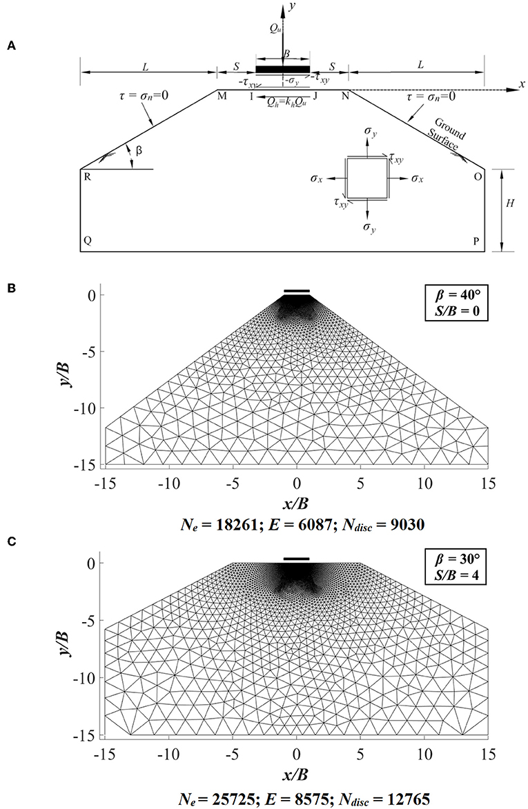
Figure 1. (A) Problem domain with stress boundary conditions; (B) finite-element mesh for S/B = 0 and β = 40°; (C) finite-element mesh for S/B = 4 and β = 30°.
The finite element mesh is first created using ABAQUS software1. Then the coordinates of the mesh are transferred to MATLAB2. Figures 1B,C show the ABAQUS generated finite element mesh, which is later used in MATLAB in order to obtain the collapse load of footing. In Figures 1B,C, Ne, E, and Ndisc denote the number of nodes, elements and discontinuity edges, respectively.
The present study uses the lower bound finite element limit analysis formulation of Sloan (1988). The plane strain lower bound formulation of Sloan (1988) has certain unique qualities such as: (i) it requires only the shear strength parameters for solving any stability problem (ii) it gives safe and conservative solution of the collapse load (iii) the assembly of elements is easier due to the distinct node numbers for each element. As per the lower bound theorem, any statically admissible stress field that satisfies the (i) element equilibrium condition, (ii) stress boundary condition, and (iii) yield criteria, gives a safe solution of the true collapse load. Among the above three, the first two conditions are the equality constraints and the third one is an inequality constraint. In the finite element lower bound limit analysis formulation, the elements are assigned distinct node numbers. Hence, there arises a discontinuity between the edges of shared elements. The discontinuity of the stresses is considered by imposing an additional equality constraint. To solve any stability problem, the above four conditions need to be satisfied.
Equation (2) gives the DC yield condition for anisotropic clay below.
where, σx and σy are the normal stresses on x and y directions, respectively. , , and are the center, major semi-axes, and minor semi-axes of the elliptical yield surface formulated by DC yield criteria. The b/a ratio: the ratio between the minor and major axes, respectively, is used as a factor for anisotropic strength.
The objective function is generated by integrating the normal stresses along the footing-soil interface. The canonical form of the optimization scheme is given in Equation (3). A MATLAB code is written to form the canonical structures of the formulation; whereas, an optimization toolbox MOSEK3 is used to carry out the non-linear optimization.
Where Ag and Bg are the global matrix and vector, respectively constituting equality constraints. A1SOCP, A2SOCP, and BSOCP are the yield constraint matrices and vector, respectively. {σ} is the nodal stress vector and {ξ} is the nodal slag variable vector.
The variation of bearing capacity factor Nc with respect to kh is determined for various b/a ratios ranging from 0.8 to 1.2. The Figures 2–4 show the results obtained for different β (= 10°, 20°, 30°, and 40°) and S/B (0, 2, and 4) values. The results indicate that as the footing moves away from the slope edge, the bearing capacity increases. However, after a particular setback distance of footing, there is no further increment in the value of bearing capacity factor. The reason behind this is the reduction in the influence of plastic zone over the slope when setback distance is increased. Similar results are also obtained in Chakraborty and Kumar (2015) and Halder and Chakraborty (2018). Results also illustrate that the bearing capacity increases with the increase in anisotropic strength ratio (b/a). It is noted that the increment in Nc value is higher for b/a < 1. However, the increment becomes constant when b/a > 1. For a slope of β = 30°, S/B = 0, and kh = 0, the increase in Nc value is 57.81% with the increase in the value of b/a from 0.8 to 1.0. Whereas, when b/a ratio is increased from 1.0 to 1.2, the percentage increase in the Nc value is reduced to 9.41%. The decrease in Nc value with the increase in β also is evident from the results. For example, when b/a ratio is reduced from 1.0 to 0.8 for a footing with S/B = 0, the reduction in Nc value becomes higher from 13.75 to 45.43% for the increase in β value from 10 to 40°, respectively. In the same way when setback distance is varied from S = 0B−4B for a slope angle of 30°, the magnitude of Nc value reduces from 36.63 to 5.85% for the reduction in b/a ratio from 1.0 to 0.8.
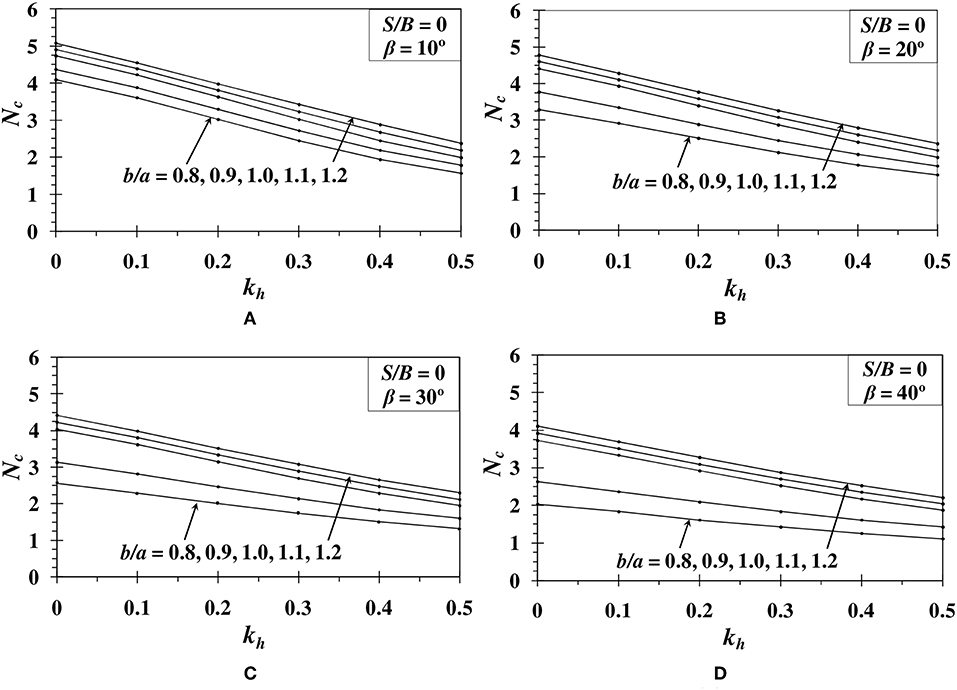
Figure 2. Variation of Nc with respect to kh for S/B = 0 and (A) β = 10°; (B) β = 20°; (C) β = 30°; (D) β = 40°.
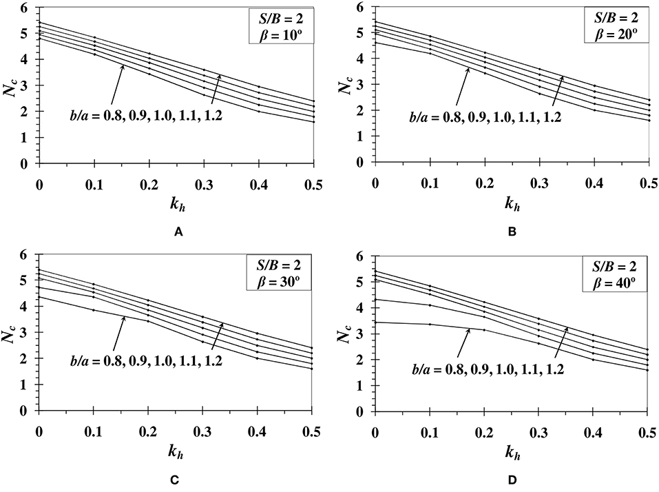
Figure 3. Variation of Nc with respect to kh for S/B = 2 and (A) β = 10°; (B) β = 20°; (C) β = 30°; (D) β = 40°.
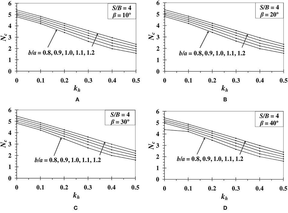
Figure 4. Variation of Nc with respect to kh for S/B = 4 and (A) β = 10°; (B) β = 20°; (C) β = 30°; (D) β = 40°.
The state of stress at any point with respect to collapse is determined in terms of F as given in Equation (2). As per the DC failure criterion, the soil fails or enters plastic state when F ≥ 1. When F < 1, the soil will remain in a non-plastic state. The failure mechanism of an embankment for S/B = 0 and S/B = 4 are shown in Figures 5A–H, 6A–H, respectively. It is evident from Figure 5 that when S/B = 0, the failure surface extends to the slope face easily. It is also clear that when b/a ratio is reduced from 1.0 to 0.8, the failure surface extends to a greater depth. The influence of seismic force is well-understood from the Figures 5C,D,G,H. With the consideration of earthquake loading, the failure surface shifts more toward the slope face in the direction of seismic force. From Figures 6A–D, it is seen that the plastic zone is developed locally within the horizontal surface when b/a = 1 (isotropic condition). However, when the b/a ratio is decreased to 0.8 as in Figures 6E–H, additional to the local failure due to the footing on horizontal surface, the plastic zone is developed in the slope as well.
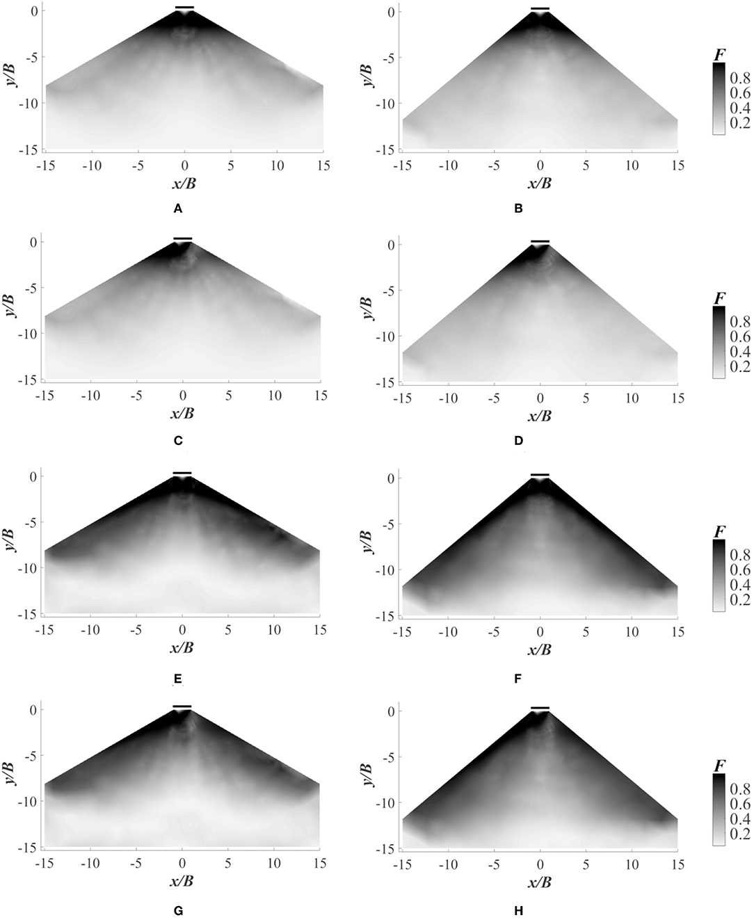
Figure 5. Failure contours for S/B = 0 and b/a = 1 with (A) β = 30°, kh = 0; (B) β = 40°, kh = 0; (C) β = 30°, kh = 0.1; (D) β = 40°, kh = 0.1; and failure contours for S/B = 0 and b/a = 0.8 with (E) β = 30°, kh = 0; (F) β = 40°, kh = 0; (G) β = 30°, kh = 0.1; (H) β = 40°, kh = 0.1.
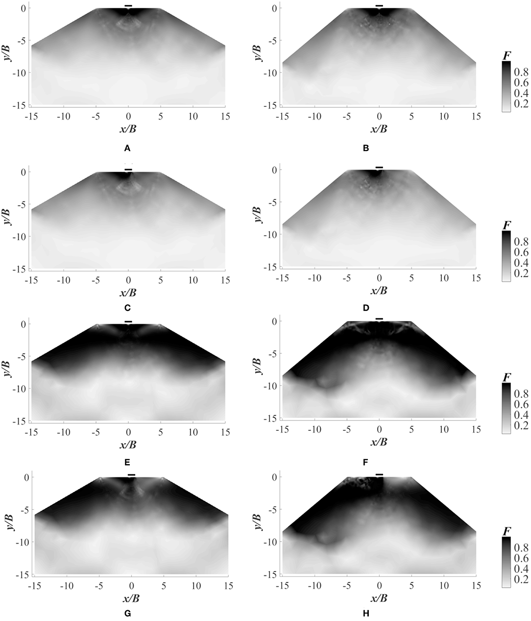
Figure 6. Failure contours for S/B = 4 and b/a = 1 with (A) β = 30°, kh = 0; (B) β = 40°, kh = 0; (C) β = 30°, kh = 0.1; (D) β = 40°, kh = 0.1; and failure contours for S/B = 4 and b/a = 0.8 with (E) β = 30°, kh = 0; (F) β = 40°, kh = 0; (G) β = 30°, kh = 0.1; (H) β = 40°, kh = 0.1.
The values of Nc calculated from the present study for isotropic condition (b/a = 1) are compared with the results of Chakraborty and Mahesh (2015) as shown in Figure 7A. The present results are slightly higher than that reported by Chakraborty and Mahesh (2015). It is due to the use of different optimization technique in the present study. Chakraborty and Mahesh (2015) determined the seismic bearing capacity of an embankment of isotropic soil using lower bound limit analysis with linear optimization. The present study is carried out with the utilization of lower bound limit analysis in combination with non-linear optimization. However, to verify the results obtained for the anisotropic condition, the Nc values of strip footing are determined for b/a ranging from 0.5 to 1.2 over a horizontal ground surface (β = 0°) using the DC yield criterion as per Ukritchon and Keawsawasvong (2018). The present results match closely with the results of Ukritchon and Keawsawasvong (2018) as shown in Figure 7B. Additionally, the comparative study of Davis and Christian (1971) with the experimental results of Jakobson (1955), Lo (1965), Duncan and Seed (1966), and Bishop (1966) is considered to validate the numerical precision of the present study. Davis and Christian (1971) calculated the Nc values using the b/a ratios corresponding to the experimental shear strength results of Jakobson (1955), Lo (1965), Bishop (1966), and Duncan and Seed (1966). The Nc values of the present work are compared with the Nc values of Davis and Christian (1971) for different b/a ratios in Table 1. The comparison shows that the present study match well with the calculated Nc values of Davis and Christian (1971).
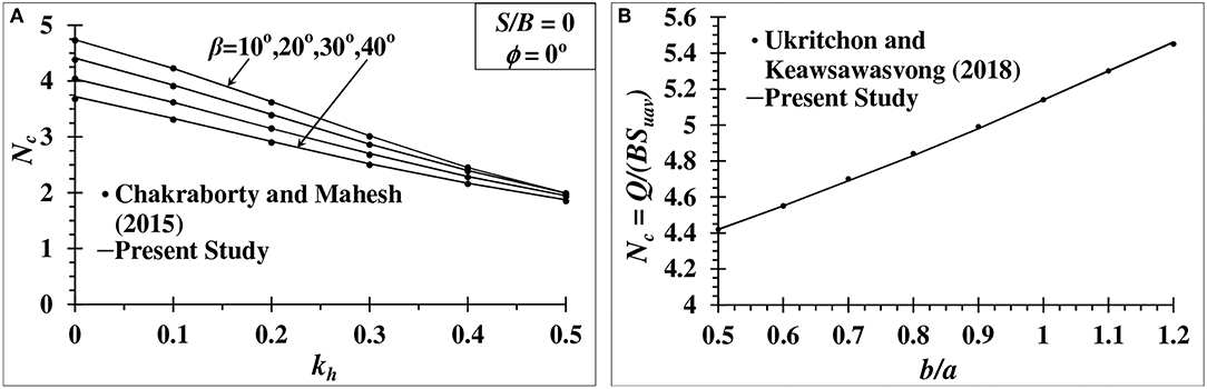
Figure 7. (A) Comparison of seismic bearing capacity factor Nc of Chakraborty and Mahesh (2015) and the present study for S/B = 0; (B) Comparison of Nc on an horizontal ground surface for different anisotropic strength ratio (b/a).
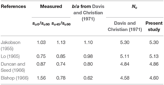
Table 1. Comparison of available experimental results with the present study.
By incorporating lower bound finite element limit analysis with second-order conic optimization technique, the seismic bearing capacity of a strip footing over an embankment of anisotropic clay is determined. The variation of bearing capacity factor Nc is presented as a function of slope angle (β), setback distance of footing (S), seismic coefficient (kh), and anisotropic strength ratio (b/a). Design charts are proposed based on the results of Nc. The design charts can be used by the practicing engineers to analyse the seismic bearing capacity of a strip footing over an embankment of anisotropic clay using the anisotropic strength ratio (b/a).
It is found that the bearing capacity factor Nc decreases with the increase in the value of β and kh. The trend of the reduction in the value of Nc with the increase in kh for a b/a value greater than or equal to one is almost linear. However, when b/a < 1, the trend of the reduction in the value of Nc becomes non-linear.
• It is also evident from the results that the influence of slope angle is higher for footings with lesser setback distances. When S value is reduced from 4B to 0B, for an embankment of β = 40°, b/a = 1.2 and kh = 0, there is 31.95% decrease in the Nc value; whereas, for β = 20°, the decrease is just 6.3%.
• The results show that there is larger reduction in the Nc values for b/a < 1 due to the fact that when b/a is lesser than 1, the minor axis (b) of elliptical yield surface becomes larger than the major axis(a), making the direction of anisotropy to change. For that reason, whenever the anisotropic strength ratio is lesser than 1, the strength reduces greatly.
• When anisotropic condition is coupled with earthquake force, the Nc values of strip footing situated over an embankment reduces drastically. Hence, more emphasis on anisotropy needs to be given while analyzing the seismic bearing capacity of strip footing over an embankment.
The datasets generated for this study are available on request to the corresponding author.
KK developed the codes in MATLAB for carrying out all the numerical simulations required in the present study and prepared the initial draft. KH and DC proposed the project. KH modified the initial draft. DC supervised all the works carried out in this project and given a final shape of the paper.
The authors declare that the research was conducted in the absence of any commercial or financial relationships that could be construed as a potential conflict of interest.
1. ^ABAQUS 6.14 [Computer software]. Dassault Systemes, Vélizy - Villacoublay.
2. ^MATLAB 8.5 [Computer software]. MathWorks, Massachussets, USA.
3. ^MOSEK ApS version 8.0 [Computer software]. MOSEK, Copenhagen, Denmark.
Bishop, A. W. (1966). The strength of soils as engineering materials. Geotechnique 16, 89–130. doi: 10.1680/geot.1966.16.2.91
Chakraborty, D., and Kumar, J. (2013). Bearing capacity of foundations on slopes. Geomech. Geoeng. 8, 274–285. doi: 10.1080/17486025.2013.770172
Chakraborty, D., and Kumar, J. (2015). Seismic bearing capacity of shallow embedded foundations on a sloping ground surface. Int. J. Geomech. 15:04014035. doi: 10.1061/(ASCE)GM.1943-5622.0000403
Chakraborty, D., and Mahesh, Y. (2015). Seismic bearing capacity factors for strip footings on an embankment by using lower-bound limit analysis. Int. J. Geomech. 16:06015008. doi: 10.1061/(ASCE)GM.1943-5622.0000553
Choudhury, D., and Subba Rao, K. S. (2006). Seismic bearing capacity of shallow strip footings embedded in slope. Int. J. Geomech. 6, 176–184. doi: 10.1061/(ASCE)1532-3641(2006)6:3(176)
Davis, E. H., and Christian, J. T. (1971). Bearing capacity of anisotropic cohesive soil. J. Soil Mech. Found. Div. 97, 753–769.
Duncan, J. M., and Seed, H. B. (1966). Strength variation along failure surfaces in clay. J. Soil Mech. Found. Div. 92, 21–50.
Georgiadis, K. (2009). Undrained bearing capacity of strip footings on slopes. J. Geotech. Geoenviron. Eng. 136, 677–685. doi: 10.1061/(ASCE)GT.1943-5606.0000269
Halder, K., and Chakraborty, D. (2018). Bearing capacity of strip footing placed on the reinforced soil slope. Int. J. Geomech. 18:06018025. doi: 10.1061/(ASCE)GM.1943-5622.0001278
Halder, K., and Chakraborty, D. (2019). Seismic bearing capacity of strip footing placed on the reinforced slope. Geosynth. Int. 26, 1–22. doi: 10.1680/jgein.19.00032
Halder, K., Chakraborty, D., and Dash, S. K. (2018). “Seismic bearing capacity of a strip footing situated on soil slope using a non-associated flow rule in lower bound limit analysis,” in Geotechnical Earthquake Engineering and Soil Dynamics V: Numerical Modeling and Soil Structure Interaction, Geotechnical Special Publication (American Society of Civil Engineers), 454–463.
Halder, K., Chakraborty, D., and Kumar Dash, S. (2019). Bearing capacity of a strip footing situated on soil slope using a non-associated flow rule in lower bound limit analysis. Int. J. Geotech. Eng. 13, 103–111. doi: 10.1080/19386362.2017.1325119
Kumar, J., and Chakraborty, D. (2013). Seismic bearing capacity of foundations on cohesionless slopes. J. Geotech. Geoenviron. Eng. 139, 1986–1993. doi: 10.1061/(ASCE)GT.1943-5606.0000909
Kumar, J., and Mohan Rao, V. B. K. (2003). Seismic bearing capacity of foundations on slopes. Geotechnique 53, 347–361. doi: 10.1680/geot.2003.53.3.347
Leshchinsky, B. (2015). Bearing capacity of footings placed adjacent to c′-φ′ slopes. J. Geotech. Geoenviron. Eng. 141:04015022. doi: 10.1061/(ASCE)GT.1943-5606.0001306
Raj, D., Singh, Y., and Shukla, S. K. (2018). Seismic bearing capacity of strip foundation embedded in c-φ soil slope. Int. J. Geomech. 18:04018076. doi: 10.1061/(ASCE)GM.1943-5622.0001194
Sloan, S. W. (1988). Lower bound limit analysis using finite elements and linear programming. Int. J. Numer. Analyt. Methods Geomech. 12, 61–77. doi: 10.1002/nag.1610120105
Terzaghi, K. (1943). Theoretical Soil Mechanics. New York, NY: John Wiley & Sons. doi: 10.1002/9780470172766
Ukritchon, B., and Keawsawasvong, S. (2018). Lower bound limit analysis of an anisotropic undrained strength criterion using second order cone programming. Int. J. Numer. Analyt. Methods Geomech. 42, 1016–1033. doi: 10.1002/nag.2781
Yang, X. L. (2009). Seismic bearing capacity of a strip footing on rock slopes. Can. Geotech. J. 46, 943–954. doi: 10.1139/T09-038
Keywords: seismic bearing capacity, embankment, lower bound limit analysis, non-linear optimization, clay anisotropy
Citation: Krishnan K, Halder K and Chakraborty D (2019) Seismic Bearing Capacity of a Strip Footing Over an Embankment of Anisotropic Clay. Front. Built Environ. 5:134. doi: 10.3389/fbuil.2019.00134
Received: 29 June 2019; Accepted: 31 October 2019;
Published: 15 November 2019.
Edited by:
Sanjay Shrawan Nimbalkar, University of Technology Sydney, AustraliaReviewed by:
Subhadeep Banerjee, Indian Institute of Technology Madras, IndiaCopyright © 2019 Krishnan, Halder and Chakraborty. This is an open-access article distributed under the terms of the Creative Commons Attribution License (CC BY). The use, distribution or reproduction in other forums is permitted, provided the original author(s) and the copyright owner(s) are credited and that the original publication in this journal is cited, in accordance with accepted academic practice. No use, distribution or reproduction is permitted which does not comply with these terms.
*Correspondence: Debarghya Chakraborty, ZGViYXJnaHlhQGNpdmlsLmlpdGtncC5hYy5pbg==
Disclaimer: All claims expressed in this article are solely those of the authors and do not necessarily represent those of their affiliated organizations, or those of the publisher, the editors and the reviewers. Any product that may be evaluated in this article or claim that may be made by its manufacturer is not guaranteed or endorsed by the publisher.
Research integrity at Frontiers
Learn more about the work of our research integrity team to safeguard the quality of each article we publish.