
94% of researchers rate our articles as excellent or good
Learn more about the work of our research integrity team to safeguard the quality of each article we publish.
Find out more
ORIGINAL RESEARCH article
Front. Built Environ., 20 September 2019
Sec. Earthquake Engineering
Volume 5 - 2019 | https://doi.org/10.3389/fbuil.2019.00112
This article is part of the Research TopicSeismic Analysis and Retrofitting of Historical BuildingsView all 14 articles
This paper presents an assessment of the capacity and enhancement of the seismic performance of a historical masonry structure in Plomari, a town on the south coast of Lesbos island in Greece. Owing to uncertainties regarding the properties of the material and the effectiveness of the members in providing lateral resistance, the study was particularly challenging. In addition, the fact that the structure consisted of a variety of structural element types, e.g., unreinforced masonry from natural stones, timber-framed masonry (with burned clay masonry units), and timber girders, while lacking horizontal diaphragms, introduced complexities to the response of the structure in both directions. In the design of the retrofit, the need to preserve the building's architectural and historical value by minimizing interventions posed several problems. To solve them, conventional as well as state-of-the-art strengthening methods are proposed. Moreover, the procedures of these methods are in accordance with the Greek seismic design code of 1959 and European standards (Eurocodes) related to earthquake-resistant masonry as well as guidelines for the design of timber and reinforced concrete. Seismic analyses of the structure were carried out with two different methods (statically applied load and time history analysis) for comparison. The results verify the improvement in its behavior in response to earthquakes as a result of the proposed strengthening methods.
Assessment of the seismic performance of historical buildings is an important subject owing to the risk of casualties as well as the potential impact on culture and the economy in case of a global or partial collapse. Therefore, to preserve such structures, the prevention of extended damage during earthquakes is necessary. State-of-the-art assessment methods of historic buildings can be found in the literature. More specifically Boscato et al. (2010) employed dynamic monitoring in order to assess the structural behavior of Rialto Bridge in Venice. Moreover, advanced assessment techniques like ground penetrating radar and endoscopic test were employed by Boscato et al. (2014) and Sciarretta et al. (2018) and in order to investigate the medieval façades of Palazzo Ducale in Venice.
The building examined in this study was built in the first half of the nineteenth century. It is a traditional mansion that is an exemplar of Greek heritage, and has been declared a protected monument—building (listed as protected—heritage structure) by the Greek Government. Similarly, as emphasized in previous studies of the restoration of traditional buildings (Maraveas et al., 2015), the preservation of the traditional architectural characteristics is of paramount importance in these projects. All retrofitting solutions thus need to ensure the preservation of the external and internal appearance of the building.
This study proposes the structural restoration of the historical masonry structure described above. First, a reliable assessment of its load-carrying capacity is performed and used to create a finite element model with the aid of the Robot Structural Analysis software (Autodesk Robot Structural Analysis Professional, 2016) in order to assess static and seismic demands on the various elements of the structure. Furthermore, a realistic simulation of the mechanical properties is crucial for minimizing uncertainties in the properties of the material. Accurate modeling of the geometry of the building and the analyses employed led to the identification of structural deficiencies. More importantly, the results of analyses of the simulated damage were compared with the actual damage recorded on a visit to the site. Strengthening solutions based on non-destructive methods are proposed. Finally, the effectiveness of these solutions is evaluated.
Scope of this study is to show the effectiveness of rigid diaphragms on the improvement of the performance of masonry structures under earthquake loading for various safety levels. Furthermore, this study shows that simplified linear analysis can give realistic—even conservative—results and advanced analysis methods (Syrmakezis et al., 1995; Asteris et al., 2005; Kyriakides et al., 2016, 2018; Caddemi et al., 2017; Casamassima and D'Amato, 2019), as well as advanced material models (Asteris et al., 2005, 2014; Asteris and Giannopoulos, 2012; Apostolopoulou et al., 2017) are not always needed, as they require extensive experimental investigations (Chronopoulos et al., 2012; Lysandrou et al., 2017) and time consuming analysis validation (Asteris et al., 2017, 2019).
An earthquake measuring 6.3 on the Richter scale struck under the sea between the islands of Lesbos and Chios in the East Aegean Sea on June 12, 2017, with tremors felt as far as Istanbul and Athens (BBC website, 2017). The epicenter of the earthquake was 5 km south of Plomari and had a focal depth of 10 km. Several buildings were damaged by the earthquake; in addition, the major road from the island's capital, Mytilene, to Plomari was damaged by a landslide. In the village of Vrisa, ~25 km northeast of Plomari, 10 people were taken to hospital with injuries due to the earthquake. Figure 1 (Lekkas et al., 2017) shows several buildings in Plomari that were severely damaged under the induced seismic loads.
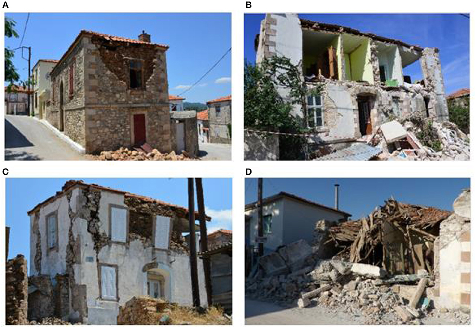
Figure 1. Typical damage to unreinforced masonry buildings that underwent partial or global collapse during the 2017 Lesvos earthquake (Lekkas et al., 2017; Reproduced with the permission of the authors). (A) The masonry failed under out-of-plane bending due to lack of a rigid diaphragm at the top. (B) The longitudinal masonry walls failed under out-of-plane bending due to their poor connection to the transverse walls. (C,D) Failures attributed to poor material properties and construction techniques.
The building studied covered an area of ~160 m2, and had a rectangular layout with approximate dimensions of 18.5 × 8.5 m; therefore, the walls along one of the main directions were nearly two times longer than those in the other main direction. Therefore, lateral stiffness and mass were not symmetrically distributed. The building had three floors with heights of 2.9, 5.75, and 4.7 m with a roof 1.4 m high. Owing to the architectural requirement of daylighting, each wall consisted of several large openings with dimensions of 1.2–1.5 × 1.2–4.2 m, occupying ~45% of the surface of each wall. This, of course, reduced the strength of the walls. Their thickness varied from 0.50 m at the top to 0.80 m at the base. Photographs of the exterior of the building (façade) are shown in Figures 2A,B while a typical plan of the building is presented in Figure 2C.
As is the case for most historical structures, sufficient information on the properties of the materials of the present masonry building was not available. Hence, tests were conducted by the contractor on samples taken from different locations of the building to assess the mechanical properties of the materials. More specifically, as shown in Figure 3A, six cylindrical masonry samples (see Figures 3B,C) were extracted from different locations and levels of the building which were then taken to the lab and subjected to monoaxial compression test. Three of these samples were also employed in order to estimate the compressive strength of the mortar. In addition to the laboratory tests, 12 Schmidt hammer tests were performed (their locations was not recorded) as well as four ultrasonic tests with their location presented in Figure 3A. A similar approach was used by Maraveas and Tasiouli (2015). Six core samples were extracted from various locations of the building's ground floor.
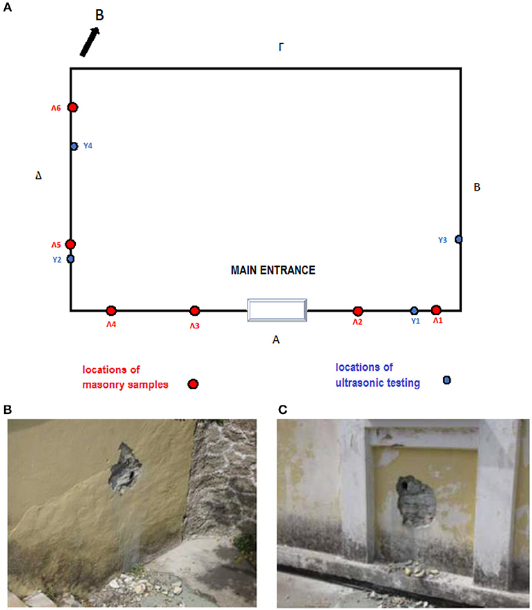
Figure 3. (A) Plan view with the locations where masonry samples were extracted (red colored) and ultrasonic testing was performed (blue coloreed), (B) masonry sample Λ1, (C) masonry sample Λ3.
The results of the aforementioned tests are summarized in Table 1 accompanied with the calculation of the average value and standard deviation of each testing. Specifically, the normalized mean compressive strength of the units in the direction of the applied action, f b, and the compressive strength of the mortar, f m, were defined as 43 and 1.19 MPa, respectively. Once these two properties have been obtained, the characteristic compressive strength, f k and shear strength of masonry, f νk0 can be easily calculated through equations provided in EN 1996-1-1 (2005).
Note that the tests characterized the mortar as weak. However, it should be mentioned that in some cases of historical masonry buildings, the equations described in EN 1996-1-1 (2005) may not be applicable due to peculiar block arrangement, aging etc. In this study, the state of the masonry blocks and mortar allowed the use of the provided in EN 1996-1-1 (2005).
Similarly to most historical structures, the timber floors and roof of the masonry building were assumed to be inadequate to act as diaphragms. This mainly a matter of poor connection between the floor and the walls. This connection is rather difficult to be achieved since the huge lateral stiffness of the masonry walls makes the in-plane stiffness of the floor insignificant. The walls were thus not expected to have effective lateral support perpendicular to the applied seismic load. That is, there was not adequate support to distribute the horizontal forces to the walls parallel to them; as a result, the walls experienced an excessive out-of-plane response.
A discussion of some critical aspects related to the effect of the diaphragm on the seismic behavior of masonry buildings can be found in Simsir et al. (2001) and Langroudi et al. (2011). Figures 4A,B illustrate the contribution of floor diaphragms to the flow of forces in unreinforced masonry buildings and the damage to these buildings without diaphragms, respectively.
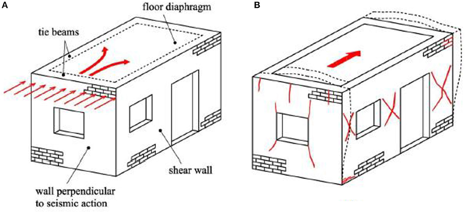
Figure 4. (A) Flow of forces in an unreinforced masonry building with rigid diaphragm. (B) Failure mechanisms to be considered when rigid diaphragm is absent (Tomaževič, 1999; Reproduced with the permission of the authors).
The key weakness of the unreinforced masonry member is its behavior under bending due to its inability to resist tension. Furthermore, it is widely recognized that unreinforced masonry leads to a brittle structure that fails when the maximum applied actions exceed the strength of the system. In the event of failure under shear, the masonry walls exhibit limited capacity for energy dissipation, especially when subjected to high compression stresses that are typical when the walls are heavy (Tomaževič, 1999).
The existence of timber elements (timber members supporting steel members under window bite) with masonry infills further complicates the seismic assessment of the examined structure. It is typical of historical buildings that the connections between timber elements and unreinforced masonry are weak (lack of shear connection), which leads to the separation of single parts from the rest of the building and causes them to behave as independent structural elements (Gabellieri et al., 2012). The seismic behavior of timber walls with masonry infills is a complex topic in earthquake engineering. The most important parameter of the seismic response of such structures is the connection between the different materials (Dutu et al., 2017). Even in cases where the interaction between timber and masonry is limited, overall seismic behavior improves. The timber carries the horizontal forces induced by the earthquake while the masonry carries mainly the gravitational loads, also dissipating energy through joints sliding after the cracking of mortar (Dutu et al., 2012). As shown in Figures 5A–D, the connection between the timber frames and the masonry is practically absent, leading to damage in specific regions under seismic loads.
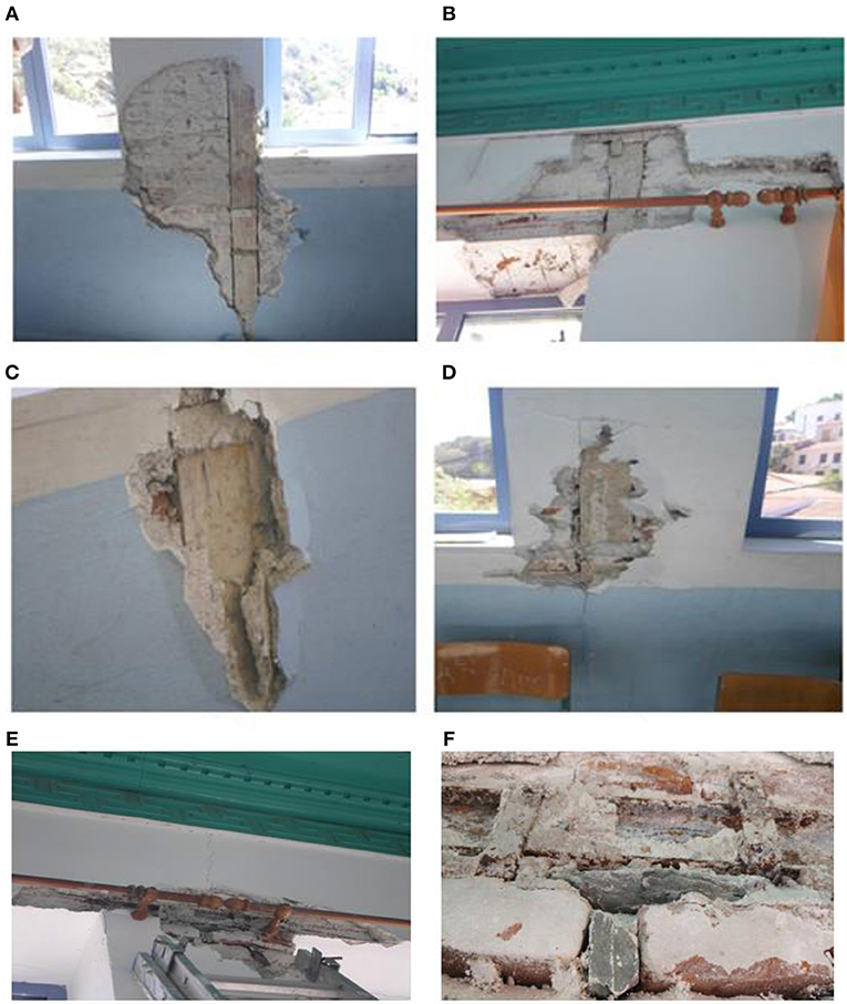
Figure 5. (A–D) Damages indicating weak connections between timber frames and masonry. (E,F) Damages attributed to weak mortar and the presence of voids inside the masonry panels.
Moreover, as shown in Figures 5E,F, damage during the 2017 earthquake revealed cracks inside the masonry, which verifies the characterization of mortar as weak during the laboratory tests.
The First Greek Seismic Code (Royal Decree on the Seismic Code for Building Structures, 1959) was initially implemented to assess the seismic response of buildings. According to this code, seismic loads can be applied horizontally to the center of mass of each floor, and are proportional to the total vertical load of the floor. The constant of this proportionality depends on the seismic zone and type of soil, and it was calculated 0.12. The total horizontal load at the top of each floor is divided by the number of nodes at the respective level and applied as the concentrated force at each node. Subsequently, on the basis of EN 1998-1-1 (2003), an inelastic response spectrum was adopted for soil type C (soil factor S = 1.15 and characteristic response spectrum periods TB = 0.2 s, TC = 0.6 s, and TD = 2.0 s), design ground acceleration ag = 0.24 g, importance factor γI = 1.20, and behavior factor q = 1.50. Finally, dynamic time history analysis was employed based on three accelerograms. For each of the abovementioned analyses, design checks according to EN 1996-1-1 (2005) were performed on the masonry members.
In addition to the weight of the structure itself, distributed dead loads of 0.5 and 1.0 kN/m2 were considered for the floors and the roof, respectively. The live load of the floor was 3.0 kN/m2. The abovementioned values are proposed by the Greek Loading Code (1945). Similarly to the approach used for the assignment of horizontal loads to the structure, vertical loads were applied as nodal forces.
The performed analyses were linear in terms of both material and displacements. In case of masonry buildings, shell elements are necessary to effectively capture the in-plane and out-of-plane bending of walls because they account for flexural deformation in addition to membrane forces. In this study, 4-noded shell elements were employed with 0.50 m thickness, a Young's Modulus, E, of 6,610 MPa and a Poisson's ratio, ν, of 0.30. A sensitivity analysis was also performed to define the finite element mesh size. In Figure 6, a 3D view of the model along with the meshing consisting of shell elements is presented. In regard to the boundary conditions at the ground level, fixed connections were considered in depth of 1.5 m as the foundation is deep. After sensitivity analysis, of fixed boundary conditions at −1.5 m and hinged at 0.00 m, it has been found that the results were the same (except of local stresses at supports). As shown in Figure 6, the timber roof was not included in the model because the connection between the roof and the masonry structure was considered weak, thus making interaction unlikely. Moreover, the timber-framed masonry elements were conservatively considered as unreinforced masonry elements.
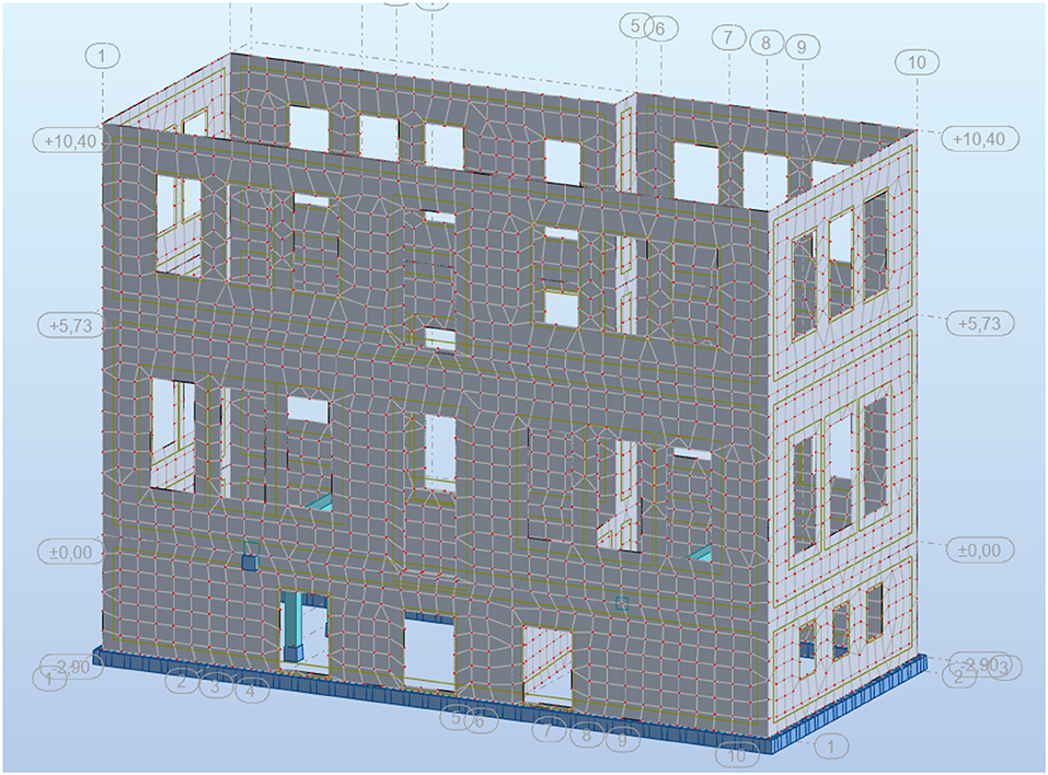
Figure 6. Finite element model in Robot Structural Analysis software (Autodesk Robot Structural Analysis Professional, 2016).
The results of the analysis were validated by comparison with damage recorded during a visit to the site. Figure 7 shows the results for seismic forces acting in the y direction according to the First Greek Seismic Code (Royal Decree on the Seismic Code for Building Structures, 1959), while Figure 8 show some damage recorded at the site. The stress concentrations of Figure 7 match the recorded damages in Figure 8, and are indicated by circles or ellipses of varying color. Specifically, the black circles indicate stress concentrations at the corners of the openings for walls parallel to the seismic action and the associated damage at those regions, green ellipses highlight stress concentrations approximately at the middle of the walls perpendicular to the seismic action (out-of-plane behavior) and the resulting cracks in masonry, and brown ellipses indicate the different behaviors of intersecting walls, where one of them was under tensile and the other under compressive stresses, and the associated vertical crack was at the intersection of the walls.
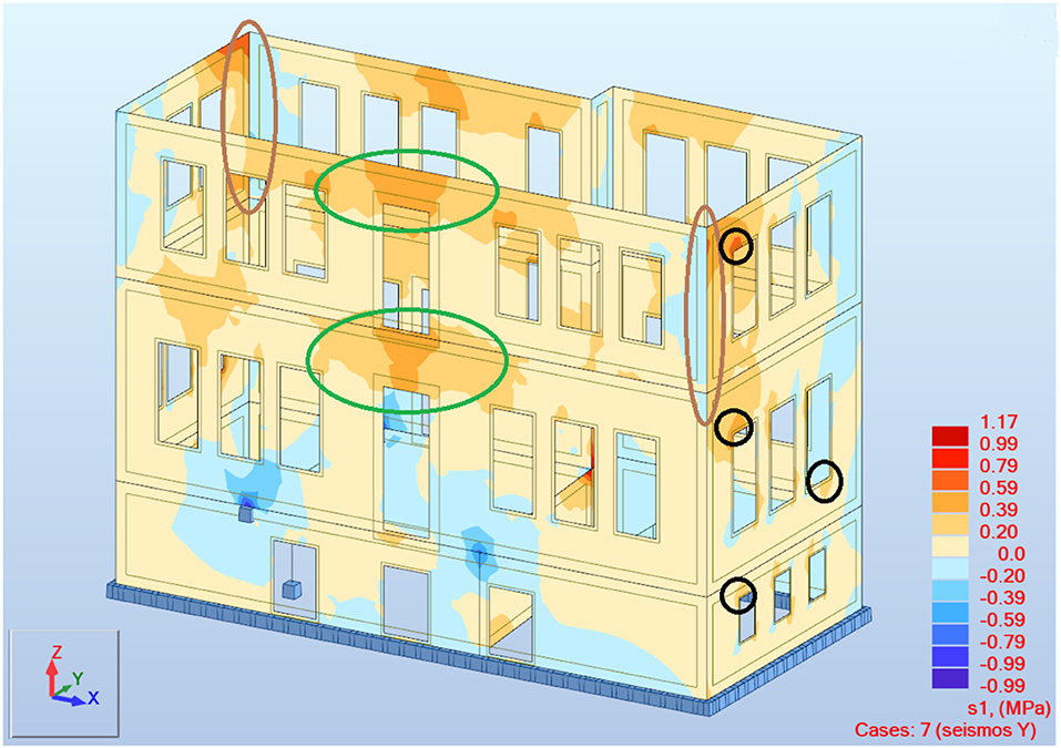
Figure 7. Results of principal stresses (MPa) for seismic action in the y direction according to the First Greek Seismic Code (Royal Decree on the Seismic Code for Building Structures, 1959).
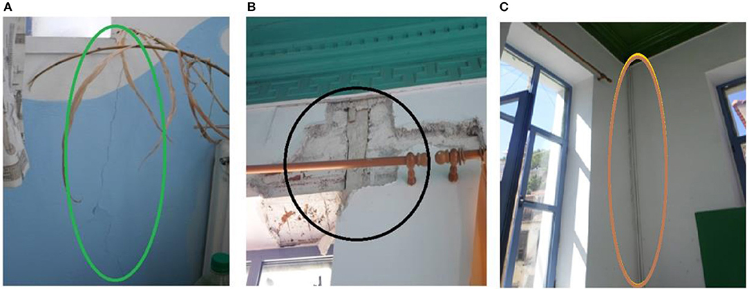
Figure 8. Damages recorded during the site visit. (A) Crack due to out of plane bending of the masonry wall. (B) Stress concentration under in plane bending of the masonry wall. (C) Crack attributed to poor connection between the intersecting walls.
A spectral analysis of modal response should be preceded by a modal analysis as this can be an issue in masonry buildings. In reinforced concrete and steel structures, it is reasonable to assume that the total weight of the floor is at the center of the slab. Moreover, the modeling of such structures with beam elements is usually sufficient to capture the structural response, while the existence of slabs provides diaphragm action. This leads to a uniform response of the structural members that constitute the building. As a result, in modal analysis of buildings such as the one considered in the present study, only a few modes are usually sufficient for mobilizing 90% of the total mass in lateral translation.
The above does not apply to masonry buildings with flexible diaphragms or no diaphragm at all, where the largest part of the total weight is distributed on the walls and realistic modeling of their response requires the use of shell elements, which results in more degrees of freedom than in a model consisting of beam elements. As noted in a study by Pantazopoulou (2013), the total number of degrees of freedom in the structure significantly affects the number of modes generated during modal analysis. As mentioned in the same study (Pantazopoulou, 2013), in case of masonry buildings with flexible diaphragms or no diaphragm at all, several hundred modes are sometimes needed for the modal analysis to mobilize as much as 70% of the total mass in lateral translation. In this study, more than 100 modes were used so that an effective modal mass equal to 90% of the total mass could be activated. Table 2 presents the results of the modal analysis which verify the abovementioned studies. As it can be seen, 124 modes were required in order for the activation of the 90% of the total mass criterion to be satisfied in both orthogonal directions.
Similarly to previous studies on the restoration of traditional buildings (Maraveas et al., 2014), seismic action was examined in terms of the time histories of ground accelerations for comparison. To this end, recordings of accelerations during three earthquake events (Loma Prieta, 1989; Northridge, 1994; Kocaeli, 1999) provided by the SeismoMatch software were considered (SeismoMatch, 2018). The original accelerograms were scaled using the software to adjust the ground motion records to the spectrum defined in the design code (target spectrum; Eurocode 8, 2003) using the wavelets' algorithm (Abrahamson, 1992; Hancock et al., 2006).
Although according to the literature (Oyarzo-Vera and Chouw, 2008), there is no uniform set of criteria for record scaling, EN 1998-1-1 (2003) suggests that artificial records be generated from the scaling of at least three real records.
From the time history analysis the most unfavorable time step considered.
Figures 9A,B present the response spectra of the initial records and the matched spectra, respectively, along with the target spectrum. The original (blue) and scaled (red) accelerograms corresponding to the employed seismic motions are presented in Figure 10.
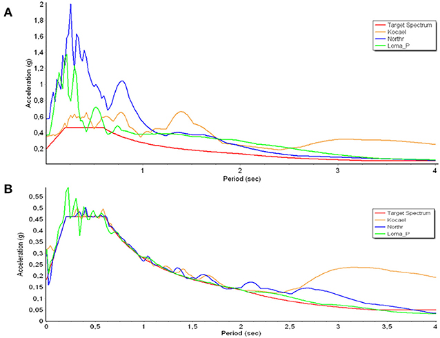
Figure 9. (A) Response spectra of the original accelerograms, and (B) response spectra of the matched accelerograms.
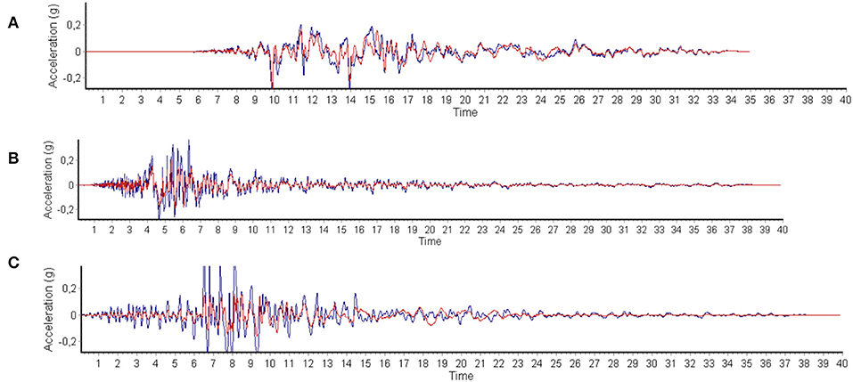
Figure 10. Time histories used for dynamic analyses: (A) Kocaeli (1999), (B) Northridge (1994), and (C) Loma Prieta (1989), with blue and red indicating the original and the scaled accelerograms, respectively.
The design resistances of unreinforced masonry according to EN 1996-1-1 (2005) were employed to check the results of the analyses, and are summarized below (Equations, 1–4):
The results of the modal response spectrum analysis indicated that the absence of rigid diaphragms at floor levels leads to serious damages. Its deformed shape under horizontal load was similar to that of a 10.5 m cantilever owing to the absence of a horizontal diaphragm. The stability of the unreinforced masonry could thus not be ensured because of a combination of large out-of-plane bending moments and slenderness ratios approximately equal to eight.
The most important step in the process of retrofitting a masonry building involves the elucidation of its pathology. Thus, the main goal of the retrofit was to restore the lateral stability of the walls. According to Fardis (2009), the aim of retrofitting is to modify the seismic demands Ed, and/or capacities, so that all relevant elements of the strengthened building satisfy the general verification inequality, Ed ≤ Rd, under the specified seismic action. This goal can be achieved by following one of the strategies below, or even a combination of them:
1. by reducing seismic demands on the members and the structure as a whole; and
2. by increasing the capacity of the members.
Bearing this in mind, the following retrofitting solutions are proposed:
a. Building rigid diaphragms at floor level. This method provides an effective way of distributing the horizontal forces induced by the earthquake to all masonry walls, thus diminishing the detrimental out-of-plane response of the walls perpendicular to the seismic action. Thus, the separation of the walls along the vertical joints and excessive cracking in general is expected to be resolved.
b. Repointing. As mentioned above, the mortar was found to be weak. Therefore, it was considered necessary to replace part of the existing mortar with mortar of significantly better quality, e.g., cement mortar.
c. Cement grouting. When the examined structure was built, the method of construction of unreinforced masonry usually led to the development of voids over their entire volume. Hence, filling the voids by injecting cementitious grout can be an adequate solution for retrofitting.
d. External bonding of timber members with masonry and improvement of shear connection.
Of the aforementioned retrofitting solutions, only (a) belongs to strategy 1, whereas (b), (c), and (d) belong to strategy 2. Another key parameter regarding methods of restoration is the preservation of characteristics of the traditional architecture. This requirement is assumed to be satisfied because it is clear that none of the abovementioned strengthening solutions affect the historical value and aesthetic appearance of the building. In the following section, solutions (a) and (d) are discussed because methods (b) and (c) are used frequently to improve the seismic performance of masonry piers.
For rigid diaphragm action, the boards of the timber floor were temporarily removed after being counted, and two plywood boards, each 10 mm thick, were placed in both orthogonal directions at the top of the timber joists. The removed boards were then placed exactly in their initial positions and the entire system was fastened together using wood screws (Figure 11A). A similar approach has been suggested by Tomaževič (1999), according to whom rigid horizontal diaphragm action is obtained by nailing boards in both orthogonal directions at the top of the timber joists. Of course, this method assumes that the timber joints are effectively connected to the walls through steel anchors. Therefore, holes should be bored to allow steel anchors to penetrate the walls and then be bolted to the timber joints. The holes are then filled with non-shrinking grout and the anchors are anchored at the external surface of the walls through steel plates. A schematic of this method is presented in Figure 11B.
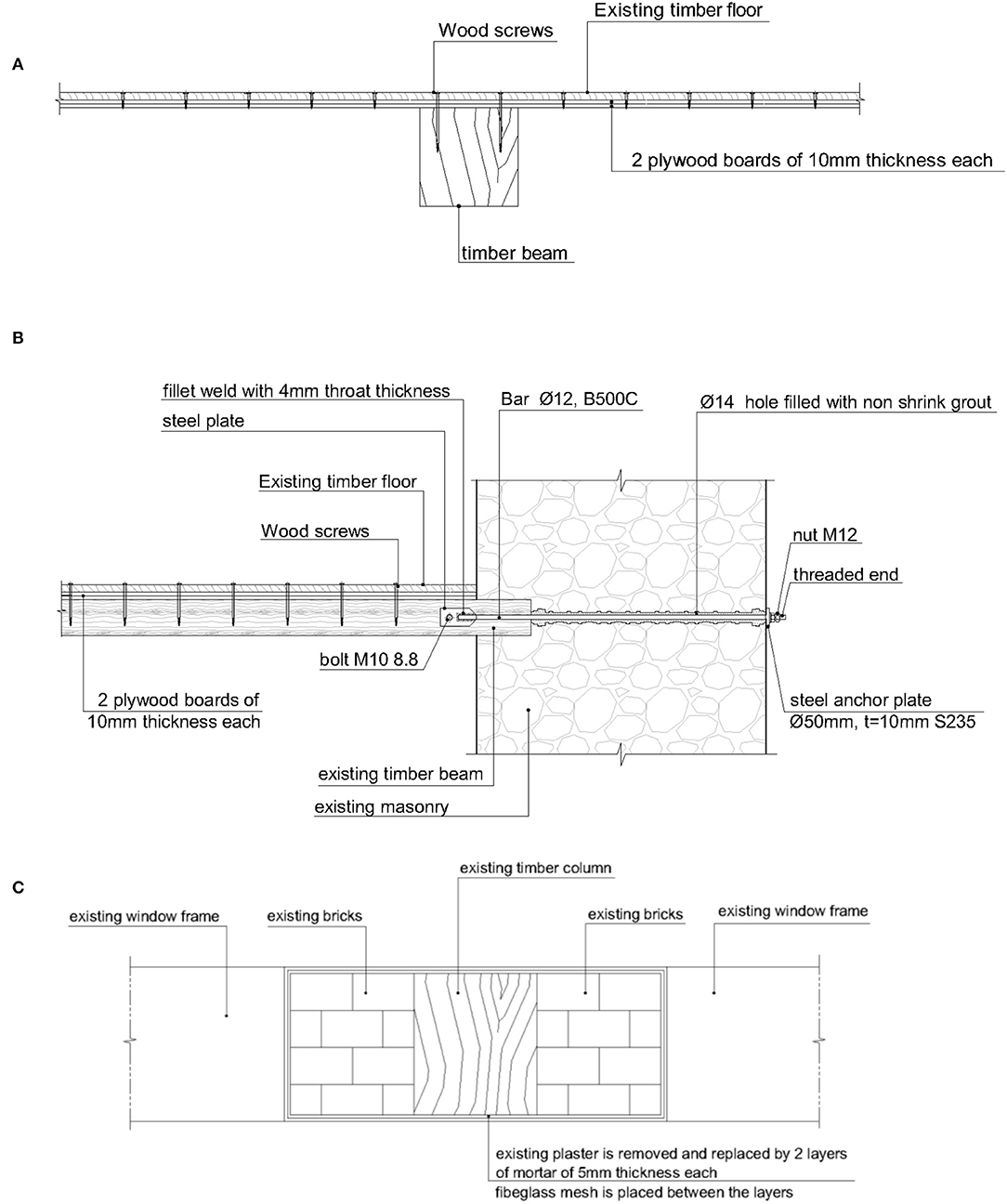
Figure 11. (A) Connection of rigid diaphragms to timber beams, (B) connection of timber beams to unreinforced masonry, and (C) external bonding of masonry infilled timber walls through TRM.
As described by Triantafillou (2016), the textile-reinforced mortar (TRM) system is an ideal retrofitting solution for connecting different structural members. Accordingly, this method was selected for bonding the masonry units with the adjacent timber elements.
The effectiveness of this method in comparison with similar strategies has been previously investigated in studies such as those by Papanicolaou et al. (2007) and Tetta et al. (2015), where a comparison between TRM and fiber-reinforced polymers (FRP) as strengthening material was drawn. This method was only implemented on panels between openings, for two reasons: first, these represent the positions where the related damage was detected; second, the application of the specific method, as detailed below, is much easier in such positions.
As shown in Figure 11C, to enhance the response of the specific elements, the existing plaster was removed and a first layer of mortar (5 mm thick) was placed. A fiberglass mesh was then installed and covered with a second 5-mm-thick mortar layer while the first layer was wet. The total thickness of the strengthening system was approximately the same as that of the initial plaster.
It must be noted that the effect of TRM has been considered in the analysis of the retrofitted model. The effect on the overall response was negligent, as the thickness of the TRM is just 1 cm, the Young's modulus is similar to masonry (for compatibility issues), and the retrofit was local, only around the windows of the A' floor level. So, the effect of TRM was considered mainly in terms of improved masonry capacity.
A schematic of the results (in terms of principal bending moments) of time history analyses for the initial and the retrofitted model (including diaphragms) is presented in Figures 12A,B, respectively. In the absence of diaphragms, the bending moments spread freely from the foundation to the top of the building, while for the strengthened model, the bending moments were limited to low values with the exception of walls of the top floor, which act as cantilevered walls.
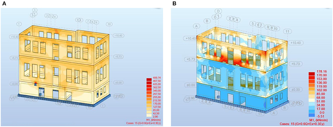
Figure 12. Comparison of the principal bending moments (kNm) from time history analyses for the initial (A) and the strengthened models (B).
Table 3 lists a comparison of various results obtained from the analysis of both the existing and the retrofitted structures. The results refer to the maximum bending moment, shear force, and top displacement on the structure.
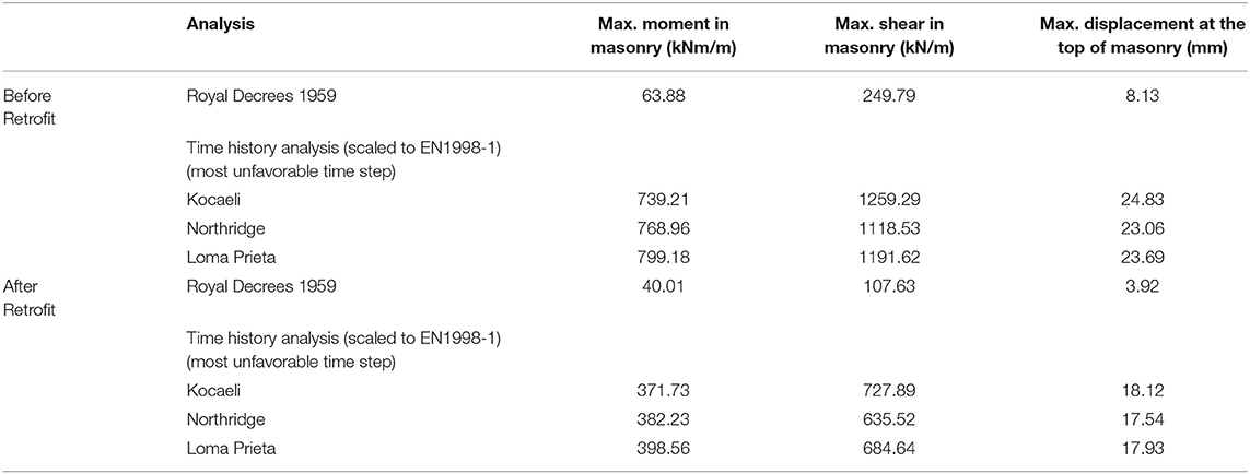
Table 3. Comparison of forces and displacements for the studied cases of seismic analysis, while moment capacity is of the range of 250 kN m/m and shear capacity is of the range of 120 kN/m (depends of the exact dimensions of each masonry unit).
In regard to the values under the “Before Retrofit” row, only those related to the Royal Decrees of 1959 satisfied the design checks provided by EN 1996-1-1 (2005) presented earlier (section Structural Evaluation of the Building) in this study. However, all values under the retrofitted section satisfied the same design checks.
It should additionally be noted that the modal frequencies of the retrofitted building were higher than those of the existing building owing to an increase in stiffness associated with the presence of floor diaphragms.
1. Comparison of the results revealed that the simpler method of analysis proposed in the first Seismic Greek Code (Royal Decree on the Seismic Code for Building Structures, 1959) may underestimate the seismic behavior of masonry buildings. The response spectrum analysis yielded the most unfavorable results, with dynamic time history analysis resulting in a slightly more favorable seismic response.
2. Although it has been stated that traditional lateral load-resisting systems were conceived to sustain seismic forces (Syrmakezis et al., 2005; Vintzileou et al., 2007), this seems to apply only to cases where the seismic response was evaluated based on previous design codes (Royal Decree on the Seismic Code for Building Structures, 1959). However, historical structures do not meet seismic demands specified in modern codes, especially in regions with high seismic activity.
3. The expected damage indicated by the present analyses seems to be in agreement with damage recorded during the visit to the site, thus validating the proposed finite element model and numerical analyses.
4. The introduction of rigid diaphragms led to the compliance of the structural performance with the old codes, which require lower safety levels than the modern codes. The key aspects of this method are that it is relatively cost-effective, reversible, and minimally alters the appearance of the building. If Eurocodes are applied, further retrofits and interventions are required.
5. In the absence of rigid diaphragms, stresses were mainly concentrated in the corners of openings for walls parallel to the seismic action and approximately at the middle of the walls perpendicular to the seismic action. However, once rigid diaphragms had been included in the analysis, the stresses were uniformly distributed on every wall irrespective of the direction of the seismic forces.
6. Not only did the maximal displacements reduce as a result of the effect of the diaphragm, but the difference in terms of maximal displacement between the orthogonal directions also decreased.
7. The base shear forces applied to the resisting elements were more uniformly distributed. Moreover, the diaphragms restricted the spread of stresses to within the height of each floor, while in the case where there was no diaphragm, the stresses spread freely from the foundation to the top of the building.
8. The above observations indicate that the introduction of rigid diaphragms led to a global improvement of structural response, which was characterized by the uniform behavior of the structural elements and better utilization of the material.
9. The presence of rigid diaphragms at the floor levels led to a decrease in the structure's fundamental period. Therefore, this retrofitting method can also have a beneficial effect in cases where the structure is founded on soft soils characterized by a long period by preventing dynamic amplifications generated by the resonance between the underlying soil layers and the superstructure. Conversely, this strengthening method should be selected carefully in cases where the structure is founded on firm soils, because a further decrease in the structure's fundamental period can lead to the tuning of the soil–structure system, with detrimental effects on its seismic performance.
All data generated or analyzed during this study are available by the author.
The author confirms being the sole contributor of this work and has approved it for publication.
The author declares that the research was conducted in the absence of any commercial or financial relationships that could be construed as a potential conflict of interest.
Apostolopoulou, M., Aggelakopoulou, E., Siouta, L., Bakolas, A., Douvika, M., Asteris, P. G., et al. (2017). A methodological approach for the selection of compatible and performable restoration mortars in seismic hazard areas. Constr. Build. Mater. 155, 1–14. doi: 10.1016/j.conbuildmat.2017.07.210
Asteris, P. G., Chronopoulos, M. P., Chrysostomou, C. Z., Varum, H., Plevris, V., Kyriakides, N., et al. (2014). Seismic vulnerability assessment of historical masonry structural systems. Eng. Struct. 62–63, 118–134. doi: 10.1016/j.engstruct.2014.01.031
Asteris, P. G., Douvika, M. G., Apostolopoulou, M., and Moropoulou, A. (2017). Seismic and restoration assessment of monumental masonry structures. Materials 10:895. doi: 10.3390/ma10080895
Asteris, P. G., and Giannopoulos, I. P. (2012). Vulnerability and restoration assessment of masonry structural systems. Electronic J. Struct. Eng. 12, 82–93.
Asteris, P. G., Moropoulou, A., Skentou, A. D., Apostolopoulou, M., Mohebkhah, A., Cavaleri, L., et al. (2019). Stochastic vulnerability assessment of masonry structures: concepts, modeling and restoration aspects. Appl. Sci. 9:243. doi: 10.3390/app9020243
Asteris, P. G., Tzamtzis, A. D., Vouthouni, P. P., and Sophianopoulos, D. S. (2005). Earthquake resistant design and rehabilitation of masonry historical structures. Pract. Period. Struct. Design Constr. 10, 49–55. doi: 10.1061/(ASCE)1084-0680(2005)10:1(49)
Autodesk Robot Structural Analysis Professional v.29.0 (2016). Available online at: https://www.autodesk.com/products/robot-structural-analysis/overview (accessed September 13, 2019).
BBC website (2017). Available online at: https://www.bbc.com/news/world-europe-40251100 (accessed September 13, 2019).
Boscato, G., Dal Cin, A., Riva, G., Russo, S., and Sciarretta, F. (2014). Knowledge of the construction technique of the multiple leaf masonry façades of Palazzo Ducale in Venice with ND and MD tests. Adv. Mater. Res. 919–921, 318–324. doi: 10.4028/www.scientific.net/AMR.919-921.318
Boscato, G., Di Tomasso, A., Guerra, F., Lazzarini, L., Mazzucato, A., Pizzolato, M., et al. (2010). “Approach and methodology in understanding the structural behaviour of historic arch bridges through dynamic monitoring: the case of Rialto Bridge in Venice,” in Proceedings of 34th IABSE Symposium (Venice).
Caddemi, S, Caliò, I, Cannizzaro, F, and Pantò, B. (2017). New frontiers on seismic modeling of masonry structures. Front. Built Environ. 3:39. doi: 10.3389/fbuil.2017.00039
Casamassima, V. M., and D'Amato, M. (2019). Fatigue assessment and deterioration effects on masonry elements: a review of numerical models and their application to a case study. Front. Built Environ. 5:65. doi: 10.3389/fbuil.2019.00065
Chronopoulos, P. M., Zigouris, N., and Asteris, P. G. (2012). “Investigation/documentation and aspects of seismic assesment and redesign of traditional masonry buildings in Greece,” in 5th European Conference on Structural Control (EACS 2012) (Genoa).
Dutu, A., Gomes- Ferreira, J., Goncalves, A. M., and Covaleov, A. (2012). Components interaction in timber framed masonry structures subjected to lateral forces. J. Civil Eng. Res. 13, 62–67.
Dutu, A., Sakata, H., and Yamazaki, Y. (2017). “Comparison between different types of connections and their influence on timber frames with masonry infill structures' seismic behavior,” in 16th Conference on Earthquake Engineering (Santiago).
EN 1996-1-1 (2005). Eurocode 6–Design of Masonry Structures–Part 1-1: General Rules for Reinforced and Unreinforced Masonry Structures. Brussels: CEN.
EN 1998-1-1 (2003). Eurocode 8–Design of Structures for Earthquake Resistance–Part 1: General Rules, Seismic Actions and Rules for Buildings. Brussels: CEN.
Fardis, M. N. (2009). Seismic Design, Assessment and Retrofitting of Concrete Buildings (Based on EN-Eurocode 8). Dordrecht: Springer Science + Business Media BV.
Gabellieri, R., Diotallevi, P. P., and Landi, L. (2012). E”ffect of diaphragm flexibility on the dynamic behaviour of unreinforced masonry walls in out-of-plane bending,” in 15th World Conference on Earthquake Engineering (15WCEE) (Lisbon).
Hancock, J., Watson-Lamprey, J., Abrahamson, N. A., Bommer, J. J., Markatis, A., McCoy, E., et al. (2006). An improved method of matching response spectra of recorded earthquake ground motion using wavelets. J. Earthquake Eng. 10, 67–89 doi: 10.1080/13632460609350629
Kyriakides, N., Illampas, R., Lysandrou, V., Agapiou, A., Masini, N., Sileo, M., et al. (2018). “Study of ancient monuments' seismic performance based on Passive and Remote Techniques,” in 16th European Conference on Earthquake Engineering (Thessaloniki).
Kyriakides, N., Lysandrou, V., Agapiou, A., Illampas, R., and Charalambous, E. (2016). Correlating damage condition with historical seismic activity in underground sepulchral monuments of Cyprus. J. Archaeol. Sci. Rep. 14, 734–741 doi: 10.1016/j.jasrep.2016.07.007
Langroudi, J., Ranjbar, M., Hashemi, S., and Moghadam, A. (2011). “Evaluation of roof diaphragm effect on seismic behavior of masonry buildings,” in Proceedings of 8th International Conference on Structural Dynamics (Leuven).
Lekkas, E., Voulgaris, N., Karydis, P., Tselentis, G. A, Skourtsos, E., Antoniou, B., et al. (2017). The Earthquake in Lesbos, Mw 6.3, 12th of June 2017 in (Greek). Athens: Newsletter.
Lysandrou, V., Agapiou, A., Kyriakides, N., and Hadjimitsis, D. G. (2017). F”rom space to ground. Digital techniques for the investigation of monuments and sites,” in 10th International Symposium on the Conservation of Monuments in the Mediterranean Basin (Athens). doi: 10.1007/978-3-319-78093-1_65
Maraveas, C., Miamis, K., Tasiouli, K., and Fasoulakis, Z. (2014). “Structural analysis and retrofitting of “Tzotza” building in Kastoria, Greece,” in 9th International Conference on Structural Analysis of Historical Construction (Mexico City).
Maraveas, C., and Tasiouli, K. (2015). Assessment and restoration of the first Greek power plant - registered monument of industrial heritage. Case Stud. Struct. Eng. 2, 1–10. doi: 10.1016/j.csse.2014.12.001
Maraveas, C., Tasiouli, K., and Fasoulakis, Z. (2015). “Assessment of the new Faliron steam–electric station in Greece,” in 14th International Conference on Studies, Repairs and Maintenance of Heritage Architecture (A Coruña), 247–259.
Oyarzo-Vera, C., and Chouw, N. (2008). “Comparison of record scaling methods proposed by standards currently applied in different countries,” in 14th World Conference on Earthquake Engineering (Beijing).
Pantazopoulou, S. J. (2013). State of the Art Report for the Analysis Methods for Unreinforced Masonry Heritage Structures and Monuments. European Centre on Prevention and Forecasting of Earthquakes (ECPFE).
Papanicolaou, C. G., Triantafillou, T. C., Karlos, K., and Papathanasiou, M. (2007). Textile-reinforced mortar (TRM) versus FRP as strengthening material of URM walls: in-plane cyclic loading. Mater. Struct. 40:1081. doi: 10.1617/s11527-006-9207-8
Royal Decree on the Seismic Code for Building Structures (1959). Government's Gazette, Issue A, No. 36, February, 1959, Greece in (Greek).
Sciarretta, F., Antonelli, F., Peron, F., and Caniglia, S. (2018). Final outcomes on the multi-disciplinary long-term monitoring and preservation state investigation on the medieval external Façades of Palazzo Ducale in Venice, Italy. J. Civil Struct. Health Monit. 8, 111–133. doi: 10.1007/s13349-017-0263-2
SeismoMatch v.2.1.0 (2018). Seismosoft. Available online at: www.seismosoft.com (accessed September 13, 2019).
Simsir, C., Aschheim, M., and Abrams, D. (2001). “Influence of diaphragm flexibility on the out-of-plane response of unreinforced masonry walls,” in Proc. 9th Canadian Masonry Symposium (Fredericton, NB).
Syrmakezis, C. A., Antonopoulos, A. K., and Mavrouli, O. A. (2005). “Historical structures' vulnerability evaluation using fragility curves,” in Proceedings of 10th International Conference on Civil, Structural and Environmental Engineering Computing (Rome).
Syrmakezis, C. A., Chronopoulos, M. P., Sophocleous, A. A., and Asteris, P.G. (1995). “Structural analysis methodology for historical buildings,” in Proceedings, Fourth International Conference on Structural Studies of Historical Buildings, STREMA 95, Vol. 1 (Crete), 373–382.
Tetta, Z. C., Koutas, L. N., and Bournas, D. A. (2015). Textile-reinforced mortar (TRM) versus fiber-reinforced polymers (FRP) in shear strengthening of concrete beams. Compos. B Eng. 77, 338–348. doi: 10.1016/j.compositesb.2015.03.055
Triantafillou, T. (2016). Strengthening of existing masonry structures: concepts and structural behavior. Text. Fibre Composites Civil Eng. 361–374. doi: 10.1016/B978-1-78242-446-8.00016-1
Vintzileou, E., Zagkotsis, A., Repapis, C., and Zeris, C. (2007). Seismic behaviour of the historical structural system of the island of Lefkada, Greece. Constr. Build. Mater. 21, 225–236. doi: 10.1016/j.conbuildmat.2005.04.002
Keywords: historical structures, masonry, earthquake resistance, strengthening, restoration, retrofit, rigid diaphragm
Citation: Maraveas C (2019) Assessment and Restoration of an Earthquake-Damaged Historical Masonry Building. Front. Built Environ. 5:112. doi: 10.3389/fbuil.2019.00112
Received: 25 May 2019; Accepted: 09 September 2019;
Published: 20 September 2019.
Edited by:
Panagiotis G. Asteris, School of Pedagogical and Technological Education, GreeceReviewed by:
Francesca Sciarretta, Università Iuav di Venezia, ItalyCopyright © 2019 Maraveas. This is an open-access article distributed under the terms of the Creative Commons Attribution License (CC BY). The use, distribution or reproduction in other forums is permitted, provided the original author(s) and the copyright owner(s) are credited and that the original publication in this journal is cited, in accordance with accepted academic practice. No use, distribution or reproduction is permitted which does not comply with these terms.
*Correspondence: Chrysanthos Maraveas, Yy5tYXJhdmVhc0BtYXJhdmVhcy5ncg==
Disclaimer: All claims expressed in this article are solely those of the authors and do not necessarily represent those of their affiliated organizations, or those of the publisher, the editors and the reviewers. Any product that may be evaluated in this article or claim that may be made by its manufacturer is not guaranteed or endorsed by the publisher.
Research integrity at Frontiers

Learn more about the work of our research integrity team to safeguard the quality of each article we publish.