
95% of researchers rate our articles as excellent or good
Learn more about the work of our research integrity team to safeguard the quality of each article we publish.
Find out more
ORIGINAL RESEARCH article
Front. Built Environ. , 08 August 2019
Sec. Sustainable Design and Construction
Volume 5 - 2019 | https://doi.org/10.3389/fbuil.2019.00097
 Mohamed Hamdy1*
 Gerardo Maria Mauro2
Optimal ventilation strategies are fundamental to achieve net/nearly-zero energy buildings. In this study, three hybrid ventilation control strategies are proposed to minimize the cooling need in an open-plan office building, located in the center of Glasgow (Scotland). The performance of the three proposals is assessed by IDA ICE (a whole building performance simulation tool) and compared to a traditional fully mechanical ventilation system. The performance comparison includes different criteria, i.e., indoor temperature and predicted percentage of dissatisfied (PPD) for assessing the indoor comfort, and CO2 level for assessing the indoor air quality (IAQ). The results show that the three proposed hybrid ventilation strategies are able to minimize the cooling need to zero. They can also imply a drastic reduction of AHU heating power, compared with a mechanical ventilation system without heat recovery (or with low efficiency heat recovery). In addition, they significantly save the fan energy. The only drawback of the proposed strategies is that they might increase space heating demand. For instance, the first and second strategies save about 75 and 50% of AHU (air handling unit) fan energy; however, the space heating increases by about 4.2 and 2.2 kWh/m2a, respectively. The third strategy features as the best proposal because it saves around 68% of fan energy with less increase (1.3 kWh/m2a) in heating demand. Moreover, it ensures higher thermal comfort and IAQ levels compared to the first and second proposals.
In cold and moderate climates, different approaches of natural cooling-ventilation systems can be used for low-energy buildings, such as simple natural ventilation by opening windows, natural ventilation with a control strategy, mechanical ventilation, combined natural and mechanical ventilation (hybrid ventilation). For instance, Hamdy et al. (2009) employed IDA-ICE (2002) to investigate a house building in cold climate of Finland by implementing a simple window-opening control strategy for summer cooling. Tuohy et al. (2007) proposed the implementation of the standard EN15251 adaptive comfort criteria as well as of the Humphreys window opening behavioral algorithm under ESP-r environment for the analysis of summer overheating in an office in the UK. Definitely, combined natural and mechanical ventilation (hybrid ventilation) can provide significant benefits concerning thermal comfort, Indoor Air Quality (IAQ), and energy (cooling/heating and fan energy) needs compared to traditional ventilation systems. In this regard, natural ventilation is an effective measure to cool down indoor environments during summer as well as to improve the IAQ. It can be implemented by means of different strategies, such as stack induced ventilation and cross-section ventilation (Mahdavi and Pröglhöf, 2008; Emmerich et al., 2011). Furthermore, it ensures high effectiveness in most climate types, especially when it is applied during nighttime (i.e., night ventilation) in order to reduce building cooling demand (Solgi et al., 2018). Therefore, natural ventilation represents one of the most promising passive strategies to achieve high performance buildings and to enhance thermal comfort and IAQ (Wang and Malkawi, 2019). In this regard, in order to quantify the thermal and energy benefits of natural ventilation, Wang and Malkawi (2019) proposed a new index, denoted as Design-Based Natural Ventilation Potential, which can provide useful guidelines in early design stage for high performance naturally ventilated buildings. Nevertheless, natural ventilation has different limitations. For instance, it is difficult to be rigorously controlled and its effectiveness highly depends on wind velocity, as well as on the characteristics of outdoor air in terms of temperature, humidity and level of pollution. Morevoer, natural ventilation needs a robust design optimization in order to ensure energy savings and thermal comfort (Solgi et al., 2018; Yang et al., 2019), and in some cases, it can provide higher ventilation rates compared to mechanical ventilation, which can raise the issue if increased indoor pollutant concentration (e.g., PM2.5, PM10 and ozone) from outdoor sources in polluted urban or industrial areas (Chen et al., 2019). On the other hand, mechanical ventilation causes an increase of building energy needs. Therefore, hybrid ventilation, which is the combination between natural and mechanical ventilation, represents a worthy strategy to achieve energy efficiency, thermal comfort, and satisfying IAQ (Yoshino et al., 2003; Tovar et al., 2007). Indeed, buildings equipped with hybrid ventilation systems can achieve significant reductions of energy needs and CO2 levels compared with conventional air conditioning designs (Fu and Wu, 2015). Different hybrid ventilation control strategies can be found in several studies. Yao et al. (2009) investigated the feasibility of this technique for Chinese buildings showing significant cooling potentials despite of the more complex design compared to conventional ventilation systems. In the same vein, Ji et al. (2009) addressed a low energy building design in Hangzhou (south China) showing that hybrid ventilation is a viable and low energy measure for design optimization, even in sub-tropical climates. Calay and Wang (2013) proposed a highly efficient hybrid ventilation system, which uses waste energy from the exhaust air stream to precondition ventilation air, providing heating in wintertime and cooling in summertime without compromising the IAQ and ensuring energy savings up to 60%. Ezzeldin and Rees (2013) examined the potentials of hybrid ventilation for a single floor office building in an arid climate. They showed energy savings over 50% compared to a fully air-conditioned building. In the same vein, Spindler and Norford (2009) investigated a similar office building in U.S.A. climates—analyzing more than 50 cities—and concluded that hybrid ventilation can provide energy savings between 2 and 30% depending on the climate. Similarly, Chen et al. (2018) assessed the potential energy savings produced by hybrid ventilation for small to medium sized office buildings with different intelligent controls in U.S.A. climates, achieving savings between 10 and 50%. Concerning U.S.A. climates too, Emmerich (2006) demonstrated that hybrid ventilation can ensure high levels of IAQ and thermal comfort in commercial buildings. Furthermore, Menassa et al. (2013a,b) investigated the feasibility and effectiveness of hybrid ventilation systems in complex buildings, such as hospitals, which require significant ventilation loads and therefore the optimization of ventilation systems offers substantial potential energy savings. The authors employed an experimental approach and linear regression to examine different hybrid ventilation strategies in public areas of a laboratory building located in Madison–Wisconsin (U.S.A). The optimized hybrid ventilation strategy ensured 56% savings of ventilation and cooling loads (Menassa et al., 2013a). Furthermore, the authors developed an automated control of the ventilation system, which enabled hybrid ventilation to be used through 28% of the cooling season days, resulting in 20% energy savings compared to traditional mechanical ventilation (Menassa et al., 2013b). Lim et al. (2015) investigated a hybrid ventilation system mounted at a window, which ensured—fixing the IAQ level—energy savings up to 41.3% depending on the control type. Yang and Li (2015) applied a dimensionless design approach to investigate energy performance and effectiveness of stack-based hybrid ventilation for multi-story buildings. The approach was validated by comparison with numerical simulations, and allowed to optimize the interface between NVFs (naturally ventilated floors) MVFs (mechanically ventilated floors) as well as the vent sizes of NVFs, ensuring a proper trade-off among ventilation flow rates, indoor temperatures and heat inputs. Similarly, Hurnik et al. (2017) investigated a stack-based hybrid ventilation for a two-story single-family house. In particular, the proposed system provided mechanical ventilation in the second floor and stack ventilation in the first floor. Experimental results showed that optimized hybrid ventilation can ensure significant potential energy savings over 50%. The same conclusion was reached by Chen and Yang (2017), who used a genetic algorithm to optimize the energy design of a passive residential building with hybrid ventilation in hot and humid climates. Very recently, Yuan et al. (2018) addressed a 17-story high institutional building with a hybrid ventilation system combined with model predictive control showing substantial thermal comfort benefits. Finally, Zhou et al. (2019) proposed a new comprehensive hybrid system for building cooling and ventilation, integrating hybrid ventilation, radiative cooling and PCMs' (phase change materials') storage. After mathematical modeling, multivariable parametric analysis was conducted to optimize system performance with robust design and operation parameters, by reaching high levels of energy-efficiency and cost-effectiveness.
Globally, the literature review shows that hybrid ventilation can provide huge energy savings (over 50%) and high levels of IAQ, even if proper modeling and simulation methods must be used to achieve reliable outcomes (Zhai et al., 2011). In this framework, the proposed study investigates three different hybrid-ventilation strategies (i.e., Hybrid 1, Hybrid 2, and Hybrid 3) for a 3-story office building in Glasgow (Scotland) with Stack assisted cross ventilation. The aim is to find the best strategy by performing a multi-criteria decision making that takes account of thermal comfort and energy needs. Hybrid 1 uses four Stacks, Light Well and Sub-floor Plenum to manage the natural air flow through large ventilation opening areas. Hybrid 2 uses only the east Stack, Light Well, and Sub-floor Plenum for the natural cooling and ventilation inside the building. Hybrid 3 is a modification of Hybrid 2, and assumes variable set point temperatures for the occupied zones, Light Well and Sub-floor Plenum according to the outdoor temperature. In other words, Hybrid 3 provides the zones with a natural air flow during the occupied hours based on the outdoor temperature and makes night ventilation only in the summer season.
The study employs the detailed whole building dynamic simulation tool IDA Indoor Climate and Energy (IDA ICE) (Bring et al., 1999; IDA-ICE, 2002). This is a tool for the simulation in transient conditions of thermal comfort, IAQ and energy needs in buildings. It covers a range of advanced phenomena such as integrated airflow and thermal models, CO2 modeling and vertical temperature gradients. It makes simultaneous performance assessments of all issues fundamental to building design: shape, envelope, glazing, heating ventilating and air-conditioning (HVAC) systems, controls, daylight and electric lighting, indoor air quality, thermal and visual comfort, and energy uses, etc. The accuracy of IDA-ICE was assessed using the IEA Solar Heating and Cooling program, Task 22, Subtask C (Achermann and Zweifel, 2003). Furthermore, IDA-ICE was chosen as one of the major 20 building energy simulation programs that were subjected to an extensive and thorough analysis and comparison (Crawley et al., 2008). Although IDA ICE [one of the most reliable and popular programs in the scientific community addressing building energy simulation and optimization (Crawley et al., 2008)] is used, the maximum air flow rate through the stack is calculated to check the validation of the simulation results.
In particular, IDA ICE is here used to simulate different hybrid ventilation control strategies. The software provides a 3-D view of the examined building and animation for the results, such as air flow, temperature, daylight, and shading effect.
The following subsections elucidate the modeling and simulation method using IDA ICE.
The case study is an open plan office building located in the center of Glasgow (Scotland) with Stack assisted cross ventilation, represented in Figure 1.
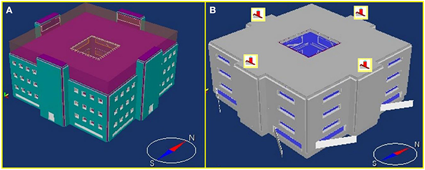
Figure 1. (A) 3-D view of the building. (B) Simplified Chimney Model.
The building is modeled by 19 zones: one Light Well, four Stacks, four zones (four different orientations) per each story, and other four to represent the Sub-floor Plenum. IDA ICE's Large Vertical Opening Model is used to simulate the four zones of each story as an open-plan area. Displacement ventilation is calculated for the Light Well and the four Stacks, where Well-Mixed Air Model is assumed for the other zones. No heating or cooling devices are installed in the Light Well and the Stacks. The typical stories are conditioned by the following systems:
• Water radiators on the external walls (under windows);
• Cooling panels on the ceiling;
• VAV (Variable Air Volume) mechanical ventilation terminals with CO2 controller;
• Large ventilation opening areas are employed as VAV actuators with PI (proportional integral) temperature controllers to provide natural cooling and ventilation at certain conditions.
Building energy modeling under IDA ICE environment is based on the following assumptions:
• The weather data file is taken from IDA ICE website1;
• The internal heat gains are set according to the values reported in Table 1;
• The thermal characteristics of the opaque building envelope are shown in Table 2. On the other hand, the windows are with PVC frame, double-glazed, argon-filled (16 mm gap). The U-value is 2.6 W/m2K. For roof windows the U-value is increased of 0.2 W/m2K (assumed for skylight). The light transmittance is 0.80, the SHGC (solar heat gain coefficient) is 0.76;
• The minimum ventilation rates during the occupied hours are set according to ANSI/ASHRAE Standard 62.1–20042, as reported in Table 3;
• the occupation schedule is set according to standard IDA ICE values (IDA-ICE, 2002);
• The general design criteria followed by thermal comfort conditions at summer and winter according to CIBSE (Chartered Institution of Building Services Engineers)3 are reported in Table 4. It is noticed that, since IDA ICE does not calculate the resultant temperature, the PPD (Predicted Percentage of Dissatisfied) index—assessed according to Fanger theory (Fanger, 1972)—is used as a measure for the thermal comfort.
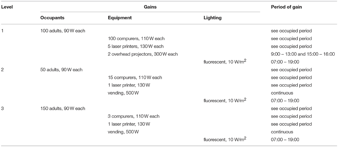
Table 1. Building internal heat gains.
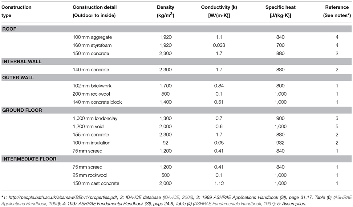
Table 2. Characterization of the building opaque envelope.
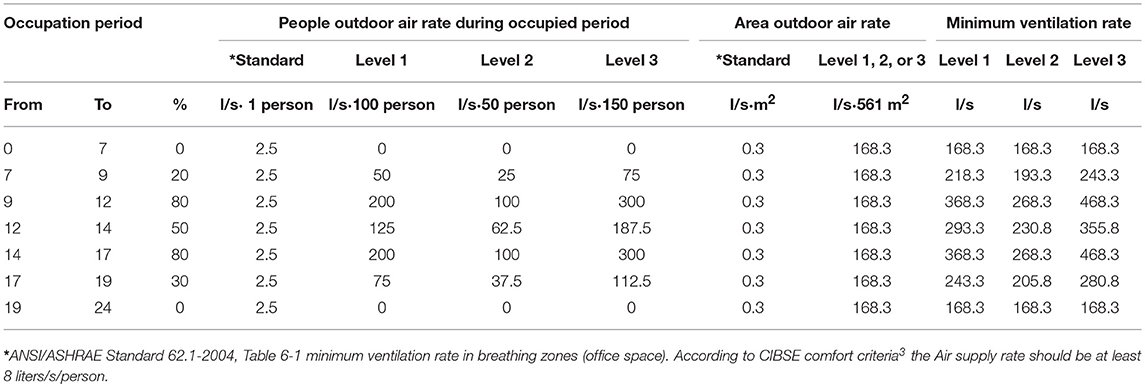
Table 3. Minimum ventilation rates.
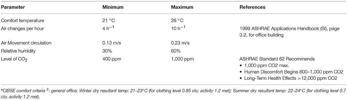
Table 4. General design criteria.
IDA ICE has two types of model to simulate the zones. The first one is the “Climate Model,” which provides more accurate results and gradient calculation. The second one is the “Energy Model,” which is faster but does not include gradients. Furthermore, IDA ICE offers three techniques to deal with the air inside the zones: Well-mixed, Displacement ventilation and Temperature gradient given by the user. In this study, the Climate Model with Displacement Ventilation is used for the Light Well and four Stacks. The Energy Model with Well-mixed technique is used for the other zones.
One way to ventilate a building that is hotter or colder on the indoor than outdoor is to use the “Stack effect.” Because of the temperature difference, the air inside the building is either more or less dense than outdoor air. If there is an opening high in the building and another low, a natural flow will be caused. If the air in the building is warmer than the outdoor, this warmer air will float out the top opening, being replaced with cooler air from outdoor. If the air inside is cooler than that outdoor, the cooler air will drain out the low opening, being replaced with warmer air from outdoor.
IDA ICE includes two types of model that can be used to simulate the Stack effect: “Chimney Model” and “Leak Model” (if it is used at the highest level with a suitable area). In the current study, the natural ventilation is modeled by using “Chimney Model” (see previous Figure 1).
As mentioned in IDA ICE documentation, “the chimney model can be inserted in ceiling or wall to describe a natural ventilation system. The model can calculate flow in both directions, i.e., if the zone pressure is low enough, air will enter the zone through the chimney. The rise of the duct and the vertical position of the input will determine the Stack effects”. By using the Chimney Model, the building is simplified by one level for the roof (see Figure 1), and the additional heights of the Stacks, above the roof building level, are modeled as unobstructed chimneys.
Chimney Model can be described by the following parameters:
• Inlet loss coefficient (Pressure drop in the inlet air terminal) set equal to 10E-6 (assumption for unobstructed chimneys) in this study;
• Outlet loss coefficient (Pressure drop in the outlet air terminal) set equal to 10E-6 (assumption for unobstructed chimneys);
• Diameter Hydraulic diameter (HD), calculated using the following equation by considering a rectangular chimney:
where a and b provide the dimensions of the Sub-floor Plenum level, represented in Figure 2, i.e., 1.5 and 6 m, respectively;
• Total rise from inlet to outlet: Height difference between inlet and outlet (governs the Stack effect), set equal to 3 m;
• Total duct length: Total hydraulic length for the duct, set equal to 3 m.
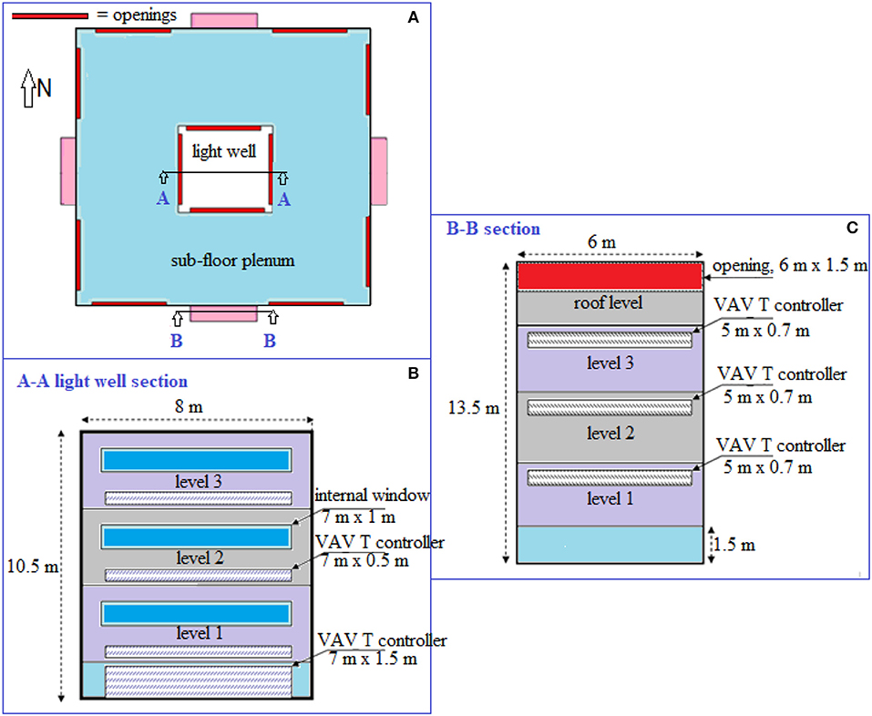
Figure 2. 2-D views of the building: (A) Sub-floor Plenum—plan. (B) Light well section A-A: low level openings from light well to each story as well as Sub-floor Plenum openings. (C) Stack section B-B: High level outlets from each story to the exhaust Stacks.
The rate at which air flows (Q) depends on several factors, i.e., the inside and outdoor air temperatures, the opening areas, the height difference between the top and bottom openings.
The 1997 ASHRAE Fundamentals Handbook (1997) gives the following relationship:
where (all the measurement units used in the ASHRAE relationship are indicated and then converted in units of the International System):
• Cd = 0.65 (for unobstructed openings);
• A = opening area, square feet;
• Ti = indoor temp (Rankine), 533.07 R = 23 °C = 296.15 K;
• To = outdoor temp (Rankine), minimum temperature in the Stack, 516.87 R = 14°C = 287.15 K;
• Hn = height of “neutral pressure point” (for simple systems, assume 1/2 way between top and bottom openings);
• Hb = height of bottom opening;
• Hn-Hb = 42.65 ft = 13 m;
• g = gravity = 32 ft/s2 = 9.81 m/s2.
The assessed Q value (15.727 l/s) can be considered as a maximum air flow rate through the Stack to check the simulation results.
According to ASHRAE guidelines (ASHRAE Fundamentals Handbook, 1997; ASHRAE Applications Handbook, 1999), the opening areas can be assumed in the range 1–2.5% of the floor area being served. This section describes the sizing process for the opening areas between: outdoor and Sub-floor Plenum; Sub-floor Plenum and Light Well; Light Well and floor; floor and Stacks. All these unobstructed large vertical opening areas are considered as VAV actuators which operate according to the adopted control strategy. The main employed parameters are reported below:
• Maximum free areas according to the mentioned guidelines = 0.025 x Building served areas = 42 m2;
• Building served areas = (Floor area—Light well area) x No. floors = ((25 × 25)–(8 × 8)) x 3 = 1683 m2.
Thus, the opening areas are sized as follows:
– Sizing of the opening areas between outdoor and Sub-floor Plenum:
• number of the opening areas (fresh air inlets) = 8 (assuming 2 fresh air inlets at each facade);
• area = 42 / 8 = 5.25 m2;
• width = 7 m (assumption);
• height = 5.25 m2/ 7 m = 0.75 m.
– Sizing of the opening areas between Sub-floor Plenum and Light Well:
• number of the opening areas = 4 (assumption for a square light well);
• area = 42 / 4 = 10.5 m2;
• width = 7 m (assumption);
• height = 10.5 m2/ 7 m = 1.5 m.
– Sizing of the opening areas between Light-Well and 3-story:
• number of the opening areas = 4 (per each story);
• total number of the opening areas = 4 * 3 story = 12;
• area = 42 / 12 = 3.5 m2;
• width = 7 m (assumption);
• height = 3.5 m2/ 7 m = 0.5 m.
– Sizing of the opening areas between Floor and Stack:
• number of the opening areas = 4 (per each story);
• total number of the opening areas = 4 * 3 story = 12;
• area = 42 / 12 = 3.5 m2;
• width = 5 m (assumption);
• height = 3.5 m2/ 5 m = 0.7 m.
The current study investigates four different ventilation control strategies: traditional mechanical ventilation control strategy (Mechanical), hybrid-ventilation control strategy 1 (Hybrid 1), hybrid-ventilation control strategy 2 (Hybrid 2) and hybrid- ventilation control strategy 3 (Hybrid 3).
The same heating and mechanical ventilation systems are used for all the suggested control strategies. Four water radiators are installed in each story: two under the east windows and other two under the west windows. The sizes of these water radiators are selected to be large to cover any increase in the space heating demand that can occur due to applying the hybrid-ventilation control strategies. The main objective of the water radiators is to maintain the three stories at 21 (± 1) °C during the occupied hours and 19 (± 1) °C at night. Figure 3A presents the night set-back of the water radiators. Variable air volume (VAV) system is used to maintain the occupied zones below the maximum CO2 level (1,000 ppm). The AHU (air handling unit) includes variable speed fan, heating coil, cooling coil and heat recovery. The supply air temperature is a function of ambient (outdoor) temperature, as shown in Figure 3B, trying to avoid any need for cooling in the AHU.
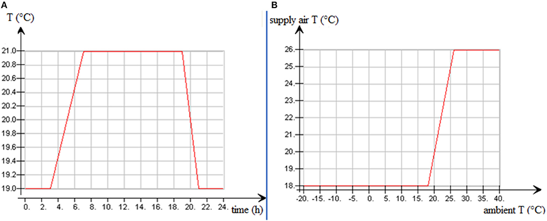
Figure 3. (A) Night set-back of the water radiators. (B) Supply air temperature as a function of ambient (outdoor) air temperature.
In addition to the water radiators and VAV mechanical ventilation system, two identical cooling panels with PI (Proportional Integral) controllers are installed in each story. The sizes of cooling panels are determined to cover the peak load at the warmest day (May 18). The selection process of the cooling panels is performed according to the following design criteria:
• Indoor air temperature set point = 26 (+ 1)°C;
• Temperature difference between indoor air and cooling panel at peak load (dTaw) = 11°C;
• Water temperature rise through the cooling panel at peak load (dTw) = 4°C;
• Inlet water temperature for cooling panel (Twi) = 14°C.
Thus, at the peak load (it occurs only 2 days in the whole year):
• Cooling panel temperature = Twi + dTw/2 = 14 +4/2 = 16 °C;
• Indoor air temperature = Cooling panel temperature + dTaw = 16 + 11 = 27 °C.
• Finally, the panels have the following resulting sizes:
• First level: Two cooling panel of 9 kW;
• Second level: Two cooling panels of 7 kW;
• Third level: Two cooling panels of 5 kW.
The main idea is to keep the Light Well at the lowest possible acceptable-temperature (e.g., 23°C) by natural ventilation, then using the air of the Light Well to cool and/or vent the occupied zones as much as possible. This can be applied by using the opening areas between the Light Well and the typical story as VAV-cooling actuators. To give a possibility for the natural air to flow through the story, the opening areas between the typical story and the four Stacks are also employed as VAV actuators with the same control signal of the Light Well opening areas (see Figure 4). As a concept, the four opening areas between the Light Well and the Sub-floor Plenum and the other eight between the Sub-floor Plenum and the outdoors are all used as VAV actuators with a certain set points as described below. The used control method is always the PI.
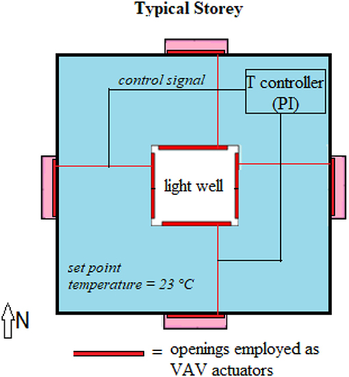
Figure 4. Hybrid 1: Typical story using the light well as a cooling source and the stacks as vents.
Concerning the control of the opening areas between the occupied zones (typical story) and the Light Well, the target is trying to keep the occupied zones at 23 ± 1°C or to provide it with maximum natural ventilation at higher temperature. This means that, for maximum ventilation, the opening areas are fully open if the occupied zone temperature is higher than 24°C and the outdoor temperature is < 26°C. As regards the actuators, four large opening areas (7 × 0.5 m between the story and the Light Well) and other four large opening areas (5 m x 0.7 m between the story and the four Stacks) all work as VAV actuators only if the Light Well temperature is less than 26°C. If the Light Well temperature is higher than 26°C, the control system closes all opening areas between the Light Well and the occupied zones and those between the occupied zones and the four Stacks. In this case, the AHU provides each story by a minimum amount of fresh air to maintain the CO2 level < 1,000 ppm using the VAV mechanical ventilation system. On the other hand, if the temperature of the occupied zone is <22°C (near to the water radiator set point 21°C), the PI controller shuts down the opening areas. In this case, the AHU also provides the story by a minimum amount of fresh air to maintain the CO2 level < 1,000 ppm using the VAV mechanical ventilation system.
Concerning the control of the opening areas between the Light Well and the Sub-floor Plenum, the target is trying to keep the Light Well at 23 ± 1°C or to provide it with maximum natural ventilation at higher temperature. This means, for maximum ventilation, that opening areas are fully open if the Light Well temperature is higher than 24°C and the outdoor temperature is < 26°C. As regards the actuators, four large opening areas (7 × 1.5 m between the Light Well and the Sub-floor Plenum 5) work as VAV actuators, while the Sub-floor Plenum temperature is < 23°C. If the Sub-floor Plenum temperature is higher than 23°C, all the opening areas between the Light Well and the Sub-floor Plenum are fully open to provide the Light Well with maximum natural ventilation.
Concerning the control of the opening areas between the Sub-floor Plenum and outdoor, the target is trying to keep the Sub-floor Plenum at 23 ± 1°C. This value is selected to prevent the heat to transfer from the first occupied level to the Sub-floor Plenum trying to avoid any increase in the space heating energy. However, this will feature as a bad selection (i.e., control strategy). That's why Hybrid 2 and Hybrid 3 adopt lower set point temperatures for the Sub-floor Plenum to permit the heat to transfer from the first occupied level to the sub-floor during the working hours. As regards the actuators, eight large opening areas (7 × 0.75 m between the Sub-floor Plenum and outdoor) work as VAV actuators only if the outdoor air temperature is in between 12 and 24.5°C. If the outdoor temperature is higher than 24.5°C, all the opening areas between outdoor and the Sub-floor Plenum are fully open to provide maximum natural ventilation.
The hybrid ventilation control strategy 1 (Hybrid 1) adopts 23°C as set point temperature for the Sub-floor Plenum. As a result (see section Results), the controlled opening areas between the outdoor and the Sub-floor Plenum are closed for most year hours. The current control strategy (Hybrid 2) tries to keep the Sub-floor Plenum at lower temperature (19°C) during the working hour (7:00–19:00) when there is a high load in the first occupied level (first floor). This avoids the increase of space heating energy. The main difference between Hybrid 1 and Hybrid 2 is the number of the controlled opening areas, since, for natural cooling and ventilation, 18 opening areas are used by Hybrid 2 as VAV actuators with temperature controllers:
• Two opening areas between the outdoor and the Sub-floor Plenum (see Figure 5A) are controlled as VAV cooling actuators using PI temperature controller trying to maintain the Sub-floor Plenum at 19 (±1)°C during the working hours only if the ambient temperature is higher than 5°C. Otherwise, all opening areas are closed. If the outdoor temperature is higher than 19°C during the working hours, all opening ventilation areas are fully open to provide the building with maximum natural ventilation. As much the ambient temperature raises the natural air velocity increases:
• Four opening areas between the Sub-floor Plenum and the Light Well (see Figure 5A) are controlled as VAV cooling actuators using PI temperature controller trying to maintain the Light Well at 22 (±1)°C while the Sub-floor Plenum temperature is < 23°C. If the Light Well temperature is less than 21°C, all the controlled opening areas are closed. This reduces the heat loss from the occupied zones to the Light Well in winter;
• Three opening areas between the Light Well and each story —for a total of nine —(Figure 5B) are controlled as VAV cooling actuators using PI temperature controllers trying to maintain the occupied zones at 22.5 (±1)°C while the Light Well temperature is <22.5°C. Otherwise, if the occupied zone and Light Well temperature is higher than 23.5°C, the opening areas are fully open to provide the occupied zone with maximum natural ventilation increasing the velocity of the natural air inside the zone. If the Light Well temperature is higher than 26°C, the control system closes all opening areas between the Light Well and the occupied zones. In this case, the AHU provides each zone with a minimum amount of fresh air to maintain the CO2 level < 1,000 ppm using the VAV mechanical ventilation system. On the other hand, if the temperature of the story is <21.5°C (near to water radiator set point), the PI controller shuts down the opening areas. In this case, the AHU provides the story with a minimum amount of fresh air to maintain the CO2 level <1,000 ppm using the VAV mechanical ventilation;
• One opening area between each story and the east Stack—for a total of three–(Figure 5B) is controlled as VAV cooling actuators using PI temperature controller trying to maintain the stories at 22.5 (±1)°C. This opening area takes the same control signal of the three opening areas between the Light Well and each story.
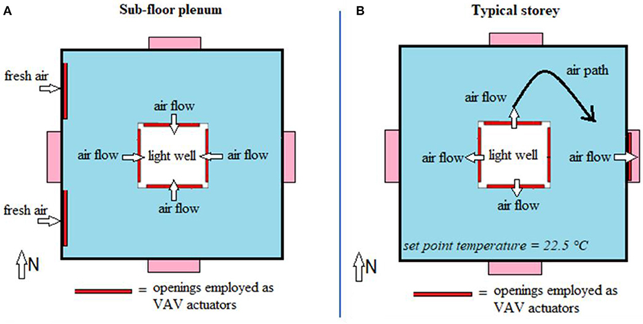
Figure 5. Hybrid 2. (A) Sub-floor Plenum—plan. (B) Typical story—plan.
Hybrid 3 is a modification for Hybrid 2 with three main differences:
• Hybrid 3 uses temperature-CO2 controllers for the VAV mechanical supply air terminals to keep the occupied zones at temperature < 26°C and CO2 level < 1,000 ppm using the mechanical ventilation system, while Hybrid 2 uses only CO2 controllers for these terminals.
• The natural ventilation process is permissible only if the outdoor air temperature is between 5°C and 24°C. Otherwise, the AHU provides the 3-story by a minimum amount of fresh air to maintain the CO2 level < 1,000 ppm using the VAV mechanical ventilation system. On the other hand, like Hybrid 1 and Hybrid 2, the AHU also runs at any moment if the natural ventilation is not enough to keep the occupied zones at CO2 level < 100 ppm.
• Hybrid 3 uses the same eighteen opening areas that are employed in Hybrid 2 as VAV cooling actuators (see section Hybrid Ventilation Control Strategy 2 (Hybrid 2)). The difference is that Hybrid 3 uses variable temperature set point temperatures (the set point is a function of the outdoor temperature) for the occupied zones, Light Well, Sub-floor Plenum, as shown in the following Figure 6. It is noticed that these set points are used for the controllers of the opening areas (not for mechanical cooling or heating system).
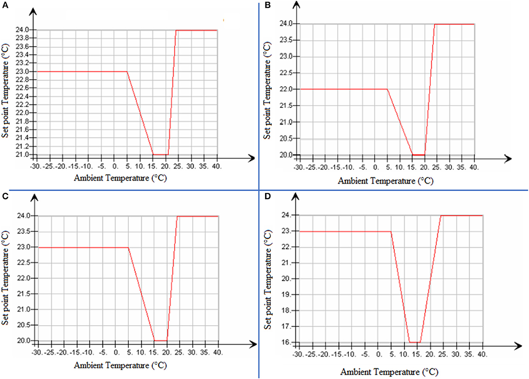
Figure 6. Hybrid 3, Set point temperature for: the occupied zones using the opening areas between the ones and the Light Well as VAV cooling actuator. (A) The light well using the areas between the light well and the Sub-floor Plenum as actuator. (B) For the Sub-floor Plenum using the areas between the Sub-floor Plenum and the outdoor as actuator during unoccupied (C) and occupied (D) hours.
Figure 6A presents the set point temperature of the occupied zones. This Figure indicates that, if the ambient temperature is < 5°C, there is no natural ventilation for the occupied zone except if the zone temperature tends to be higher than 23°C. This reduces the probability of increase the space heating energy due to the natural ventilation in winter. Figure 6A shows that, if the ambient temperature is between 15and 20°C, the occupied zone set point temperature is 21°C. This provides the zone with much natural cooling and ventilation during the working hours and much night ventilation to remove the heat from the building. If the ambient temperature is higher than 21°C, there is no way (by using natural cooling) to reduce indoor temperature more than this limit. Putting the set point temperature equal to the ambient temperature provides the zones with maximum natural ventilation to reduce the fan energy as well as to keep the zone temperature < 24°C as possible. If the ambient and the zone temperature are higher than 24°C, the AHU runs at higher speed to provide the zone with much air for cooling and ventilation at the same time (in this case the Light Well temperature is higher than 26°C and the opening areas between the Light Well and the zones are closed).
By using the variable set points temperatures shown in Figure 6, Hybrid 3 provides the zones with a suitable natural air flow during the occupied hours based on the outdoor temperature and makes night ventilation only in the summer season. In particular, putting the set point temperature of the Sub-floor Plenum at 23°C when the ambient temperature is < 5°C, see Figure 6C, keeps the opening areas between the outdoor and Sub-floor Plenum closed at the unoccupied hours in the cold winter. This provides better thermal comfort in the different occupied zones across the whole year with less increase in space heating demand. In this regard, during the occupied hours, when the ambient temperature is 10°C or lower, putting the set point temperature of the Sub-floor Plenum at 18 °C, and not at 16°C for example (see Figure 6D), keeps the building fabric at higher temperature, reducing the increase of heating demand that likely occurs due to natural ventilation.
Hybrid 1 does not work as what was expected. The sub-floor opening areas are maintained closed except when the outdoor air temperature exceeds 24.5°C. The natural air flow enters from the east Stack and exits from the north Stack during all the year hours. On the other hand, the natural air flow enters from the south Stack and exits from the west during the winter. However, the natural air flow enters from the west Stack and exists from the south Stack during the summer. The natural air flow exits from the north Stack only in the warmest days when the temperature is higher than 25°C. For demonstration purposes, in the Appendix, Hybrid 1 is characterized as concerns opening areas control signals and temperatures in the three levels, Light Well, and Sub-floor Plenum (see Figure A1), as well as mean air temperatures inside the west, south, and north Stack vs. the year hours (see Figure A2). Since the natural air flow enters from the west, south, and north Stacks, such temperatures are important to be observed. During the occupied hours the temperature is higher than 14°C. However, the temperature decreases at night. Entering the natural air at quite low temperature (14°C) increases the space heating energy. Furthermore, it could be unacceptable for the thermal comfort particularly at the first story level. The results of this case are important to recognize the behavior of the Stack effect at the four directions (four orientations) if there is no probability to enter the natural air from the Sub-floor Plenum.
Based on these unsatisfying results of Hybrid 1, the other two hybrid ventilation control strategies (Hybrid 2 and Hybrid 3) are proposed and investigated to enter the air from the Sub-floor Plenum and exit the air from east Stack. In particular, during the working hours, the natural airflow enters through the controlled opening areas between the outdoor and the Sub-floor Plenum, then transfers to the Light Well reducing its temperature.
According to the temperature of each story, the natural air spreads inside the story then exits from the east Stack. The natural airflow passes through the building (enters through the Sub-floor Plenum and exists from the east Stack) and, as a result, the three stories are kept within a range of acceptable temperatures [according to ASHRAE 1999 (ASHRAE Applications Handbook, 1999)] for most of the year hours.
In particular, the following lines compare the results of the four mentioned control strategies: Mechanical ventilation, Hybrid 1, Hybrid 2 Hybrid 3. The aim is to assess the best solution by means of multi-criteria decision making according to the following performance criteria:
• Annual space heating energy (Figure 7A);
• Annual cooling energy (Figure 7B);
• Annual fan energy assuming constant efficiency (Figure 7C);
• Annual AHU heating energy neglecting the effect of the heat recovery (Figure 7D);
• Annual duration curve of the space heating power (Figure 8);
• PPD index (see Figure 9 as concerns June and July); as concerns the analysis of thermal comfort, Figure A3 of the Appendix shows the annual trends of average indoor air temperature in the 3 stories for the proposed hybrid ventilation strategies;
• Indoor air quality represented by CO2 level (Figure 10) and natural air passes through the building vs. the year hours (Figure 11).
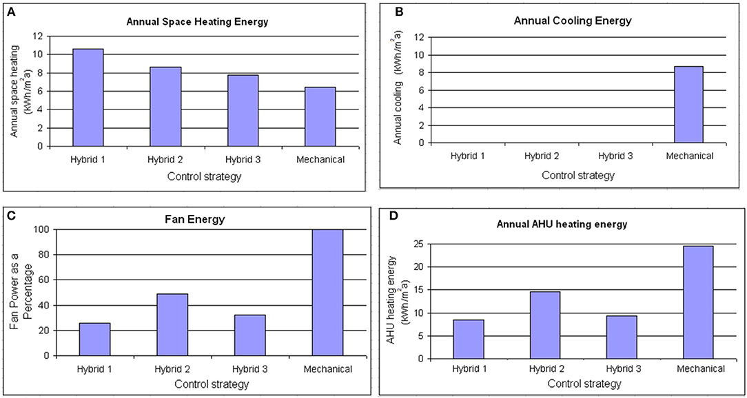
Figure 7. Comparison of the investigated ventilation strategies: (A) Annual space heating energy. (B) Annual cooling energy. (C) Annual AHU fan energy assuming constant fan efficiency. (D) Annual AHU heating energy neglecting the heat recovery.
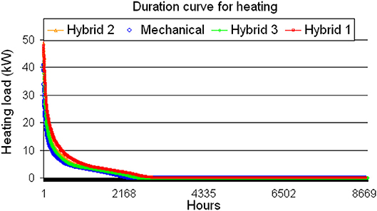
Figure 8. Duration curve of the space heating power.
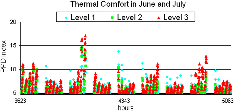
Figure 9. Average PPD at different orientations during June and July using Hybrid 3 (assuming2 clothing level = 0.7 clo; activity = 1.2 met; air velocity = 1.2 m/s).
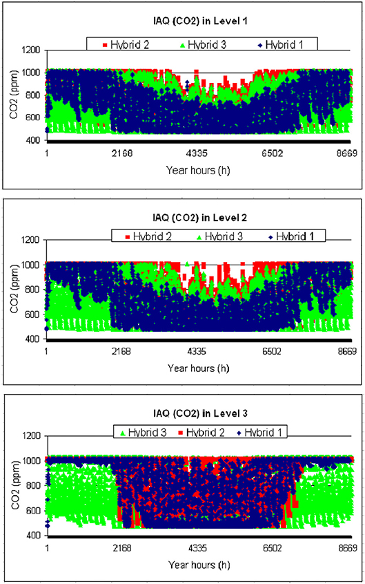
Figure 10. CO2 as a measure for the indoor air quality in the building levels for the proposed hybrid ventilation strategies.
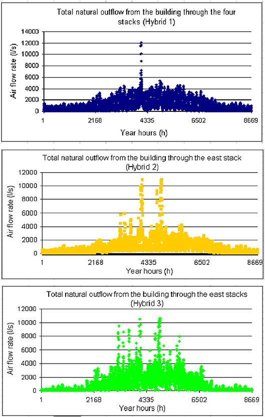
Figure 11. Total outflow from the building through the east Stack for the proposed hybrid ventilation strategies.
The three suggested hybrid ventilation control strategies (Hybrid 1, 2, and 3) can save 100% of the cooling energy maintaining the occupied zones at different levels of suitable comfort and healthy conditions. Moreover, a significant percentage of the fan and AHU heating energy can be saved. However, the space heating energy increases because a set of reasons:
• Entering the natural air at low temperature (14°C) from the Stack itself (this occurs for Hybrid 1);
• Providing natural ventilation in the weekend and unoccupied hours in winter;
• The small overlapping between the natural cooling set point (22.5 ± 1°C) and water radiator set point (21 ± 1°C) (this occurs for Hybrid 2);
• Using oversized heating system (this occurs for Hybrid 1);
• Providing natural ventilation for the Sub-floor Plenum and Light Well at early morning (at 7:00) when the ambient temperature is low (this occurs for Hybrid 2);
• Reducing the temperature of the building construction by night ventilation (this occurs for Hybrid 1 and 3).
On the other hand, the night ventilation, in summer, is important to achieve high thermal comfort inside the occupied zones. This idea is adopted by using the hybrid ventilation control strategy 3 (Hybrid 3). Concerning Hybrid 1, the Sub-floor Plenum is maintained close most of the year hours because of the high set point temperature (23°C), which is selected for it to reduce the heat loss. The night ventilation is not used by Hybrid 2. This causes much of overheating hours in the south and east zones. In order to avoid these problems, Hybrid 3 uses variable temperature set points, based on the ambient temperature, for the occupied zone, Light Well, and Sub-floor Plenum. This improves the energy, thermal comfort and IAQ results. Therefore, Hybrid 3 represents the best solution to be implemented, since it ensures the best trade-off among the considered energy, comfort and IAQ performance criteria.
The study implemented IDA ICE to perform the multi-criteria assessment of the best hybrid ventilation system for an open plan office building located in Glasgow (Scotland) with Stack assisted cross ventilation. Three different hybrid ventilation control strategies (Hybrid 1, Hybrid 2 and Hybrid 3) are suggested and compared vs. a traditional mechanical ventilation system. Different criteria related to comfort, IAQ and energy needs are considered to assess the best strategy. The results indicate that by adopting those three control strategies there is no need for mechanical cooling. The first and second control strategies can save about 75% and 50% of AHU fan energy, but the space heating increases by about 4.2 kWh/m2a and 2.2 kWh/m2a, respectively. Hybrid 1 and Hybrid 2 achieve most of the thermal comfort requirements. However, the first supplies quite low natural air temperature to the occupied zone (14°C) and the second cannot maintain the PPD (predicted percentage of dissatisfied) level < 25% through all the year hours at the south and the east zones. Hybrid 3 is proposed as a matured hybrid ventilation control strategy which saves 68% of the fan energy with less increase in the space heating energy (1.3 kWh/m2a) achieving a good thermal and healthy conditions at the three stories. Thus, it represents the best solution, which ensures the best trade-off among the examined performance criteria. Furthermore, the three hybrid ventilation systems can also save much of the AHU heating power, if they are compared with a mechanical ventilation system without heat recovery (or with low efficiency heat recovery). For future works, optimization algorithm can be implemented to achieve a further enhancement of the chosen hybrid ventilation system.
All datasets generated for this study are included in the manuscript and/or the Supplementary Files.
MH conceived the idea, performed simulations and wrote the first draft of this manuscript. GM revised the manuscript prior to publication.
The authors declare that the research was conducted in the absence of any commercial or financial relationships that could be construed as a potential conflict of interest.
The Supplementary Material for this article can be found online at: https://www.frontiersin.org/articles/10.3389/fbuil.2019.00097/full#supplementary-material
1. ^http://www.equaonline.com/iceuser/
2. ^ANSI/ASHRAE Standard 62.1-2004
Achermann, M., and Zweifel, G. (2003). RADTEST Radiant Cooling Heating Test Cases. Task 22: Building Energy Analysis Tools. International Energy Agency, Solar Heating Cooling Programme.
ASHRAE Applications Handbook (1999). Chapter 36-Testing. Adjusting and Balancing. American Society of Heating. Refrigeration and Air-Conditioning Engineers. Atlanta, GA.
ASHRAE Fundamentals Handbook (1997). Fundamentals. American Society of Heating. Refrigeration and Air-conditioning Engineers. Atlanta, GA.
Bring, A., Sahlin, P., and Vuolle, M. (1999). Models for Building Indoor Climate and Energy Simulation, Royal Institute of Technology (Stockholm: TBEA Tools).
Calay, R. K., and Wang, W. C. (2013). A hybrid energy efficient building ventilation system. Appl. Therm. Eng. 57, 7–13. doi: 10.1016/j.applthermaleng.2013.03.042
Chen, J., Augenbroe, G., and Song, X. (2018). Evaluating the potential of hybrid ventilation for small to medium sized office buildings with different intelligent controls and uncertainties in US climates. Energy Build. 158, 1648–1661. doi: 10.1016/j.enbuild.2017.12.004
Chen, J., Brager, G. S., Augenbroe, G., and Song, X. (2019). Impact of outdoor air quality on the natural ventilation usage of commercial buildings in the US. Appl. Energy 235, 673–684. doi: 10.1016/j.apenergy.2018.11.020
Chen, X., and Yang, H. (2017). Sensitivity analysis and optimization of a typical passively designed residential building with hybrid ventilation in hot and humid climates. Energy Proc. 142, 1781–1786. doi: 10.1016/j.egypro.2017.12.563
Crawley, D. B., Hand, J. W., Kummert, M., and Griffith, B. T. (2008). Contrasting the capabilities of building energy performance simulation programs. Build. Environ. 43, 661–673. doi: 10.1016/j.buildenv.2006.10.027
Emmerich, S. J. (2006). Simulated performance of natural and hybrid ventilation systems in an office building. HVAC & R Res. 12, 975–1004. doi: 10.1080/10789669.2006.10391447
Emmerich, S. J., Polidoro, B., and Axley, J. W. (2011). Impact of adaptive thermal comfort on climatic suitability of natural ventilation in office buildings. Energy Build. 43, 2101–2107. doi: 10.1016/j.enbuild.2011.04.016
Ezzeldin, S., and Rees, S. J. (2013). The potential for office buildings with mixed-mode ventilation and low energy cooling systems in arid climates. Energy Build. 65, 368–381. doi: 10.1016/j.enbuild.2013.06.004
Fanger, P. O. (1972). Thermal Comfort, Analysis and Application in Environmental Engineering. New York, NY: McGrew-Hill.
Fu, X., and Wu, D. (2015). Comparison of the efficiency of building hybrid ventilation systems with different thermal comfort models. Energy Proc. 78, 2820–2825. doi: 10.1016/j.egypro.2015.11.640
Hamdy, M., Hasan, A., and Siren, K. (2009). “Combination of optimisation algorithms for a multi-objective building design problem,” in IBPSA: 11th International Building Performance Simulation Association Conference (Glasgow).
Hurnik, M., Specjal, A., and Popiolek, Z. (2017). On-site diagnosis of hybrid ventilation system in a renovated single-family house. Energy Build. 149, 123–132. doi: 10.1016/j.enbuild.2017.05.034
IDA-ICE (2002). IDA Indoor Climate and Energy. EQUA, IDA Indoor Climate and Energy 3.0 User's Guide, EQUA Simulation. Stockholm. Available online at: https://www.equa.se/deliv/ice3eng.pdf (accessed July 26, 2019)
Ji, Y., Lomas, K. J., and Cook, M. J. (2009). Hybrid ventilation for low energy building design in south China. Build Environ. 44, 2245–2255. doi: 10.1016/j.buildenv.2009.02.015
Lim, Y. H., Yun, H. W., and Song, D. (2015). Indoor environment control and energy saving performance of a hybrid ventilation system for a multi-residential building. Energy Proc. 78, 2863–2868. doi: 10.1016/j.egypro.2015.11.653
Mahdavi, A., and Pröglhöf, C. (2008). A model-based approach to natural ventilation. Build. Environ. 43, 620–627. doi: 10.1016/j.buildenv.2006.06.023
Menassa, C. C., Taylor, N., and Nelson, J. (2013a). Optimizing hybrid ventilation in public spaces of complex buildings–a case study of the Wisconsin Institutes for Discovery. Build. Environ. 61, 57–68. doi: 10.1016/j.buildenv.2012.12.009
Menassa, C. C., Taylor, N., and Nelson, J. (2013b). A framework for automated control and commissioning of hybrid ventilation systems in complex buildings. Automat. Construct. 30, 94–103. doi: 10.1016/j.autcon.2012.11.022
Solgi, E., Hamedani, Z., Fernando, R., Skates, H., and Orji, N. E. (2018). A literature review of night ventilation strategies in buildings. Energy Build. 173, 337–352. doi: 10.1016/j.enbuild.2018.05.052
Spindler, H. C., and Norford, L. K. (2009). Naturally ventilated and mixed-mode buildings—Part II: Optimal control. Build. Environ. 44, 750–761. doi: 10.1016/j.buildenv.2008.05.018
Tovar, R., Linden, P. F., and Thomas, L. P. (2007). Hybrid ventilation in two interconnected rooms with a buoyancy source. Solar Energy 81, 683–691. doi: 10.1016/j.solener.2006.08.009
Tuohy, P. G., Rijal, H. B., Humphreys, M. A., Nicol, J. F., Samuel, A., and Clarke, J. A. (2007). “Comfort driven adaptive window opening behaviour and the influence of building design,” in Proceedings of Building Simulation 2007, 10th IBPSA Conference. IBPSA. Available online at: http://www.ibpsa.org/proceedings/BS2007/p544_final.pdf (accessed May 15, 2019)
Wang, B., and Malkawi, A. (2019). Design-based natural ventilation evaluation in early stage for high performance buildings. Sustain Cities Soc. 45, 25–37. doi: 10.1016/j.scs.2018.11.024
Yang, D., and Li, P. (2015). Dimensionless design approach, applicability and energy performance of stack-based hybrid ventilation for multi-story buildings. Energy 93, 128–140. doi: 10.1016/j.energy.2015.08.115
Yang, L., Liu, X., Qian, F., and Du, S. (2019). Ventilation effect on different position of classrooms in “line” type teaching building. J. Clean. Product. 209, 886–902. doi: 10.1016/j.jclepro.2018.10.228
Yao, R., Li, B., Steemers, K., and Short, A. (2009). Assessing the natural ventilation cooling potential of office buildings in different climate zones in China. Renew. Energy, 34, 2697–2705. doi: 10.1016/j.renene.2009.05.015
Yoshino, H., Liu, J., Lee, J., and Wada, J. (2003). Performance analysis on hybrid ventilation system for residential buildings using a test house. Indoor Air 13, 28–34. doi: 10.1034/j.1600-0668.13.s.6.4.x
Yuan, S., Vallianos, C., Athienitis, A., and Rao, J. (2018). A study of hybrid ventilation in an institutional building for predictive control. Build. Environ. 128, 1–11. doi: 10.1016/j.buildenv.2017.11.008
Zhai, Z. J., Johnson, M. H., and Krarti, M. (2011). Assessment of natural and hybrid ventilation models in whole-building energy simulations. Energy Build. 43, 2251–2261. doi: 10.1016/j.enbuild.2011.06.026
Keywords: hybrid ventilation, office buildings, multi-criteria decision making, air handling units, building energy performance, indoor air quality
Citation: Hamdy M and Mauro GM (2019) Optimizing Hybrid Ventilation Control Strategies Toward Zero-Cooling Energy Building. Front. Built Environ. 5:97. doi: 10.3389/fbuil.2019.00097
Received: 15 February 2019; Accepted: 18 July 2019;
Published: 08 August 2019.
Edited by:
Amy Ahim Kim, University of Washington, United StatesReviewed by:
Sanja Stevanovic, Serbian Academy of Sciences and Arts, SerbiaCopyright © 2019 Hamdy and Mauro. This is an open-access article distributed under the terms of the Creative Commons Attribution License (CC BY). The use, distribution or reproduction in other forums is permitted, provided the original author(s) and the copyright owner(s) are credited and that the original publication in this journal is cited, in accordance with accepted academic practice. No use, distribution or reproduction is permitted which does not comply with these terms.
*Correspondence: Mohamed Hamdy, bW9oYW1lZC5oYW1keUBudG51Lm5v
Disclaimer: All claims expressed in this article are solely those of the authors and do not necessarily represent those of their affiliated organizations, or those of the publisher, the editors and the reviewers. Any product that may be evaluated in this article or claim that may be made by its manufacturer is not guaranteed or endorsed by the publisher.
Research integrity at Frontiers
Learn more about the work of our research integrity team to safeguard the quality of each article we publish.