- 1Division of Mechanics, Department of Civil Engineering, Engineering Faculty, Nigde Ömer Halisdemir University, Nigde, Turkey
- 2Division of Mechanics, Department of Civil Engineering, Engineering Faculty, Nigde Ömer Halisdemir University, Nigde, Turkey
- 3Department of Civil Engineering, Engineering Faculty, Hacettepe University, Ankara, Turkey
Viscous dampers (VDs) are effective and widely used passive devices for the protection of civil structures, provided that appropriate design is carried out. For this purpose, optimal design and optimum distribution of VDs method are presented for a shear building under the critical excitation by using random vibration theory in the frequency domain. In the optimization, by using Differential Evolution (DE) algorithm and the top floor displacement are evaluated as objective functions taking into consideration upper and lower limits of VDs damping coefficients, so that optimal damper placement and properties of the shear building can be determined. In this design, the VDs-shear building system is tested under the three different ground motions being compared to some methods in the literature and uniformly distributed VDs placed at each story. It is shown that the results of the study are both compatible and very successful in reducing the response of the structure under the different ground motions.
Introduction
In traditionally designed building structures, reduction of enormous vibration energy is inadequate because of their very limited energy absorption capacity. Therefore, usage of passive, semi-active or active energy dissipation systems has more and more come into prominence in civil engineering structures. Even if limited damping about 40% capacity of damping quantity is applied, owing to the physical and manufactural difficulties, optimally designed and placed viscous dampers (VDs) significantly decrease the response of building structures. Two endpoints of a VD are attached to two subsequent floors. Because of the relative velocity between these two floors, VDs produce a damping force which is proportional to damping coefficient and relative velocities.
The optimal design concept of VD has been widely studied in the literature (Constantinou and Tadjbakhsh, 1983; Hahn and Sathiavageeswara, 1992; Zhang and Soong, 1992; Cao and Mlejnek, 1995; Shukla and Datta, 1999). In a planar building frame, an optimum algorithm was developed by Tsuji and Nakamura (1996) including both story stiffnesses and damping coefficients. Active control-based design of VD was developed by some researchers (Gurgoze and Muller, 1992; Hwang et al., 1995; Gluck et al., 1996; Agrawal and Yang, 1999, 2000; Loh et al., 2000; Yang et al., 2002; Lavan et al., 2008). Trombetti and Silvestri (2006) analytically examined the effect of manufactured viscous dampers which are added to shear-type structures for type of Rayleigh damping systems. Takewaki (1997a) presented both a proportional and a non-proportional redesign passive damper method including viscous and hysteretic dampers. In his other study (Takewaki, 1997b), taking into consideration the undamped fundamental frequency of structure model, the sum of amplitudes of transfer functions was minimized in order to find damping coefficients of added dampers. In another study proposed by Takewaki (1999a), optimal damper placement in a three-dimensional (3D) shear structure model was executed with the method called “Steepest Direction Search Algorithm.” This method was used for optimum stiffness and viscous damper distribution (Takewaki, 1999b). Therefore, the effectiveness of the gradient-based design of VDs was revealed by Takewaki (2009). A simple and powerful VDs optimization and distribution method on the basis of total damper cost function minimization was developed by Aydin (2013). During the optimization of VDs design, direct search optimization techniques do not need derivatives and Hessians, so that some metaheuristic algorithms can be also used (Bishop and Striz, 2004; Dargush and Sant, 2005; Sonmez et al., 2013). Cetin et al. (2017) studied the optimal placement of VDs in TMD-shear building structure system. Bogdanovic and Rakicevic (2019) presented an optimal damper placement procedure in a 3D 5-story steel frame structure by using combined fitness function. Aydin et al. (2019) investigated optimum design and efficiency of VDs for earthquake-effected structures taking into consideration different mode behaviors. De Domenico et al. (2019) successfully summarized the organization of design strategies of fluid VDs in their study. Akehashi and Takewaki (2019) developed a new VD optimization and distribution method in an elastic-perfectly plastic model for multi-degree of freedom systems by using a critical double impulse pushover (DIP) method which is proposed to determine the input velocity level of critical double impulse. The form of non-linear viscous fluid dampers (FVDs) is examined by De Domenico and Ricciardi (2019) for the protection of earthquake-effected structures. In their study, a novel equal-energy on non-Gaussian stochastic method combined with the optimal design operation is applied in order to deal with the non-linearity of fluid viscous dampers (FVDs).
In practice, linear VDs, which develop forces that are a linear function of (i.e., proportional to) the relative velocity between their ends can be manufactured and applied to structure in practice. However, in order to attain flexibility in design, non-linear type VDs widely manufactured and used in many application (Hart and Wong, 2000). Non-linear VDs design is mostly considered in the time domain. However, they may be optimized in the frequency domain if specific models are developed. Fujita et al. (2014) suggested a technique related to the optimal design allocation of non-linear viscous dampers in the frequency domain. They applied the Output Frequency Response Function (OFRF) concept in their study. Adachi et al. (2013) suggested a non-linear VDs design for multi-degree freedom building frame structures. This method consists of two steps. The first step is that the sensitivity analysis in the time domain is executed on non-linear VDs model. The second step is the modification of auxiliary forces which is based on sensitivity analysis. In order to calculated loads on the frame, static condensation method and the transformation of energy equality procedure are defined to optimum operation. Lang et al. (2013) proposed a novel technique for VDs and their placement in multi-degree of freedom shear frame systems. The general idea of this study is based on the Frequency Response Function (OFRF) concept. Silvestri et al. (2010) proposed a practical and highly efficient method for both the design of linear and non-linear viscous dampers with respect to total dampers and dampers for placed specific floors. Lopez Garcia and Soong (2002) proposed a practical design approach of optimal linear type viscous dampers by using designed simplified sequential search algorithm (SSSA) which has a similar effect with some sophisticated methods. However, they aimed at more extensive examination in order to attain better performance. They are also showed that, design of linear type viscous dampers is sensitive to ground motion characteristic in particular for low levels of added damping. (Palermo et al., 2018) defined a method which is related to a direct design of added non-linear manufactured viscous dampers for the regular multi-degree of the frame structure. The most important purpose of their study is to present a practical design specification of the characteristic of the manufactured viscous dampers and frame members in order to restrict the damage of structure under the strong ground motions.
Even though there has been a continuous development of science and technology, prediction and behavior of ground motion is still a difficult issue. Owing to this random excitation, the response of building structure is also random. For this reason, this randomness should be considered during structural design or structural-control system design. In this study, therefore, stationary random process and probabilistic critical excitation method (Takewaki, 2013) is used during the determination of objective functions in the frequency domain. For the purpose of design of VDs and their distribution to floors, the mean square of top story displacements is chosen as objective functions to be minimized by using differential evolution (DE) algorithm under a critical excitation. In order to reveal effectiveness of the proposed method, optimized and designed system is both tested under the three different ground motions which are El Centro (NS), Cape Mendocino (Petroli NS), Kobe (NS) and it is compared to other methods (Takewaki, 2000; Aydin, 2013) and to a uniform distribution of VDs. The purpose of this article is to obtain optimum design and distributions of linear viscous dampers via differential evolution (DE) algorithm so as to minimize the mean-square of top floor displacement of a shear frame under the constraints. A numerical example presented in order to demonstrate the effectiveness and the reliability of the proposed method.
Building Structure Model with Viscous Dampers
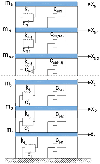
Consider N degree of freedom shear frame model with VDs. cadi which is shown Figure 1 expresses added VD at ith story while stationary random seismic ground acceleration having zero mean is represented by ẍg. The equation of motion of structure with added VDs system could be expressed as bellow
in which x(t), and are the displacement, velocity and acceleration vectors of shear frame model controlled with VDs. M, K, Cs represent NxN dimensional mass, stiffness and structural damping matrices, respectively. is the influence vector, Cad is the NxN dimensional added damping matrix. These matrices are expressed as follows
Structural damping determination in the structure includes many factors, accordingly, it cannot be easily defined. For simplicity, structural damping matrix Cs can be evaluated as mass proportional which is Cs = α Ms, stiffness proportional which is Cs = β Ks or a linear combination of mass and stiffness (Rayleigh damping) which is Cs = α Ms+β Ks. In here α and β are calculated in terms of the first and second normal mode of vibration. α and β coefficients can be calculated with the following equation.
Where ωs1, ωs2 first and second mode natural frequencies of the shear building, ξs1 and ξs2 are damping ratios with respect to first and second mode.
Fourier Transformation of Equation (1) is written as
Where X(ω) expresses the Fourier transform of the displacement of controlled structure and is the stationary ground acceleration with zero mean in the frequency domain. i denotes the imaginary unit. The damping matrix C includes both structural and added damping values. The equation above can be arranged as
in which A is
X(ω) can be rewritten as follows
X(ω) is defined with respect to displacement transfer function HD(ω) follow as
The matrix T transforms the displacement vector to the interstorey drift vector δ(ω). It can be given as
If Hδ(ω) is defined as interstorey drift transfer function, δ(ω) can be rewritten with respect to Hδ(ω) as follows
where Hδ(ω) denotes the transfer function of the interstorey drifts. Hδ(ω) is given as
As similar to the previous Equation (10), absolute acceleration in the frequency domain can be expressed as
where, HAA(ω) is the absolute acceleration transfer function. It can be expressed as:
By using the random vibration theory, the mean square of displacement ith floor can be defined as
where, Sg(ω) is Power Spectral Density (PSD) function of seismic input, |HDi(ω)| and |HAAi(ω)| are the transfer function amplitude of ith displacement and absolute acceleration, respectively. In these equations, ()* represents the complex conjugate. The above formulas have also been used by Takewaki (2009).
General Concept of Critical Excitation Method for Design
The general concept of probabilistic critical excitation method is explained herein (Takewaki, 2013). The seismic effect can be defined as a critical excitation. The natural frequencies of the structures are taken into consideration. When the dominant frequency of ground motion and the natural frequency of structure coincide, devastating damage can occur on the structure due to the resonance effect (Takewaki, 2013). Because of the high level of uncertainty of the ground motion, its prediction and identification are quite difficult. Therefore, probabilistic critical excitation method (Takewaki, 2013) can be highly powerful for this specification. According to this method, the definition of power limit is given as follow (Takewaki, 2013)
In the inequality equation, PSD function Sg(ω) can be explained as input variance and is the power limit that is the area limit of PSD function. The amplitude limit of Sg(ω) is defined as Takewaki (2013)
where is the supremum of PSD function Sg(ω). Taking into consideration of ground motion records, and can be defined. If almost reaches to infinity, PSD Sg(ω) can be evaluated as Dirac delta function. It is well-known that Dirac delta function takes extremely high values in very small intervals. When is considered as finite, the other solution of Sg(ω) is evaluated as a band-limited white-noise. The frequency interval Ω can be defined according to rate under the band-limited white-noise excitation. The upper and lower limits of ωu and ωL can be explained with respect to this rate (Takewaki, 2013).
Definition of Optimization Problem and Method
Using the random vibration theory, in order to obtain objective functions which is mean square of displacement can be expressed in a closed form
The passive and active constraints are defined with respect to upper and lower limits and total damping as follow
in which, , are upper bounds of added damping of ith added VD and total limit of added VDs, respectively.
Differential Evolution Algorithm for Vd Optimization
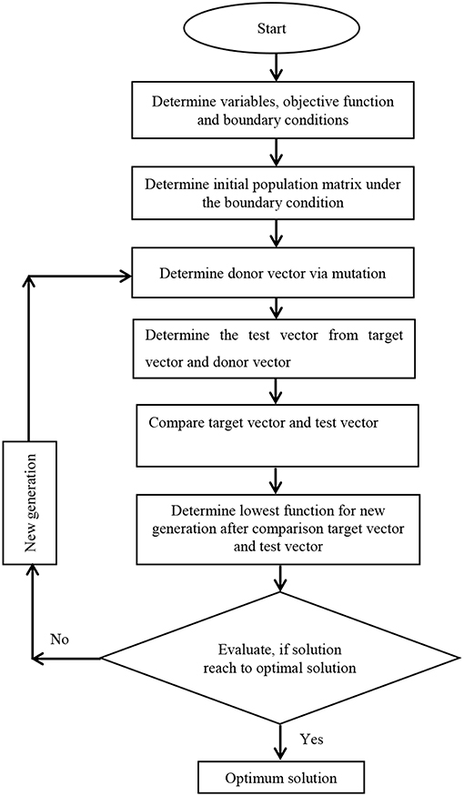
Although direct search methods spend relatively more computation time, their tolerance with respect to noise is more robust (Champion and Strzebonski, 2008). For this reason, in this study, a kind of stochastic and direct search optimization method named as Differential Evolution (DE) is utilized. This method was developed by Storn and Price (1997). The objective function is defined under design constraints. Initial population matrix is composed considering the boundary conditions. In the first step, the donor vector is composed of exposure to mutation. In the second step, target and donor vectors create the test vector. In the third step, for the purpose of picking up the new generation, target and test vectors are compared to determine the lowest one. In the fourth step, if the optimal solution is evolved, DE procedure is ended. Otherwise, it is returning to the mutation step to evaluate the new generation. These steps are formulated and expressed as follows (Peñuñuri et al., 2011; Wu et al., 2018; Biswar et al., 2019).
In the case of gth generation consideration, ith target vector can be defined as
In this equation, NP means the number of populations and the dimension of the problem is symbolized by D which is usually evaluated in between 2D and 40D (Ronkkonen et al., 2005).
In the population matrices, initialization at the first generation is set equal to zero (g = 0). The population matrix in zero generation is defined with respect to the jth component of ith vector as following
In this equation, randi, j(0, 1) is randomly chosen from uniformly distributed numbers which are between 0 and 1. In the equation above, i = 1, 2, 3,…, NP and j = 1, 2, 3,…, D. xj, Low and xj, up are the lower and upper limits of jth component which are mentioned as above for DE. Each step can be determined as follows
Step 1: Target vectors mutation and donor vectors creation
Random target vectors , and in which , ve [1, NP] are determined as stochastically for each target vector . These random vectors create the donor vectors via scaling factor F which is usually chosen between 0 and 1. Donor vector can be expressed as follows
Step 2: Crossover in order to compose the test vector
Crossover is exposed to donor vector in order to obtain the test vector as following
In this equation, jrand is chosen as random integer number which is between [1-D]. Cr is the crossover rate which is in between [0,1].
Step 3: Selection of superior one
Either target vector or test vector is selected as lowest one which is transferred to the next generation so that superior one is assigned as target vectors which is expressed as
If the optimum solution is obtained, the operation is ended. Otherwise, it is returned to the mutation step to compose the new generation. The steps explained above are shown as a flow chart in Figure 2. DE Algorithm is able to reach the optimum solution with vertical changes. It is a stochastic search algorithm and uses random numbers in every iteration. Therefore, the variation of the objective functions is non-monotonic. Unlike gradient-based methods, direct search methods do not use derivative information. Genetic Algorithm, Nelder-Mead, Simulated Annealing, and Differential Evolution may be given as some examples for the direct search methods. Although a direct search method needs more time for convergence, their tolerance to noises is more effective (Champion and Strzebonski, 2008). Differential Evolution based on a genetic algorithm that maintains a population of specimens, x1,…,xn, represented as vectors of real numbers (“genes”). Every iteration, each xi chooses random integers a, b, and c and constructs the mate yi = xi+γ(xa+(xb−xc)), where γ is the value of Scaling Factor. Then xi is mated with yi according to the value of Cross Probability, giving us the child zi. At this point, xi competes against zi for the position of xi in the population. Search Points is Min [10*d, 50], where d is the number of variables. Differential Evolution is quite robust but generally slower than other methods due to the relatively large set of points it maintains.
Numerical Example
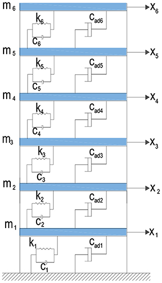
The optimum design and optimal distribution of VDs is executed for a sample 6 story shear building model which is shown in Figure 3 by using random vibration theory and probabilistic critical excitation method (Takewaki, 2013). The objective function, which is the mean square response of top floor displacements to be minimized, is chosen to find optimum VDs. The upper value of is set equal to the value that is calculated from the proposed method by Aydin (2013). If a VD at a specific story convergence to zero, it is set equal to zero. Therefore, VD placement is not carried out for this specific story. After the design is obtained, in order to understand the validity of the proposed method, the results are compared with the results of methods which are proposed by Takewaki (2000), Aydin (2013) and uniformly distributed VDs. The time history analyses are performed using El Centro (NS), Cape Mendocino (Petroli NS) and Kobe (NS) ground motions.
In the 6-story sample model, structural damping of the structure is supposed to be Rayleigh damping. First and second mode damping ratios ξ1 and ξ2 are set equal to 0.02, each floor mass and each story stiffness are taken as and respectively. Natural frequencies for the undamped case are calculated as ωsi = {3.48, 10.24, 16.40, 21.61, 25.56, 28.03}rad/s. Structural damping is evaluated as Rayleigh damping. It is given as
The upper limit of each VD is taken as , and total damper quantities of upper limit of VDs which is defined as obtained by Aydin (2013). Therefore, total damping quantities are restricted as In these limitations, the mean square of top floor displacements is minimized under the critical excitations to carry out optimum placements to floors and their optimal values.
In the example, in order to attain the critical excitation, power limit of power spectral density and amplitude limit are specified as and , respectively (Takewaki, 2013). These parameters belong to 40 s duration of the El Centro (NS) ground motion record (Takewaki, 2013). Frequency bandwidth Ω is identified as . Frequency ranges of critical excitation for two fundamental modes of lower and upper limits are obtained for the first mode as ωL1 = 1.38rad/s and ωu1 = 5.58rad/s, and for the second the mode as ωL2 = 8.13 rad/s, and ωu2 = 12.33 rad/s. First and second modes are considered for design. The PSD is taken as , and beyond the range, it is taken as zero. The performance of the structure-VDs system is tested in comparison with the results of Takewaki (2000), Aydin (2013) and uniformly distributed VDs considering El Centro (NS), Cape Mendocino (Petroli NS), Kobe (NS) ground motions.
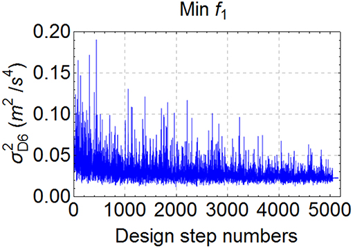
The variation of objective function (f1) during the optimization via differential evolution (DE) method under the specified constraints are depicted according to design step numbers in Figure 4. Calculated optimum VDs parameters and their allocation to floors according to objective functions and in comparison, with the methods in the literature (Takewaki, 2000; Aydin, 2013) and uniform distribution are depicted in Table 1. As seen in Table 1, although all total damper quantities are the same for all designs, the placements and properties of VDs are different from each other. For example, while VDs focus on to the first, second and also just a little bit to third floors with respect to f1 minimization, allocations focus on the first four floors on the basis of the f2 minimization. If the proposed method by Aydin (2013) is considered, VDs allocations focus on the first two stories but, most of VDs quantity focus on the first story. If the proposed method by Takewaki (2000) is considered, close quantity VDs are placed to first and second stories.
While the minimization of acceleration may be important for the elastic structures, the minimization of deformation may be important for the inelastic structures. Therefore, the objective functions which are needed are chosen by engineers considering objectives. In this study, only one objective function is evaluated. In addition to this, three different ground motions are considered for the time history analysis. These ground motions are El Centro (NS), Cape Mendocino (Petrolia NS), and Kobe (NS) ground motions, respectively. Taking into consideration of damage in the structure, whereas the response of the inelastic structure is usually important for the displacements (or deformations), the acceleration or stress response are more important for the non-structural elements and non-structural components in the structures (Viti et al., 2006).
The variation of the transfer function amplitude of top displacement |HD6(ω)|, the transfer function amplitude of top absolute acceleration |HAA6(ω)| and the transfer function amplitude of first interstorey drift |Hδ1(ω)| are shown in Figure 5 with respect to the objective function which are the mean square of top floor displacement and methods in literature which are proposed by Takewaki (2000) and Aydin (2013), lastly on basis of uniformly distributed viscous damper to each floors. As seen in these Figures, proposed methods are very effective in reducing all these transfer functions for both the first mode and second mode control. They are effective to decrease the response of the structure and consistent to each other and all methods here are very effective in reducing the response but each method has individually superior to each other for a different kind of reduction. Table 2 also shows the response reductions of structure for all methods with respect to three different ground motions which are El Centro (NS), Cape Mendocino (Petrolia NS) and Kobe (NS) ground motions.
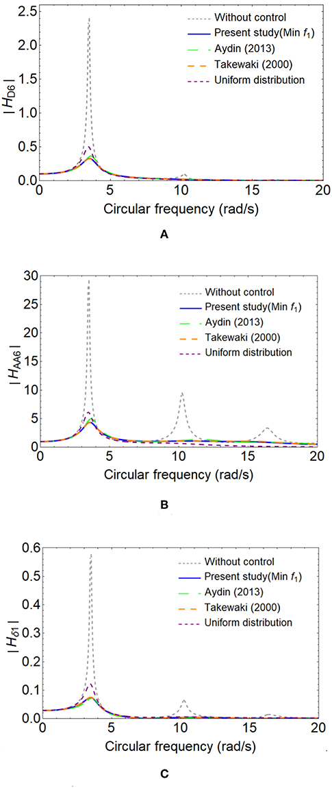
Figure 5. Frequency responses of 6th floor with respect to the transfer function amplitude of top displacement |HD6| (A), the transfer function amplitude of top absolute acceleration |HAA6| (B) and the transfer function amplitude of first floor inter story drift |Hδ1| (C) considering objective function f1, the methods of Aydin (2013), Takewaki (2000), and uniformly distributed VDs.
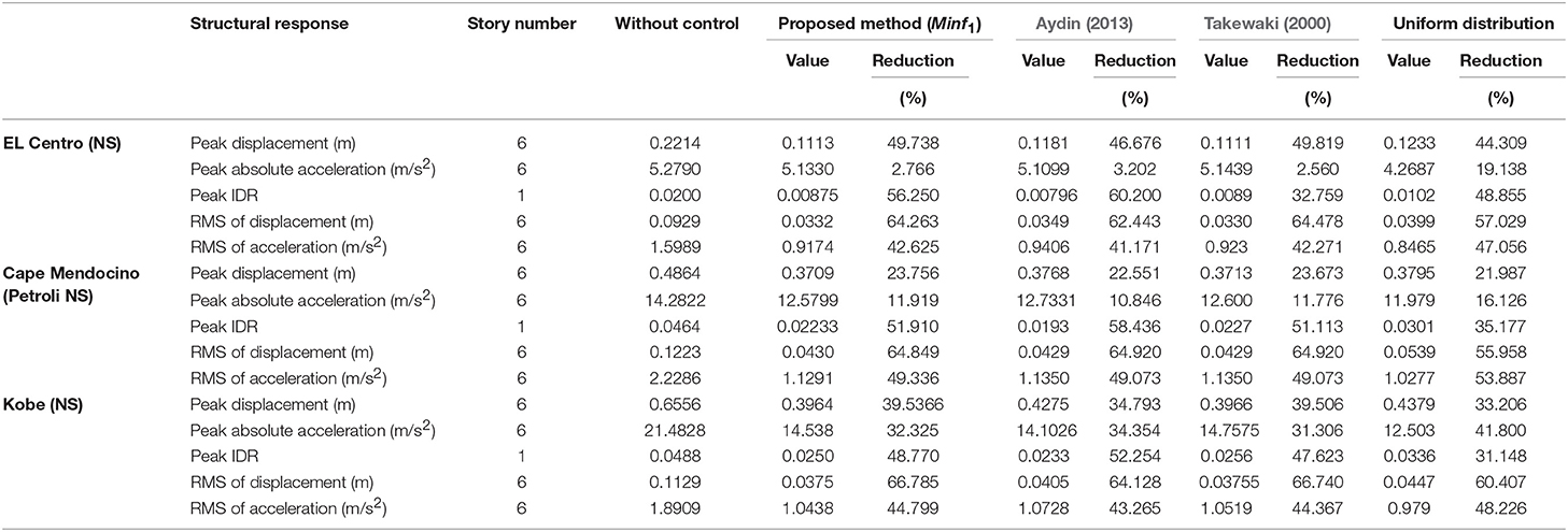
Table 2. Comparison of the results of proposed methods with the other methods for different ground motions.
Figures 6A–E show response of the floors of the shear building with respect to peak displacements, peak accelerations, peak interstorey drifts ratio (IDR), root mean square (RMS) of displacements and root mean square (RMS) of accelerations, respectively under the El Centro (NS) ground motion. As seen in these figures, although all methods and uniform distribution are effective to decrease the response of the structure and consistent to each other and all methods here are very effective in reducing the response, therefore each method have individually superior to each other for a different kind of reduction. Table 2 also shows the responses and response reductions of structure for all methods with respect to three different ground motions which are El Centro (NS), Cape Mendocino (Petrolia NS) and Kobe (NS) ground motions.
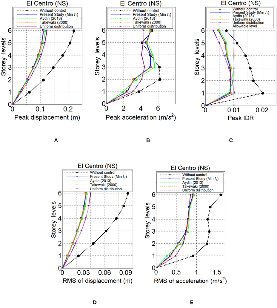
Figure 6. Peak displacements (A), peak absolute accelerations (B), peak IDR (C), RMS of displacements (D), RMS of accelerations (E) based on f1 and the methods of Aydin (2013), Takewaki (2000) and uniformly distributed VDs for El Centro (NS) ground motion.
Three different ground motions are selected for time history analysis. Table 3 shows the percentage of Arias intensity in different frequency ranges to the total intensity for near-field ground motion (Moustafa and Takewaki, 2010). As it is seen this table, Kobe (NS) ground motion has narrow frequency bandwidth. In the comparison of El Centro (NS) and Cape Mendocino (Petrolia NS) ground motions have more wide-width frequency range than Kobe (NS). It is observed that the peak acceleration response of example structure in this study, lessen if the ground motion has more wide frequency range. For example, as seen Table 2, the peak acceleration response reduction at 6th floor of the shear building, the highest for Kobe (NS) ground motion which has the narrowest frequency range in this study. In the table, peak acceleration reduction at the top floor is for El Centro (NS) ground motion 2.766 %, for Cape Mendocino (Petrolia NS) ground motion 11.919 % and for Kobe (NS) 32.325 % ground motion with respect to VDs of mean square of top floor displacement minimization. It can be concluded this results that, VDs could be more effective in reducing the peak acceleration response for against to ground motions which have narrower band frequency content. In addition to this case, it is concluded in the literature that VDs are not much effective to reduce the peak acceleration for the inelastic structures (Reinhorn et al., 1995). Whereas VDs are effective in reducing the displacement of the inelastic structures, they are effective to reduce the acceleration of the elastic structures (Viti et al., 2006).
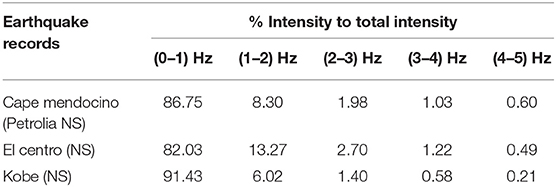
Table 3. Percentage of Arias intensity in different frequency ranges to the total intensity for near-field ground motion (Moustafa and Takewaki, 2010).
For the purpose of plotting the 3D graphics are plotted to observe the variations of the absolute value of transfer functions with respect to excitation frequencies and added viscous dampers (cadi). If f1 minimization is considered, three numbers of VDs are needed and they are placed to first three floors. As seen in Figures 7–9, while viscous damper located to the first floor is considered, for the response reduction on transfer function, the total VDs located in other stories is kept stable. As understood from these 3D figures, the response reduction of the absolute value of displacement, absolute acceleration and first story inter-story drift transfer functions are obtained in a better way with the help of cad1, cad2, cad3, and cad4 successively. After the decrease of the transfer function amplitude reaches the optimum point in 3D graphics, this value of transfer function continues almost as stable value, even if cadi value is raised to higher values in these plots.

Figure 7. 3D plots of the absolute value of transfer function |HD6| based on f1 minimization with respect to excitation frequency and added damping parameters.

Figure 8. 3D plots of the absolute value of transfer function |HAA6| based on f1 minimization with respect to excitation frequency and added damping parameters.

Figure 9. 3D plots of the absolute value of transfer function |Hδ6| based on f1, minimization with respect to excitation frequency and added damping parameters.
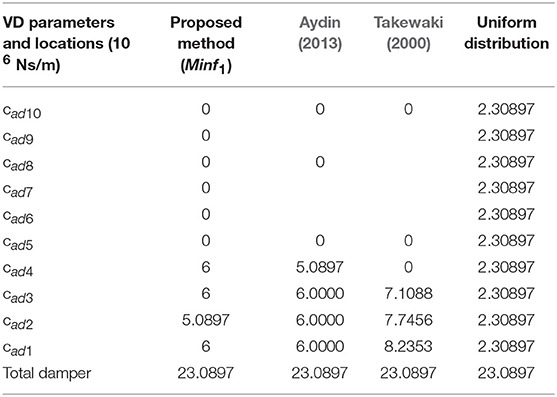
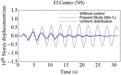
Even if f1 function could not decrease acceleration responses as seen in Table 2, it has better results with respect to displacements responses. In this study a 10-story shear frame is also detected in order to understand the effectiveness of the f1 function. In this 10-story shear frame, each floor mass and stiffness are taken as and and damping coefficient chosen as respectively. The calculated VDs and their location to stories are depicted in Table 4. The responses of the added viscous damper which is designed with respect to f1 function are shown in Table 5, designed compared with other methods in literature and uniformly distributed viscous dampers for El Centro (NS) ground motion. In addition to this, the time history of top floor displacements responses of the f1 function and uniformly distributed viscous damper is added to the manuscript as seen in Figure 10. It is observed from the Table 5 and Figure 10, f1 function is more successful than the uniformly distributed viscous damper design with respect to displacement minimization and reduction of accelerations responses between these designs is almost close the each other. The other advantage of f1 function beside of succession of displacement reduction. While the design with uniformly distributed VDs occupies ten stories, VDs which is designed according to f1 function needs only four stories locations. This means design based on f1function needs less workmanship cost than the uniformly distributed VDs design.

Table 5. Comparison of the results of proposed methods with the other methods for the 10-story shear frame with respect to El Centro ground motion.
Conclusions
A damper optimization method is proposed for building structures using random vibration theory in the frequency domain. Differential Evolution (DE) algorithm is used in order to minimize the objective function which is the top floor displacement function considering design constraints. After the optimal design is found, the three different ground motions are conducted to test the seismic response of model building structure. Additionally, the proposed optimal design method is compared with the other methods in the literature which were proposed by Aydin (2013), Takewaki (2000) and the uniform design. Some conclusions could be summarized as follows:
(1) It is observed that optimum designed and placed VDs can decrease the transfer function amplitudes effectively.
(2) The proposed method is very effective in reducing seismic response and is compatible with the other methods in the literature.
(3) The method used for each objective function minimizes its purpose better. The different purpose functions can be important for different types of structures. In this study, the application objective function is shown on a single type of structure.
(4) It is concluded that differential evolution (DE) algorithm can be used to solve the optimal damper problem based on transfer functions by considering critical excitation.
(5) The proposed method is very effective for more than one mode of control in the frequency domain.
(6) The objective function for the proposed method is more successful than uniformly distributed VDs design with respect to displacement minimization. Additionally, design based on f1 function needs less workmanship cost than the uniformly distributed VDs design.
Data Availability
The datasets generated for this study are available on request to the corresponding author.
Author Contributions
EA, HC, and BO contributed to the concept and idea of the paper. The analyses were carried out by EA and HC. All three authors contributed to organize, write, review, and approve the submitted version.
Conflict of Interest Statement
The authors declare that the research was conducted in the absence of any commercial or financial relationships that could be construed as a potential conflict of interest.
References
Adachi, F. S., Yoshitomi, S., Tsuji, M., and Takewaki, I. (2013). Nonlinear optimal oil damper design in seismically controlled multi-story building frame. Soil Dyn. Earthquake Eng. 44, 1–13. doi: 10.1016/j.soildyn.2012.08.010
Agrawal, A. K., and Yang, J. N. (1999). Design passive energy dissipation systems based on LQR methods. J. Intell. Mater. Syst. Struct. 10:12. doi: 10.1106/FB58-N1DG-ECJTB8H4
Agrawal, A. K., and Yang, J. N. (2000). Optimal placement of passive dampers on buildings using combinatorial optimization. J. Intell. Mater. Syst. and Struct. 10, 997–1014. doi: 10.1106/YV3B-TP5H-HWQ2-X1OK
Akehashi, H., and Takewaki, I. (2019). Optimal viscous damper placement for elastic-plastic MDOF Structures under critical double impulse. Front. Built Environ. doi: 10.3389/fbuil.2019.00020
Aydin, E. (2013). A simple damper optimization algorithm for both target added damping ratio and interstorey drift ratio. Earthquake Struc. 5, 83–109. doi: 10.12989/eas.2013.5.1.083
Aydin, E., Ozturk, B., and Dutkiewicz, M. (2019). Analysis of efficiency of passive damper in multistorey buildings. J. Sound Vib. 439, 17–28. doi: 10.1016/j.jsv.2018.09.031
Bishop, J. A., and Striz, A. G. (2004). On using genetic algorithms for optimum damper placement in space trusses. Struct. Multidisc Optim. 28, 2–3. doi: 10.1007/s00158-004-0441-9
Biswar, P. P., Sugantan, P. N., Wu, G., and Amaragunta, G. A. J. (2019). Parameter estimation of solar cells using datasheet information with the application of an adaptive differential evolution algorithm. Renew. Energy 132, 435–438. doi: 10.1016/j.renene.2018.07.152
Bogdanovic, A., and Rakicevic, Z. (2019). Optimal damper placement using combined fitness function. Front. Built Environ. 5:4. doi: 10.3389/fbuil.2019.00004
Cao, X., and Mlejnek, H. P. (1995). Computational prediction and redesign for visco-elastically damped structures. Comput Methods Appl. Mech. Eng. 125, 1–4. doi: 10.1016/0045-7825(95)00798-6
Cetin, H., Aydin, E., and Ozturk, B. (2017). Optimal damper allocation in shear buildings with tuned mass dampers and viscous dampers. Int. J. Earthquake Impact Eng. 2, 89–120. doi: 10.1504/IJEIE.2017.089038
Champion, B., and Strzebonski, A. (2008). Constrained Optimization. Champaign, IL: Wolfram Mathematica Tutorial Collection.
Constantinou, M. C., and Tadjbakhsh, I. G. (1983). Optimum design of a first storey damping. Comput. Struct. 17, 305–310. doi: 10.1016/0045-7949(83)90019-6
Dargush, G. F., and Sant, R. S. (2005). Evolutionary aseismic design and retrofit of structures with passive energy dissipation. Earthq. Eng. Struct. Dyn. 34, 1601–1626. doi: 10.1002/eqe.497
De Domenico, D., and Ricciardi, G. (2019). Earthquake protection of structures with nonlinear viscous dampers optimized through an energy-based stochastic approach. Eng. Struct. 179, 523–539. doi: 10.1016/j.engstruct.2018.09.076
De Domenico, D., Ricciardi, G., and Takewaki, I. (2019). Design strategies of viscous dampers for seismic protection of building structures: a review. Soil. Dyn. Earthquake Eng. 118, 144–165. doi: 10.1016/j.soildyn.2018.12.024
Fujita, K., Kasagi, M., Lang, Z. Q., Penfei, G., and Takewaki, I. (2014), Optimal placement design of nonlinear dampers for building structures in the frequency domain. Earthq. Struct. 7, 1025–1044. doi: 10.12989/eas.2014.7.6.000
Gluck, N., Reinhorn, A. M., Gluck, J., and Levy, R. (1996). Design of supplemental dampers for control of structure. J. Struct. Eng. 122, 1394–1399. doi: 10.1061/(ASCE)0733-9445(1996)122:12(1394)
Gurgoze, M., and Muller, P. C. (1992). Optimum position of dampers in multi body systems. J. Sound Vib. 158, 517–530. doi: 10.1016/0022-460X(92)90422-T
Hahn, G. D., and Sathiavageeswara, K. D. (1992). Effects of added-damper distribution on the seismic response of building. Comput. Struct. 43, 941–950. doi: 10.1016/0045-7949(92)90308-M
Hart, G., and Wong, K. (2000). Structural Dynamics for Structural Engineers. New York, NY: John Wiley & Sons Ltd.
Hwang, J. S., Min, K. W., and Hong, S. M. (1995). Optimal design of passive viscoelastic dampers having active control effect for building structures. Trans. Korean Soc. Noise Vib. Eng. 5, 225–234.
Lang, Z. Q., Guo, P. F., and Takewaki, I. (2013), Output frequency response function based design of additional nonlinear viscous dampers for vibration control of multi-degree-of-freedom systems. J. Sound Vib. 332, 4461–4481. doi: 10.1016/j.jsv.2013.04.001
Lavan, O., Cimellaro, G. P., and Reinhorn, A. M. (2008), Noniterative optimization procedure for seismic weakening damping of inelastic structures. J. Struc. Eng. 134, 1638–1648. doi: 10.1061/(ASCE)0733-9445(2008)134:10(1638)
Loh, C. H., Lin, P. Y., and Chung, N. H. (2000). Design of dampers for structures based on optimal control theory. Earthq. Eng. Struct. Dyn. 29, 1307–1323. doi: 10.1002/1096-9845(200009)29:9<1307::AID-EQE972>3.0.CO;2-D
Lopez Garcia, D., and Soong, T. T. (2002). Efficiency of a simple approach to damper allocation in MDOF structures. J. Struct. Control. 9, 19–30. doi: 10.1002/stc.3
Moustafa, A., and Takewaki, I. (2010). Deterministic and probabilistic representation of near-field pulse-like ground motion. Soil Dyn. Earthquake Eng. 292, 412–422. doi: 10.1016/j.soildyn.2009.12.013
Palermo, M., Silvestri, S., Landi, L., Gasparini, G., and Trombetti, T. (2018). A “direct five-step procedure” for the preliminary seismic design of buildings with added viscous dampers. Eng. Struct. 173, 933–950. doi: 10.1016/j.engstruct.2018.06.103
Peñuñuri, F., Peón-Escalante, R., Villanueva, C., and Pech-Oy, D. (2011). Synthesis of mechanisms for single and hybrid tasks using differential evolution. Mech. Mach. Ther. 46, 1335–1349. doi: 10.1016/j.mechmachtheory.2011.05.013
Reinhorn, A. M., Li, C., and Constantinou, M. C. (1995). Experimental and Analytical Investigation of Seismic Retrofit of Structures with Supplemental Damping: Part 1 – Fluid Viscous Damping Devices, Technical Report NCEER-95-0001, National Center for Earthquake Engineering Research, University at Buffalo (SUNY), (Buffalo, NY).
Ronkkonen, J., Kukkonen, S., and Price, K. V. (2005). “Real-parameter optimization with differential evolutionm,” in IEEE Congress on Evolutionary Computation. 506–513.
Shukla, A. K., and Datta, T. K. (1999). Optimal use of viscoelastic dampers in building frames for seismic force. J. Struct. Eng. ASCE 125, 401–409. doi: 10.1061/(ASCE)0733-9445(1999)125:4(401)
Silvestri, S., Gasparini, G., and Trombetti, T. (2010), A five-step procedure fort the dimensioning of viscous damper to BE inserted in building. J. Earthquake Eng. 14, 417–447. doi: 10.1080/13632460903093891
Sonmez, M., Aydin, E., and Karabork, T. (2013). Using an artificial bee colony algorithm for the optimal placement of viscous dampers in planar building frames. Struct. Multidisc. Optim. 48, 395–409. doi: 10.1007/s00158-013-892-y
Storn, R., and Price, K. V. (1997). Differential evolution—a simple and efficient the heuristic for global optimization over continuous spaces. J. Global Optimiz. 11, 341–359. doi: 10.1023/a:1008202821328
Takewaki, I. (1997a), Efficient redesign of damped structural systems for target transfer functions. Comput. Methods Appl. Mech. Eng. 147, 275–286. doi: 10.1016/S0045-7825(97)00022-4.
Takewaki, I. (1997b), Optimal damper placement for minimum transfer functions. Earthq. Eng. Struc. Dyn. 26, 1113–1124. doi: 10.1002/(SICI)1096-9845(199711)26:11<1113::AID-EQE696>3.0.CO;2-X.
Takewaki, I. (1999a), Non-monotonic optimal damper placement via steepest direction search. Earthq. Eng. Struc. Dyn. 28, 655–670. doi: 10.1002/(SICI)1096-9845(199906)28:6<655::AID-EQE833>3.0.CO;2-T.
Takewaki, I. (1999b), Displacement-acceleration control via stiffness-damping collaboration. Earthq. Eng. Struc. Dyn. 28. doi: 10.1002/(SICI)1096-9845(199912)28:12<1567::AIDEQE882>3.0.CO;2-1.
Takewaki, I. (2000), Optimum damper placement for planar building frames using transfer functions. Struct. Multidisc. Optim. 20, 280–287. doi: 10.1007/s001580050158.
Takewaki, I. (2009). Building control with passive dampers: Optimal Performance-Based Design for Earthquakes. Singapore: John Wiley & Sons Ltd. (Asia).
Takewaki, I. (2013). Critical Excitation Methods in Earthquake Engineering. Oxford: Elsevier Science.
Trombetti, T., and Silvestri, S. (2006), On the modal damping ratios of shear-type structures equipped with Rayleigh damping systems. J. Sound Vib. 292, 21–58. doi: 10.1016/j.jsv.2005.07.023
Tsuji, M., and Nakamura, T. (1996). Optimum viscous dampers for stiffness design of shear buildings, Struct. Desig. Tall Build. 5, 217–234. doi: 10.1002/(SICI)1099-1794(199609)5:3<217::AID-TAL70>3.0.CO;2-R
Viti, S., Cimellaro, G. P., and Reinhorn, A. M. (2006), Retrofit of a hospital through strength reduction enhanced damping. Smart Struct. Syst. 2, 339–355. doi: 10.12989/sss.2006.2.4.339
Wu, G., Shen, X., Li, H., Chen, H., Lin, A., and Sugantan, P. N. (2018). Ensemble of differential evolution variants. Inform. Sci. 423, 172–186. doi: 10.1016/j.ins.2017.09.053
Yang, J. N., Lin, S., Kim, J. H., and Agrawal, A. K. (2002), Optimal design of passive energy dissipation systems based on H∞ H2 performances. Earthq. Eng. Struct. Dyn. 31, 921–936. doi: 10.1002/eqe.130
Keywords: differential evolution algorithm, viscous dampers (VDs), optimal viscous damper design, viscous damper placement, passive control, critical excitation
Citation: Cetin H, Aydin E and Ozturk B (2019) Optimal Design and Distribution of Viscous Dampers for Shear Building Structures Under Seismic Excitations. Front. Built Environ. 5:90. doi: 10.3389/fbuil.2019.00090
Received: 27 February 2019; Accepted: 19 June 2019;
Published: 12 July 2019.
Edited by:
Dario De Domenico, University of Messina, ItalyReviewed by:
Diego Lopez-Garcia, Pontifical Catholic University of Chile, ChileMichele Palermo, University of Bologna, Italy
Copyright © 2019 Cetin, Aydin and Ozturk. This is an open-access article distributed under the terms of the Creative Commons Attribution License (CC BY). The use, distribution or reproduction in other forums is permitted, provided the original author(s) and the copyright owner(s) are credited and that the original publication in this journal is cited, in accordance with accepted academic practice. No use, distribution or reproduction is permitted which does not comply with these terms.
*Correspondence: Baki Ozturk, YmFraW96dHVya0BoYWNldHRlcGUuZWR1LnRy
 Huseyin Cetin
 Ersin Aydin
 Baki Ozturk