- 1College of Mechanical and Electrical Engineering, Nanjing University of Aeronautics and Astronautics, Nanjing, China
- 2College of Mechanical and Electrical Engineering, Hohai University, Changzhou, China
- 3Department of Mechanical Engineering, City University of Hong Kong, Kowloon, Hong Kong SAR, China
Robot-assisted rehabilitation has exhibited great potential to enhance the motor function of physically and neurologically impaired patients. State-of-the-art control strategies usually allow the rehabilitation robot to track the training task trajectory along with the impaired limb, and the robotic motion can be regulated through physical human-robot interaction for comfortable support and appropriate assistance level. However, it is hardly possible, especially for patients with severe motor disabilities, to continuously exert force to guide the robot to complete the prescribed training task. Conversely, reduced task difficulty cannot facilitate stimulating patients’ potential movement capabilities. Moreover, challenging more difficult tasks with minimal robotic assistance is usually ignored when subjects show improved performance. In this paper, a control framework is proposed to simultaneously adjust both the training task and robotic assistance according to the subjects’ performance, which can be estimated from the users’ electromyography signals. Concretely, a trajectory deformation algorithm is developed to generate smooth and compliant task motion while responding to pHRI. An assist-as-needed (ANN) controller along with a feedback gain modification algorithm is designed to promote patients’ active participation according to individual performance variance on completing the training task. The proposed control framework is validated using a lower extremity rehabilitation robot through experiments. The experimental results demonstrate that the control scheme can optimize the robotic assistance to complete the subject-adaptation training task with high efficiency.
1 Introduction
Due to the rapidly increasing number of physically and neurologically impaired patients around the world, rehabilitation robots have been developed to assist in the therapeutic training of impaired limbs, which improves rehabilitation efficiency and saves human labor through highly autonomous assistance (Xu et al., 2020a; Xu et al., 2020b). The control strategy of a rehabilitation robot significantly influences rehabilitation efficacy. Most clinical cases enable physiotherapists to feed the task trajectories into the robot controller before rehabilitation starts. However, patients can only modify the robot’s current trajectory through physical human-robot interaction (pHRI) without affecting the future task trajectory. Particularly for patients with severe impairment, it is hardly possible to continuously exert adequate force to change the robot’s movement trajectory for a period, and their recovery, comfort, and safety cannot be guaranteed accordingly. Therefore, online adaptation of desired trajectories to patients’ performance is indeed necessary. Dynamic movement primitive (DMP) (Schaal, 2006) and central pattern generator (CPG) (Sproewitz et al., 2008) are two common tools for trajectory generation, and they have been applied in rehabilitation robotics research (Luo et al., 2018; Yuan et al., 2020). In (Xu et al., 2023), coupled cooperative primitives are formulated, where pHRI is expressed as a first-order impedance model and assumed as a modulation term in DMP. The problems existing in tuning the impedance model parameters have been explained above. The human-robot interaction energy is combined with adaptive CPG dynamics to plan gaits for exoskeletons (Sharifi et al., 2021); however, this introduces many uncertain parameters, the resolution of which is time-consuming. In addition, it is found that the robot’s desired trajectory can be deformed in response to subject actions (Lasota and Shah, 2015), but it is unclear which deformed trajectory is optimal. The robot’s future desired trajectory can be modified, and the optimal solution of the trajectory deformation is derived by detecting the human-robot interaction force (Losey and O’Malley, 2018). Similarly, trajectory deformation is applied to robotic rehabilitation, where a position controller is adopted to track the deformed trajectory, ignoring the rehabilitation effectiveness of the AAN training (Zhou et al., 2021). Apart from movement trajectory planning, users’ voluntary participation should be stimulated by adjusting the robotic assistance.
Additionally, passive control is usually employed to drive impaired limbs to move along the predefined task trajectory, where the active participation of patients cannot be encouraged to stimulate motor function recovery (Hogan et al., 2006). To overcome this problem, the assist-as-needed (AAN) control strategy is introduced to adapt the robotic assistance to the patients’ performance (Marchal-Crespo and Reinkensmeyer, 2009). An impedance/admittance control scheme is a common solution for addressing the physical relationship between humans and robots. An impedance controller based on a virtual tunnel regulates the robotic assistance while responding to the tracking error between the current trajectory and the desired trajectory (Krebs et al., 2003). A torque tracking impedance controller is proposed for lower limb rehabilitation robotics to generate assistance while ensuring acceptable trajectory deviation (Shen et al., 2018). An admittance control incorporating electromyography (EMG) signals is developed to improve human-robot synchronization (Zhuang et al., 2019). Both impedance and admittance control can regulate the relationship between the trajectory deviation and interaction effect by tuning the inertia-damping-stiffness parameters. In fact, different patients or even the same patient at different rehabilitation stages can exhibit varying motor capabilities; so, accurate determination of these parameters is essential to realize AAN training for different subjects and tasks. Furthermore, as for practical application in rehabilitation, dynamic human force and uncertain external disturbances often occur and cannot be measured intuitively and accurately. Both inappropriate impedance/admittance parameters and unknown dynamic interactive environments can lead to unstable and oscillating robot behaviors, which may decrease motion smoothness and even threaten human safety (Ferraguti et al., 2019). Furthermore, current AAN controllers are designed to provide only the necessary robotic assistance to complete the prescribed training task, which is not suitable for encouraging patients to challenge themselves with more difficult tasks and stimulate their potential motor capabilities for improved rehabilitation efficacy.
In this article, a control framework is proposed for the simultaneous adaptation of training tasks and robotic assistance according to patient performance. The main contributions of this article are listed as follows.
(1) A trajectory deformation algorithm is developed to plan the robot’s desired trajectory as the high-level controller, where the continuity, smoothness, and compliance of the robotic motion are achieved in response to the subject’s biological performance.
(2) An AAN control strategy with a feedback gain modification algorithm is employed to regulate the robotic assistance as the low-level controller. The controller is designed to encourage active participation by learning the patient’s residual motor capabilities and accurately tracking the deformed trajectory.
(3) Both the training task and robotic assistance adaptation algorithms are integrated into a framework to realize human-in-the-loop optimization, and this control framework is validated using a lower extremity rehabilitation robot.
The remainder of the article is organized as follows. The biological signal processing is described in Section 2. The trajectory generation is presented in Section 3, and the subject-adaptive AAN controller is explained in Section 4. The proposed control framework is verified through experiments in Section 5. Finally, this study is concluded in Section 6.
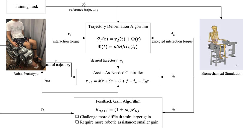
The schematic view of the proposed control framework is presented in Figure 1, and the detailed explanation is elaborated in the following sections.
2 Biological signal processing
For rehabilitation, robotic motions should be regulated by adapting to the user’s muscle strength, which can be derived from the human skin surface EMG signals. In this section, the EMG-driven musculoskeletal model for torque estimation is presented. EMG sensors (ETS FreeEMG300) are used to measure EMG signals, and the electrodes are attached to the relevant skin surface. Specifically, in the application of lower extremity rehabilitation, six electrodes are attached to gluteus maximus, semimembranosus, biceps femoris iliopsoas, sartorius, and rectus femoris for hip flexion/extension; six electrodes are attached to rectus femoris, vastus medialis, vastus lateralis, biceps femoris, semimembranosus, and semitendinosus for knee flexion/extension. The raw EMG signals are sampled at 1,024 Hz, bandpass filtered from 10 Hz to 500 Hz, and then notch filtered at 50 Hz to remove noise. The muscle activation is calculated by the neural activation function as
where
Subsequently, a Hill-typed muscle model is constructed to describe the relationship between muscle activation and muscle force (Yao et al., 2018). The force produced by the muscle-tendon unit
where
where
where
In the proposed EMG-driven musculoskeletal model, it is essential to determine the model parameters, i.e., the shape factor
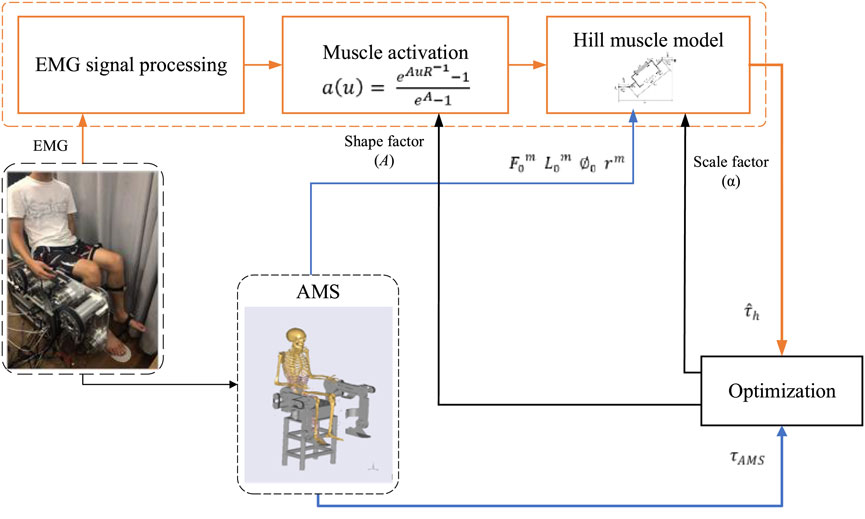
The optimization procedure is illustrated in Figure 2. The processed EMG signals are converted to muscle activation using (2) including the uncertain shape factor A. Then the muscle contraction model (Yao et al., 2018) is established to calculate the muscle-tendon force and the muscle torque through Equations 2–5, where the muscle-tendon length
where N is the number of samples. The Broyden–Fletcher–Goldfarb–Shanno algorithm (Peña et al., 2019), together with a penalty barrier algorithm, is employed to find the optimal parameters.
3 Trajectory adaptation
Prior to operating the rehabilitation robot, the training task needs to be predetermined by feeding the reference trajectory (task trajectory) into the robot controller, which is usually the natural gait trajectory of healthy subjects. The patient is then encouraged to complete the task with robotic assistance. Once the reference trajectory is preset and fed into the robot controller, however, it is not reasonable to maintain the task difficulty invariant throughout the rehabilitation procedure. In order to ensure the smoothness and compliance of the robotic motion, the robot’s desired trajectory should be modified intuitively and continuously in response to the human force (Losey and O’Malley, 2018). In this regard, the physical human-robot interaction (pHRI) should alter not only the robot’s current state but also its future behavior. In this section, a trajectory deformation algorithm is studied to explore the pHRI influence on the training task, and the modification is made on the original reference trajectory, generating the desired trajectory for the further controller design.
The reference trajectory (predetermined before the training) is defined as
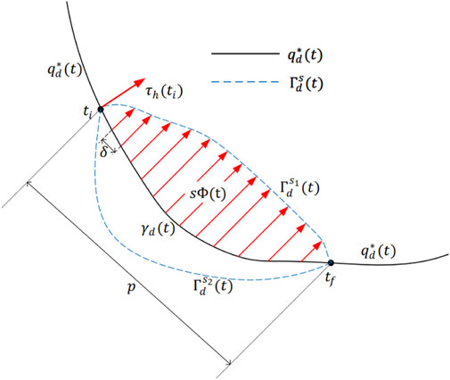
Apparently, deformed from the reference trajectory may follow different curves to shape
where
When the subject starts to exert force at time
Once
Comparing (7) with (8), the vital factor that causes the trajectory deformation can be formulated as a vector field function
The vector field function
where
The parameter
Combining (9), (10), (11), and (12), the relationship between the vector field function and the interaction torque is clarified, and the deformed trajectory is thus obtained as
After
4 Assist-as-needed controller
Based on the abovementioned trajectory generation scheme, an actuation controller needs to be designed to track the desired trajectory. More importantly, in response to various motor capabilities of different patients, a subject-adaptive controller is required to realize AAN training. In this section, an AAN control strategy along with a feedback gain modification algorithm is proposed to complete the training task motion and provide the minimum required assistance to encourage patients’ active engagement.
The robot dynamics in joint space can be presented as follows whilst considering pHRI.
where
Although the robot dynamics have been modeled as (14), it is impossible to accurately formulate disturbances that may decrease the compliance of robotic motion and the safety of pHRI. The total disturbances
where
where
where
Through the stability analysis in Appendix 1, we can conclude that the proposed control system yields a tracking error with uniformly ultimately bounded stability. The ultimate bound on the tracking error
where
Since the inertia matrix
where
Noticeably, the feedback gain
Situation 1: When the patient with severe motor disability has difficulty in completing the training task or learning a motion, increasing the value of
Situation 2: When the patient attempts to stimulate muscle strength to challenge themselves with more difficult tasks, decreasing the value of
Therefore, the selection of the feedback gain
A parameter
where
where
Combining the AAN controller (17) with the feedback gain modification algorithm (21) and (22), the control framework can provide a highly efficient and autonomous training strategy for robot-assisted rehabilitation.
5 Experiments
In order to validate the proposed control framework, the lower extremity rehabilitation robot mentioned in Xu et al. (2019), Xu et al. (2021) was utilized to conduct a series of experiments. The experiments were carried out on three healthy subjects. All subjects were informed of the detailed operation procedures and potential risks and signed consent forms before participation. The experiments were approved by the ethics committee of Hefei Institutes of Physical Science, Chinese Academy of Sciences (approval number: IRB-2019-0018). Two DOFs of the robot, including hip flexion/extension and knee flexion/extension, were involved in the training. Before operation, the reference trajectories were prescribed by physiotherapists to ensure rhythmic and comfortable training motion, and they were then fed into the robot controller. During the training, the subjects were asked to track the reference trajectories with the assistance of the rehabilitation robot actuation. Once the interaction force exerted by the subjects was detected by sensors, the reference trajectory was deformed to generate another optimal desired trajectory, and the robot was controlled to cooperate with the subject to complete the modified task motion. It should be noted that the subjects were not allowed to voluntarily move in the opposite direction from the task trajectory for accurate calculation of the deformed trajectory and safety guarantee.
Three groups of experiments were performed for the three subjects, and three different reference trajectories were configured. The time interval between the consecutive waypoints was set at
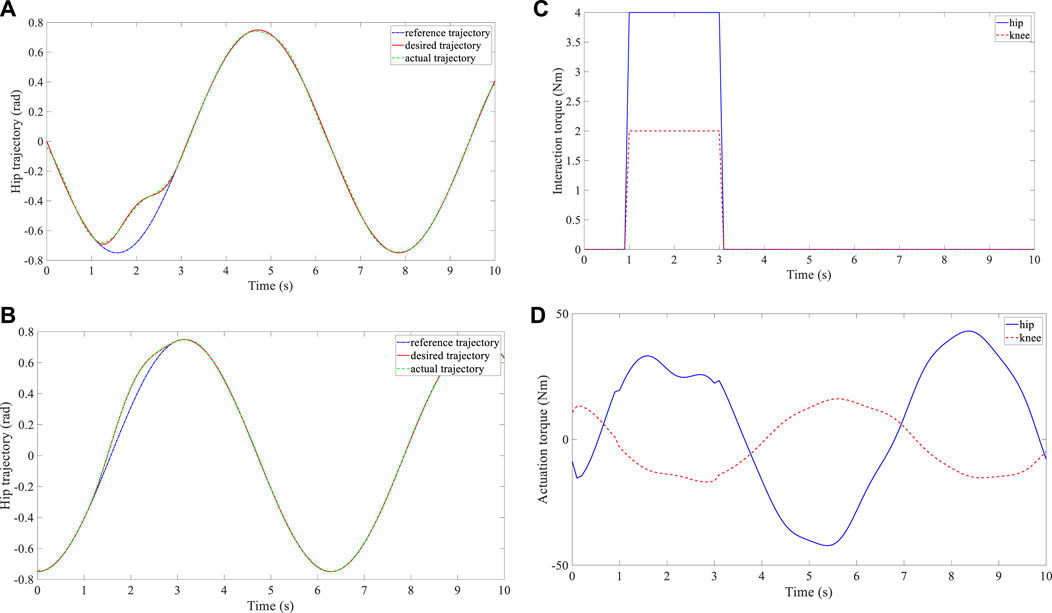
FIGURE 4. Experimental results of subject 1. (A) Trajectory deformation and tracking of the hip joint. (B) Trajectory deformation and tracking of the knee joint. (C) Interaction torque at the hip and knee joints. (D) Actuation torque at the hip and knee joints.
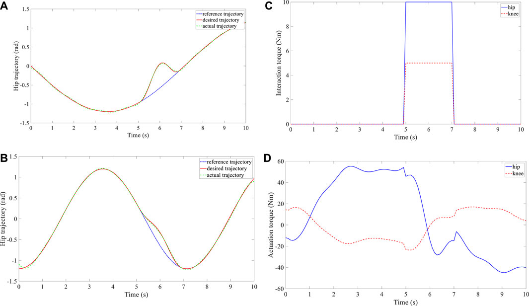
FIGURE 5. Experimental results of subject 2. (A) Trajectory deformation and tracking of the hip joint. (B) Trajectory deformation and tracking of the knee joint. (C) Interaction torque at the hip and knee joints. (D) Actuation torque at the hip and knee joints.
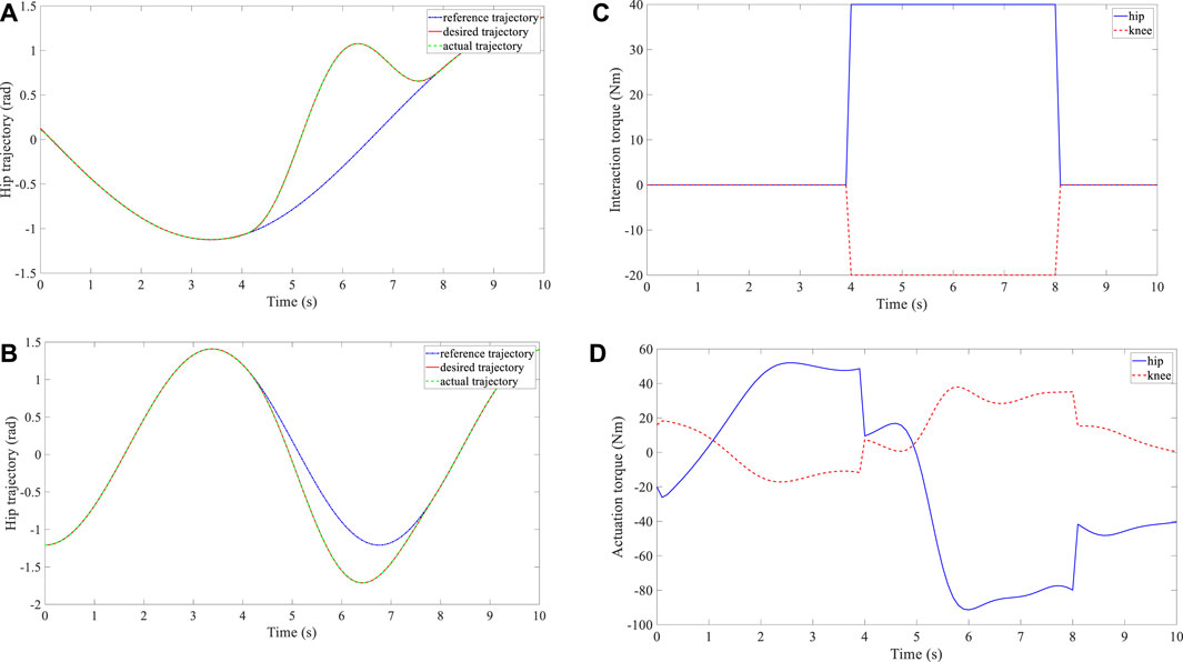
FIGURE 6. Experimental results of subject 3. (A) Trajectory deformation and tracking of the hip joint. (B) Trajectory deformation and tracking of the knee joint. (C) Interaction torque at the hip and knee joints. (D) Actuation torque at the hip and knee joints.
In order to exhibit the control performance more intuitively, quantitative evaluation with three metrics was conducted. In terms of trajectory smoothness, the dimensionless squared jerk (Hogan and Sternad, 2009) was adopted, and its definition is presented in (23). A smaller DSJ value indicates a smoother movement trajectory. As for the compliance assessment, the energy per unit distance (EPUD) (Lee et al., 2018) was selected as (24). When improved compliance was shown, the subject could drive the robot with less interaction torque. A smaller EPUD value indicates higher robot compliance. The root mean square error (RMSE) defined in (25) was utilized to reveal the position error between the desired trajectory and actual trajectory. A smaller value of RMSE indicates better tracking effect. The three metrics are formulated as follows.
In (23), the parameters
Additionally, to better manifest the advantage of the proposed control framework, comparison experiments were performed with an admittance control without trajectory deformation and feedback gain modification algorithms (Li et al., 2017). The admittance control was implemented with the same robot and subject. The admittance parameters were regulated while responding to the subjects’ biological actions. The trajectory deformation and tracking performance of both control systems were evaluated with the abovementioned three metrics. Additionally, in order to evaluate rehabilitation efficacy, muscle activation improvement was normalized and recorded, and the Fugl-Meyer assessment (FMA) was also deployed for clinical evaluation. Higher normalized EMG value and FMA score indicate rehabilitation improvement. Each trial was conducted three times for accuracy, and the mean values of these metrics are recorded in Table 1. The robot motion compliance and movement smoothness of the hip and knee joint trajectories generated by the deformation trajectory algorithm are much better than those with the admittance control. Furthermore, the tracking performance under the feedback gain algorithm proved more satisfactory compared to the admittance control. The enhancement of the muscle strength and clinical assessment scores is evident compared with the performance without the proposed control framework. Overall, the comparison results prove that the control framework can effectively help the patient learn to move in the proper trajectory, and the training becomes more challenging and brings better rehabilitation efficacy.
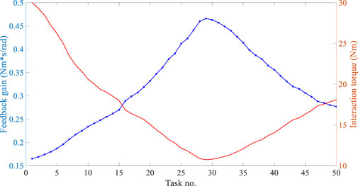
Next, the feedback gain modification algorithm for the AAN controller was experimentally examined during the optimized training task. The subjects were required to voluntarily exert forces on the robot, and the feedback gain
6 Conclusion
In this paper, a control framework is proposed for the simultaneous adaptation of training tasks and robotic assistance for robot-assisted rehabilitation. Specifically, a trajectory deformation algorithm is developed to enable pHRI to regulate the task difficulty in real time, generating a smooth and compliant desired trajectory. Furthermore, an AAN controller, along with a feedback gain modification algorithm, is designed to motivate patients’ active participation, where the robotic assistance is adjusted by evaluating the patients’ performance variance and determining the trajectory tracking error bound. Appropriate training difficulty and assistance level are two important issues in robot-assisted rehabilitation. In this study, the appropriate training difficulty is expressed in the form of making a proper trajectory, which is realized with the proposed trajectory deformation algorithm; and the appropriate assistance level is expressed in the form of increasing the user’s EMG level, which is realized with the proposed AAN controller with the feedback gain modification algorithm. The balance between these two issues is essential for better rehabilitation efficacy, and the proposed control framework can address this balance well. A lower extremity rehabilitation robot with MR actuators is then employed to validate the effectiveness of the proposed control framework. Experimental results demonstrate that the training task difficulty and robotic assistance level can be regulated appropriately according to subjects’ changing motor capabilities.
In future work, more novel methods will be explored to estimate human motor capabilities and improve pHRI control strategies. More diverse training tasks will be involved to meet the rehabilitation requirements of different degrees and types of impairments. Machine learning may be adopted to ensure better time efficiency and greater adaptability of robotic assistance modification. Furthermore, more clinical trials will be carried out to expand the proposed control framework into clinical application.
Data availability statement
The raw data supporting the conclusions of this article will be made available by the authors, without undue reservation.
Ethics statement
All subjects have been informed of the detailed operation procedures and potential risks with signing the consents before participation. The experiments have been approved by the ethics committee of Hefei Institutes of Physical Science, Chinese Academy of Sciences (approval number: IRB-2019-0018).
Author contributions
JX and KH: Methodology, Investigation, Formal Analysis, Writing-original draft. TZ and KC: Data curation, Validation, Writing-review and editing. AJ, LX, and YL: Supervision, Writing-review and editing. All authors contributed to the article and approved the submitted version.
Funding
This research is supported by the National Natural Science Foundation of China (52205018), Natural Science Foundation of Jiangsu Province (BK20220894), State Key Laboratory of Robotics and Systems (HIT) (SKLRS-2023-KF-25), Fundamental Research Funds for the Central Universities (NS2022048), Nanjing Overseas Scholars Science and Technology Innovation Project (YQR22044), Scientific Research Foundation of Nanjing University of Aeronauticsand Astronautics (YAH21004), and Jiangsu Provincial Double Innovation Doctor Program (JSSCBS20220232).
Conflict of interest
The authors declare that the research was conducted in the absence of any commercial or financial relationships that could be construed as a potential conflict of interest.
Publisher’s note
All claims expressed in this article are solely those of the authors and do not necessarily represent those of their affiliated organizations, or those of the publisher, the editors and the reviewers. Any product that may be evaluated in this article, or claim that may be made by its manufacturer, is not guaranteed or endorsed by the publisher.
References
Damsgaard, M., Rasmussen, J., Christensen, S. T., Surma, E., and de Zee, M. (2006). Analysis of musculoskeletal systems in the anybody modeling system. Simul. Model. Pract. Theory 14 (8), 1100–1111. doi:10.1016/j.simpat.2006.09.001
Ferraguti, F., Landi, C. T., Sabattini, L., Bonfè, M., Fantuzzi, C., and Secchi, C. (2019). A variable admittance control strategy for stable physical human-robot interaction. Int. J. Robotics Res. 38 (6), 747–765. doi:10.1177/0278364919840415
Hogan, N., Krebs, H. I., Rohrer, B., Palazzolo, J. J., Dipietro, L., Fasoli, S. E., et al. (2006). Motions or muscles? Some behavioral factors underlying robotic assistance of motor recovery. J. Rehabilitation Res. Dev. 43 (5), 605–618. doi:10.1682/jrrd.2005.06.0103
Hogan, N., and Sternad, D. (2009). Sensitivity of smoothness measures to movement duration, amplitude, and arrests. J. Mot. Behav. 41 (6), 529–534. doi:10.3200/35-09-004-rc
Krebs, H. I., Palazzolo, J. J., Dipietro, L., Ferraro, M., Krol, J., Rannekleiv, K., et al. (2003). Rehabilitation robotics: performance-based progressive robot-assisted therapy. Aut. Robots 15 (1), 7–20. doi:10.1023/a:1024494031121
Lasota, P. A., and Shah, J. A. (2015). Analyzing the effects of human-aware motion planning on close-proximity human-robot collaboration. Hum. Factors 57 (1), 21–33. doi:10.1177/0018720814565188
Lee, K. H., Baek, S. G., Choi, H. R., Moon, H., and Koo, J. C. (2018). Enhanced transparency for physical human-robot interaction using human hand impedance compensation. IEEE/ASME Trans. Mechatronics 23 (6), 2662–2670. doi:10.1109/tmech.2018.2875690
Li, Z., Huang, Z., He, W., and Su, C-Y. (2017). Adaptive impedance control for an upper limb robotic exoskeleton using biological signals. IEEE Trans. Industrial Electron. 64 (2), 1664–1674. doi:10.1109/tie.2016.2538741
Losey, D. P., and O’Malley, M. K. (2018). Trajectory deformations from physical human-robot interaction. IEEE Trans. Robotics 34 (1), 126–138. doi:10.1109/tro.2017.2765335
Luo, R., Sun, S., Zhao, X., Zhang, Y., and Tang, Y. (2018). “Adaptive CPG-based impedance control for assistive lower limb exoskeleton,” in Proceedings of IEEE international conference on robotics and biomimetics, 685–690.
Marchal-Crespo, L., and Reinkensmeyer, D. J. (2009). Review of control strategies for robotic movement training after neurologic injury. J. NeuroEngineering Rehabilitation 6 (1), 20. doi:10.1186/1743-0003-6-20
Pehlivan, A. U., Sergi, F., and O’Malley, M. K. (2015). A subject-adaptive controller for wrist robotic rehabilitation. IEEE/ASME Trans. Mechatronics 20 (3), 1338–1350. doi:10.1109/tmech.2014.2340697
Peña, G. G., Consoni, L. J., dos Santos, W. M., and Siqueira, A. A. G. (2019). Feasibility of an optimal EMG-driven adaptive impedance control applied to an active knee orthosis. Robotics Aut. Syst. 112, 98–108. doi:10.1016/j.robot.2018.11.011
Schaal, S. (2006). “Dynamic movement primitives-A framework for motor control in humans and humanoid robotics,” in Adaptive motion of animals and machines (Tokyo, Japan: Springer), 261–280.
Sharifi, M., Mehr, J. K., Mushahwar, V. K., and Tavakoli, M. (2021). Adaptive CPG-based gait planning with learning-based torque estimation and control for exoskeletons. IEEE Robotics Automation Lett. 6 (4), 8261–8268. doi:10.1109/lra.2021.3105996
Shen, Z., Zhou, J., Gao, J., and Song, R. (2018). “Torque tracking impedance control for a 3DOF lower limb rehabilitation robot,” in Proceedings of IEEE international conference on advanced robotics and mechatronics, 294–299.
Sproewitz, A., Moeckel, R., Maye, J., and Ijspeert, A. J. (2008). Learning to move in modular robots using central pattern generators and online optimization. Int. J. Robotics Res. 27 (3–4), 423–443. doi:10.1177/0278364907088401
Wu, X., Li, Z., Kan, Z., and Gao, H. (2020). Reference trajectory reshaping optimization and control of robotic exoskeletons for human-robot co-manipulation. IEEE Trans. Cybern. 50 (8), 3740–3751. doi:10.1109/tcyb.2019.2933019
Xu, J., Li, Y., Xu, L., Peng, C., Chen, S., Liu, J., et al. (2019). A multi-mode rehabilitation robot with magnetorheological actuators based on human motion intention estimation. IEEE Trans. Neural Syst. Rehabilitation Eng. 27 (10), 2216–2228. doi:10.1109/tnsre.2019.2937000
Xu, J., Xu, L., Cheng, G., Shi, J., Liu, J., Liang, X., et al. (2021). A robotic system with reinforcement learning for lower extremity hemiparesis rehabilitation. Industrial Robot Int. J. robotics Res. Appl. 38 (3), 388–400. doi:10.1108/ir-10-2020-0230
Xu, J., Xu, L., Ji, A., and Cao, K. (2023). Learning robotic motion with mirror therapy framework for hemiparesis rehabilitation. Inf. Process. Manag. 60, 103244. doi:10.1016/j.ipm.2022.103244
Xu, J., Xu, L., Ji, A., Li, Y., and Cao, K. (2020b). A DMP-based motion generation scheme for robotic mirror therapy. IEEE/ASME Trans. Mechatronics, 1–12. doi:10.1109/TMECH.2023.3255218
Xu, J., Xu, L., Li, Y., Cheng, G., Shi, J., Liu, J., et al. (2020a). A multi-channel reinforcement learning framework for robotic mirror therapy. IEEE Robotics Automation Lett. 5 (4), 5385–5392. doi:10.1109/lra.2020.3007408
Yao, S., Zhuang, Y., Li, Z., and Song, R. (2018). Adaptive admittance control for an ankle exoskeleton using an EMG-driven musculoskeletal model. Front. Neurorobotics 12 (16), 16–12. doi:10.3389/fnbot.2018.00016
Yuan, Y., Li, Z., Zhao, T., and Gan, D. (2020). DMP-based motion generation for a walking exoskeleton robot using reinforcement learning. IEEE Trans. Industrial Electron. 67 (5), 3830–3839. doi:10.1109/tie.2019.2916396
Zhou, J., Li, Z., Li, X., Wang, X., and Song, R. (2021). Human-robot cooperation control based on trajectory deformation algorithm for a lower limb rehabilitation robot. IEEE/ASME Trans. Mechatronics 26 (6), 3128–3138. doi:10.1109/tmech.2021.3053562
Zhuang, Y., Yao, S., Ma, C., and Song, R. (2019). Admittance control based on EMG-driven musculoskeletal model improves the human-robot synchronization. IEEE Trans. Industrial Electron. 15 (2), 1211–1218. doi:10.1109/tii.2018.2875729
Appendix
AppendixDetermination of Vector Field Function
As presented in (9), the vector field function
Rule 1: Continuity. Once the human force
Then, the trajectory configuration on the boundary condition can be satisfied, i.e.,
Specifically, the deformed trajectory between
Consequently, the original and deformed desired trajectory within the time interval
Applying this waypoint parameterization, the continuity statement (26) can be rewritten as
The above equation can be further rewritten as
where
Rule 2: Smoothness. Although the reference trajectory
where
Rule 3: Compliance. It is pHRI that initiates the trajectory deformation and decides the deformed trajectory shape; the vector field function
where
The proposed cost function (29) contains two terms: the first term means the work done by the trajectory deformation to the human; and the second term is the squared norm of
In order to ensure the compliance of the deformed trajectory, the cost function (29) should be minimized under the constraint (27) to optimize the value of the field vector function
A Lagrangian function is defined as follows to solve the above optimization problem.
where
Through further computation after (32), the subsequent equation (33) can be obtained to reveal the relationship between the field vector function and the interaction torque. In addition to Lagrange multipliers, the reader can refer to (Wu et al., 2020) to find another solver, i.e., linear variational inequality-based primal-dual neural network.
where
where
The determination of the parameter
where
Therefore, following the rule of continuity, smoothness, and compliance, the ultimate expression of the vector field function is clarified as
where
7.2 Stability Analysis of AAN Controller
Combining the modified robot dynamics (15), error dynamics (16), and AAN controller (17), the following equation can be yielded.
For stability analysis, consider a Lyapunov candidate function as
Then, the time-derivative of the Lyapunov function is
Let us introduce a constant
Hence, if the following inequality is satisfied,
The time-derivative of the Lyapunov function satisfies
Through the stability analysis, the Lyapunov candidate
Keywords: rehabilitation robotics, human-robot interaction, biological signal, trajectory deformation, assist-as-needed control
Citation: Xu J, Huang K, Zhang T, Cao K, Ji A, Xu L and Li Y (2023) A rehabilitation robot control framework with adaptation of training tasks and robotic assistance. Front. Bioeng. Biotechnol. 11:1244550. doi: 10.3389/fbioe.2023.1244550
Received: 22 June 2023; Accepted: 29 August 2023;
Published: 02 October 2023.
Edited by:
Tianzhe Bao, University of Health and Rehabilitation Sciences, ChinaReviewed by:
Guozheng Xu, Nanjing University of Posts and Telecommunications, ChinaDong Hyun Kim, Samsung Research, Republic of Korea
Copyright © 2023 Xu, Huang, Zhang, Cao, Ji, Xu and Li. This is an open-access article distributed under the terms of the Creative Commons Attribution License (CC BY). The use, distribution or reproduction in other forums is permitted, provided the original author(s) and the copyright owner(s) are credited and that the original publication in this journal is cited, in accordance with accepted academic practice. No use, distribution or reproduction is permitted which does not comply with these terms.
*Correspondence: Jiajun Xu, eHVqaWFqdW5AbnVhYS5lZHUuY24=
 Jiajun Xu
 Kaizhen Huang1
 Aihong Ji