 Wenqing Wei
 Tianyuan Zhang2
 Junlin Yang
 Yu Qian
 Yating Dong
- 1School of Health Science and Engineering, University of Shanghai for Science and Technology, Shanghai, China
- 2Spine Surgery Center, Xinhua Hospital, Shanghai Jiao Tong University School of Medicine, Shanghai, China
Objectives: To study the mechanical sensitivity of different intervertebral disc and bone material parameters and ligaments under different force configurations and magnitudes in the scoliosis model.
Methods: The finite element model of a 21-year-old female is built using computed tomography. Local range of motion testing and global bending simulations are performed for the model verification. Subsequently, Five force of different directions and configurations were applied to the finite element model applying the brace pad position. The material parameters of the model were related to different spinal flexibilities and included different material parameters of cortical bone, cancellous bone, nucleus and annulus. The virtual X-ray technique measured Cobb angle, thoracic Lordosis, and lumbar Kyphosis.
Results: The difference in peak displacement is 9.28 mm, 19.99 mm, 27.06 mm, 43.99 mm, and 50.1 mm under five force configurations. The maximum Cobb angle difference due to material parameters are 4.7° and 6.2°, which are converted to thoracic and lumbar in-brace correction difference of 18% and 15.5%. The maximum difference in Kyphosis and Lordosis angle is 4.4° and 5.8°. The average thoracic and lumbar Cobb angle variation difference in intervertebral disc control group is larger than that in bone control group, while the average Kyphosis and Lordosis angle is inverse. The displacement distribution of models with or without ligaments is similar, with a peak displacement difference of 1.3 mm in C5. The peak stress occurred at the junction of the cortical bone and ribs.
Conclusion: Spinal flexibility largely influences the treatment effect of the brace. The intervertebral disc has a greater effect on the Cobb angle, the bone has a greater effect on the Kyphosis and Lordosis angles, and the rotation is affected by both. Patient-specific material is the key to increasing accuracy in the personalized finite element model. This study provides a scientific basis for using controllable brace treatment for scoliosis.
1 Introduction
Scoliosis is a musculoskeletal disorder characterized as a three-dimensional (3D) deformity with a prevalence of 0.47%–5.2% in adolescents, and a higher incidence in females (Konieczny et al., 2013; Wei et al., 2022). Although many potential etiologies of scoliosis have been proposed, including biomechanical, genetic, and neonatological; the primary etiology is unknown (Fadzan and Bettany-Saltikov, 2017). Curve progression deforms the patient’s back, and depending on the severity, may lead to psychological problems, back pain, local motor dysfunction, and cardiovascular disease (Aebi, 2005; Colak et al., 2017). The Scoliosis Research Society (SRS) categorizes AIS treatment into observation, conservative methods, and surgery (Negrini et al., 2015; Kaelin, 2020).
If the curve ranges from 20° to 45°, bracing is the only acknowledged non-surgical treatment that decreases the probability and affects the coronal curvature of scoliosis patients (Karavidas, 2019). In addition to the casting method, the development of computer-aided design and manufacturing (CAD-CAM) and CAD and finite element modeling (CAD-FEM) has increased the number of options for brace manufacture (Bidari et al., 2021). According to previous studies, the Cobb angle is better corrected by CAD-FEM and CAD-CAM methods compared with conventional methods (Weiss and Kleban, 2015). Although the braces designed using CAD-FEM have been put into clinical use, long-term effects have not been comprehensively evaluated. Thus far, only Guy et al. (2021) found clinical outcomes to be similar to or better than previously reported brace-wearing studies in patients treated with CAD-CAM-designed stents (with or without FEM) using a Randomized Controlled Trial (RCT) in 2 years (n = 94 brace-wearing patients). The In-Brace correction (IBC), which partly determines long-term outcome, is related to the experience of the designer. Using FEM to predict IBC not only directly improves the brace treatment, but also allows the clinician to participate in the brace design to further explore the relationship between brace design and long-term outcome.
The SRS generally does not recommend bracing for adult patients with scoliosis. However, some progress has been made in brace treatment for adults. Weiss et al. (2016) published a case report on bracing and exercise treatment for a 37-year-old female patient. In a 16-month follow-up, the Cobb angle of the lumbar Kyphosis improved from 50° to 32°. Papadopoulos (2013) found that in 53% (n = 144 adults) of the patients, the Cobb angle improved from 9% to 23%. Mauroy et al. (2016) showed that 24% (n = 158 adults) of patients with scoliosis improved more than 5° after 5 years of brace treatment. Thus, Non-growth factors of orthosis can be obtained through adult cases.
The finite element method (FEM) is a numerical simulation method that was first used in the treatment of spinal biomechanics in 1972 (Cui et al., 2022). Since the representative comprehensive volumetric models, including the entire spine and rib, are time-consuming in 3D reconstruction and calculation; studies based on representative segmental volumetric models, typically 1 motion segment, are more commonplace in spinal biomechanics (Wang et al., 2014). Because of the structural complexity of scoliosis, segment modeling cannot adapt to the curve change of the whole spine; therefore, comprehensive models are required in brace treatment. Clin et al. (2011) first applied gravitational loads to show the importance of biomechanical brace action in preventing the scoliotic spine from bending under gravitational forces. A comprehensive personalized FEM, including the heart, liver, spleen, and other organs was built by Guan et al. (2020). This provided the scientific basis for designing a new corrective brace for scoliosis treatment. Karimi et al. (2019) applied various force configurations on the spinal curves, which may allow for automated orthotic selection in future studies. The biomechanical behaviour of a scoliotic spine may not be the same and sensitivity analysis is required to improve the accuracy of the finite element model.
The CAD-FEM brace can be designed to be more controllable to achieve a better treatment effect, thus one of the main issue to meet precision medicine is to assess the impact of the patient’s own flexibility. This study is a material sensitivity analysis based on FEM for a scoliosis patient. Due to the different range of spinal flexibility among patients, it is difficult to obtain an accurate prediction of results in conventional finite element analysis. The spinal flexibility in terms of material distribution is related to the material parameters of the bone, disc and ligament of the spine. Therefore, to improve the accuracy of brace treatment, setting different material parameters by FEM suggest a better understanding on the relationship between spinal material flexibility and clinical indicators in brace treatment. This method highlights the importance of patient-specific materials in accurate finite element models and provides a theoretical basis for designing more controllable bracing.
2 Materials and methods
2.1 Establishment of the finite element model for scoliosis
The patient was a 21-year-old female with scoliosis, with a thoracic Cobb angle of 26° and a lumbar Cobb angle of 40° measured by X-ray images. The computed tomography (CT) scanning was approved by the relevant ethics board (Approval No. XHEC-D-2021-150). GE Revolution CT was used to scan the patient (0.625 mm slice thickness) from C1 to the pelvis. Elementary point cloud models of each bone structure were extracted according to the thresholding Hounsfield unit of bone. Here, the separated bone was connected using region growing processes, wrapping, and smoothing in medical image processing software (Mimics 19.0; Materialise, Leuven). Reverse engineering software (Geomagic Wrap 2021; Geomagic, America) converted whole vertebral bodies to a 3D geometric model for the established intervertebral disc and set cortical bone thickness to 0.8 mm. In computer-aided design software (Solidworks 2021; Dassault, America), according to the anatomical structure and location of the upper and lower surfaces of the vertebral body, the intervertebral disc was extracted and split into nuclear and annuals. The mesh was processed using meshing software (Hypermesh21; Altair, America).
The bone structure, which was built by tetrahedron elements, included the cortical and cancellous bone of vertebral bodies, pelvis, rib, sternum, sacrum, and costal cartilage. Ligaments, including the anterior longitudinal ligament, posterior longitudinal ligament, interspinous ligament, supraspinous ligament, ligamentum flavum, and intertransverse ligament, are simulated by spring elements using engineering simulation software (Workbench; Ansys, America). Intervertebral discs were built using hexahedral elements. Grid quality was fixed according to the Hypermesh default “Check item,” and all elements passed the inspection. The establishment process of the finite element model for scoliosis is shown in Figure 1.
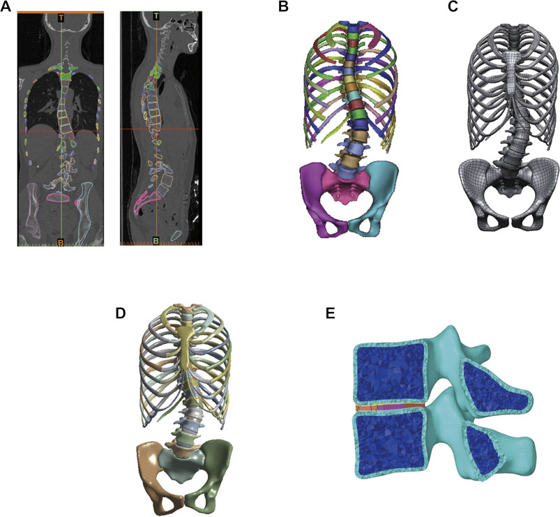
FIGURE 1. Establishment of the finite element model of patient with scoliosis. (A) Constructing the bone structure by using CT data of scoliosis patient. (B) Bone structure model. (C) Bone structure of reverse engineering into the geometric model and soft tissue establishment. (D) Global finite element model of scoliosis. (E) Finite element model of the vertebral segment.
2.2 Mechanical parameter
In this study, each component was regarded as an equilibrium elastic material, while the ligament structure of spinal functional units is stimulated by linear tension springs. The mechanical parameter of solid elements was taken from previously published data (Table 1). Table 2 shows the parameters of each ligament (Goel et al., 1993; Zhang et al., 2022). The flexibility of the intervertebral disc is hypothesized to affect the curve change (Clin et al., 2007), and further concern about osteoporosis is considered in this study. The transition mechanical parameter was calculated using the linear relation for personalized material classification.
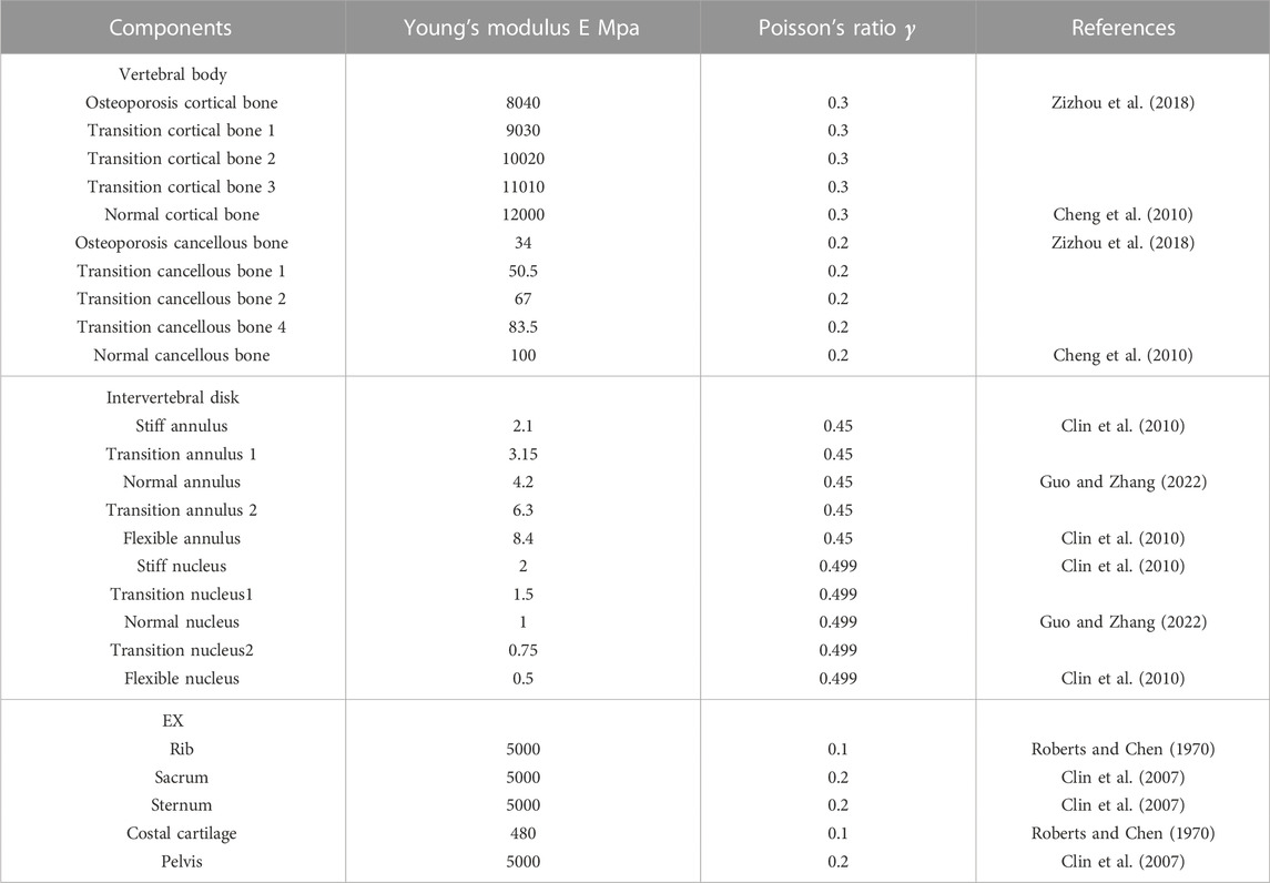
TABLE 1. Material properties of each component.
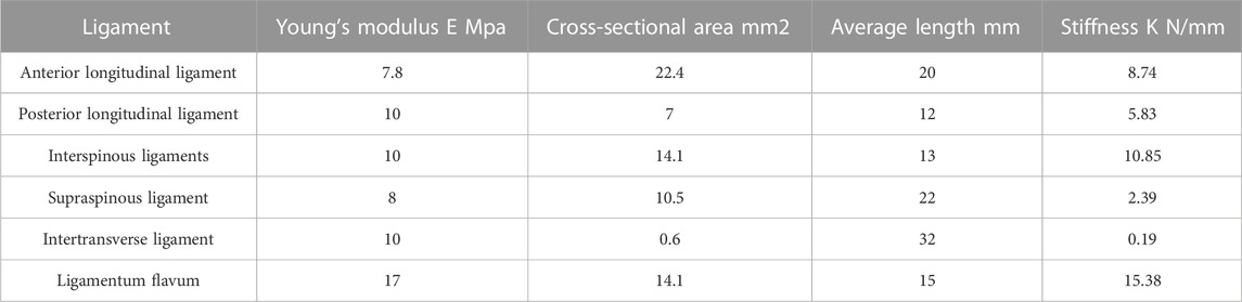
TABLE 2. Material properties of each ligament as spring.
The intervertebral disc control group is composed of normal bone structure, while the bone control group is composed of normal intervertebral disc stiffness. To verify the difference between the most flexible and stiff spine, this study combines osteoporosis vertebral bodies with the most flexible intervertebral disc as, the most flexible spine. The stiffest spine is composed of normal vertebral bodies and stiff intervertebral discs.
2.3 Boundary conditions
Two experiments are used to test model verification, the bending film of the whole spine and the ROM (range of motion) of T1 to T4 are used to verify the biomechanical characteristics of the finite element models. This is done while taking into consideration the patient’s disc stiffness and Hounsfield unit of bone in CT. The Young’s modulus is determined from the density, which can be calculated in Hounsfield units. The Young’s modulus converted to vertebral cortical Hounsfield units is slightly higher than the cortical bone material parameters in the material parameters. For ease of calculation, normal cortical bone parameters are used for cortical bone and normal cancellous bone parameters are used for cancellous bone. However, unlike bone, it is not possible to obtain material parameters for discs using CT. During bending verification, three different mechanical properties of the disc (normal, flexible, and stiff) are considered. According to the distance measured in the bending film, displacement is applied to the T1 top surface, while the sacrum is fixed. Since the ROM of the spine model will change with spinal deformity, further regional segment biomechanical characteristics are approved by measuring the ROM from T1 to T4, which is less affected by scoliosis than other segments. Normal disc mechanical properties are used to established models. Pure moments in flexion/extension, lateral bending, and axial rotation were applied at 4 Nm in T1 top. The bottom of T4 were boned.
This study focuses on the effect of different mechanical parameters on the spinal orthosis. The loading conditions of the finite element model were based on the classical principle of the three-point system in the Cheneau brace. Force F1 was applied to the sixth, seventh and eighth ribs corresponding to the thoracic apex, while force F2 at the lumbar apex was applied to L2 and L3 to simulate the resultant force generated by the pad. Force F3 applied to the second, third and fourth ribs and the boned pelvis is the counterforce applied proximally and distally to F1 and F2 to satisfy the three-point system. Five groups of integrated three-dimensional boundary conditions are analyzed for the overall spinal orthosis, similar to the loading conditions of Karimi et al. (2019) (Table 3). The applied range of force varied between 0 N and 100 N in different direction.
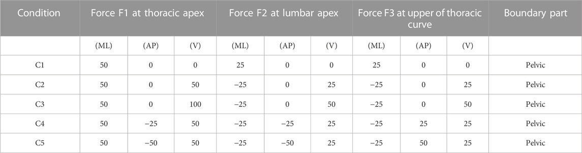
TABLE 3. Various force configurations and magnitudes.
The initial geometry of the patient was acquired by CT in the supine position, and gravity load can transform CT from a supine to a standing position for better understanding (especially at the biomechanical level). Gravitational forces are applied according to the loading method of Clin et al. (2010). All load conditions include applying a virtual gravity load followed by an orthopedic scheme load.
3 Results
For the model validation section, the simulated bending position of the vertebral bodies is shown in Figure 2, and the stiff spine is the closest to the bending film of the three models (Figure 3). Figure 4 shows the ROM of T1 to T4, and the average stiffness are close to the comparison results (Busscher et al., 2010; Xin, 2016; Sheng, 2021). Therefore, the scoliosis models can be used for finite element analysis.
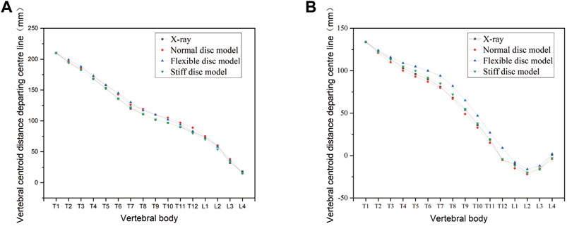
FIGURE 2. Changes in the bending curvature of the simulated spine with different spinal flexibility. (A) Left bending. (B) Right bending.
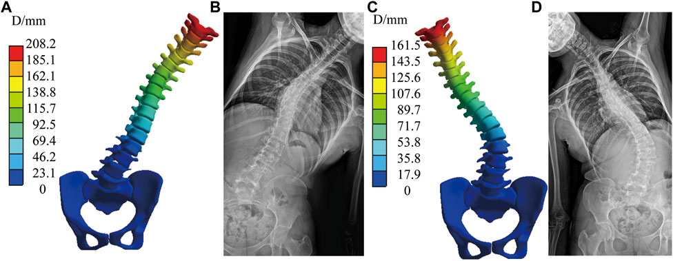
FIGURE 3. Simulated bending position of the stiff spine with bending film of X-ray. (A) Simulated left bending. (B) Left bending of X-ray. (C) Simulated right bending. (D) Right bending of X-ray.
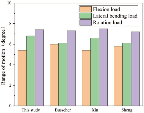
FIGURE 4. Range of motion among T1 to T4.
The spinal index parameters under different force configurations and magnitudes are shown in Tables 4A, B. Cobb angle, thoracic Lordosis, and lumbar Kyphosis were measured after converting the “exporting.stl” file of the result to X-rays using the Virtual X-ray tool in Mimics (Materialise, Leuven), which used to allow engineers to create virtual X-rays of projects to find the optimal angle for 2D/3D registration (Figure 5). Additionally, axial rotation was measured by the Joint function in Workbench.
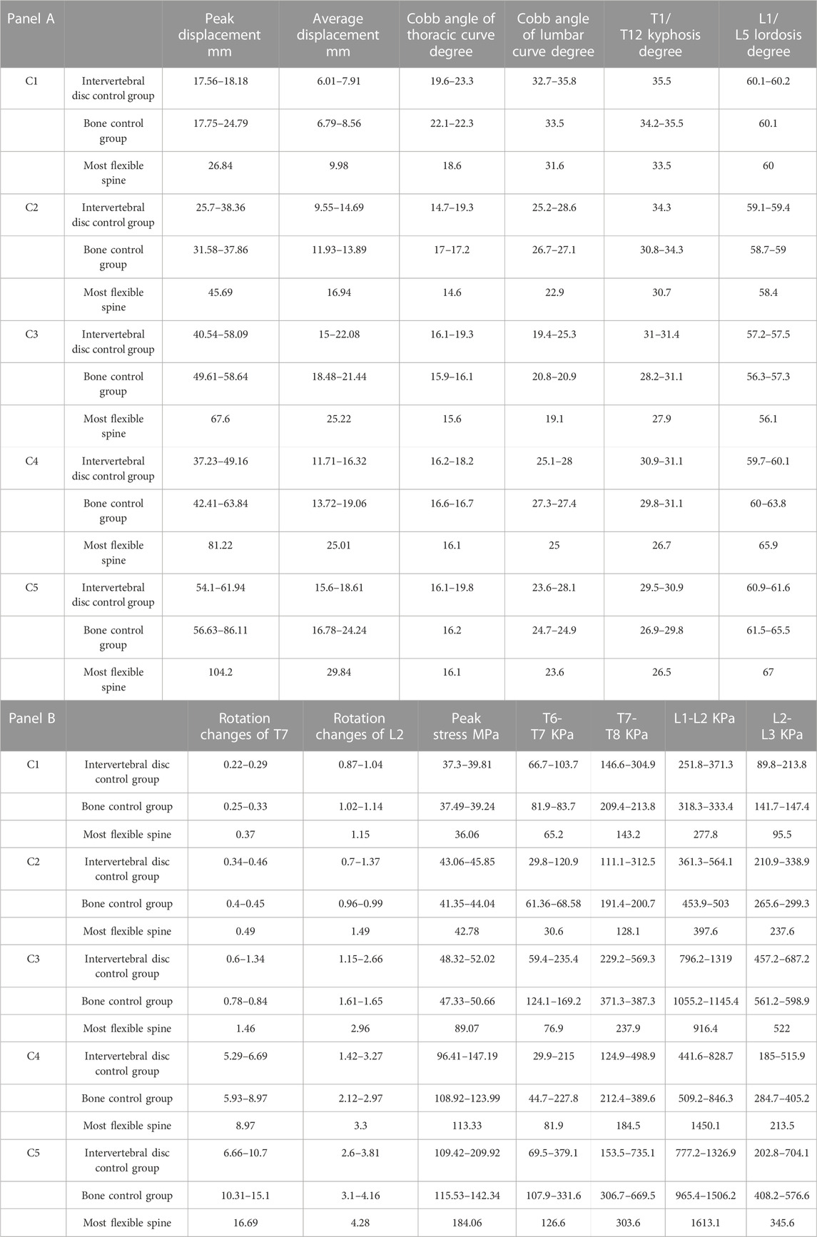
TABLE 4. Spinal parameters under different force configurations and magnitudes.
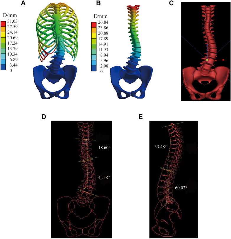
FIGURE 5. Measurement process for virtual X-ray in the most flexible spine in C1. (A) Displacement of the spine model. (B) Displacement of vertebral bodies. (C) Geometry model cast in virtual X-ray. (D) Measurement of the Cobb angle in the coronal plane. (E) Measurement of the Kyphosis and Lordosis angle in the sagittal plane.
Figure 6 shows the displacement distribution of the spine under C1, the effect of different mechanical parameters on the displacement distribution of the spine is not significant, and there is only a certain difference above the displacement peak. This result is applicable to the other four sets of boundary conditions, the common characteristics are shown in the transition mechanical parameter group, only displacement scale difference. The stiffer the material parameter, the lower the peak displacement of the spine. Combined with Table 4, the Cobb angle decreases with an increase of the modulus of the intervertebral disc, and the bone has little influence on the Cobb angle (which varies within 1°). Lordotic and Kyphotic angles are less affected by the intervertebral disc and basically vary within 1° but are more affected by bone, except Lordotic angels of interverbal disc control group under C5 has difference of 1.4°. The Kyphotic angle increases with the increase of the bone modulus. Under C4 and C5, the Lordotic angle increases with the decrease of the bone modulus, while there was no significant difference without sagittal force.
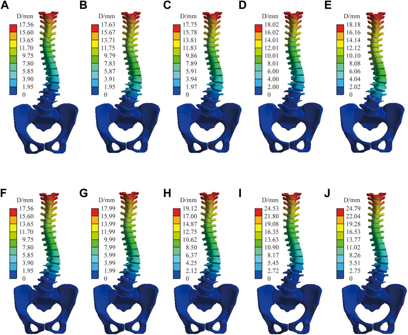
FIGURE 6. Spinal displacement distribution under C1. Bone control group: (A) Stiff intervertebral disk. (B) Transition intervertebral disk 1. (C) Normal intervertebral disk. (D) Transition intervertebral disk 2. (E) Flexible intervertebral disk. Intervertebral disc control group: (F) Osteoporosis vertebral body. (G) Transition vertebral body 1. (H) Transition vertebral body 2. (I) Transition vertebral body 3. (J) Norma vertebral body.
Figure 7 shows the normal spinal coronal virtual X-ray under C2 and C1, the thoracic and lumbar Cobb angle of C1 is significantly lager than C2 while the Lordosis and Kyphosis angle is slightly lager than C2. IBC were shown as a reducutin ratio of Cobb angle with brace. Under all material assembly protocols, The thoracic IBC of C1 ranges from 10.3% to 28.4%, while C2 ranges from 25.8% to 43.5%. The lumbar IBC of C1 and C2 are 10.5%–21.3% and 28.5%–42.8%, respectively. A higher correction indicates that the spine is more likely to be corrected with a brace. C2 with transverse force can effectively reduce the Cobb angle of the thoracic and lumbar curve, Lordosis and Kyphosis angle compared with C1.
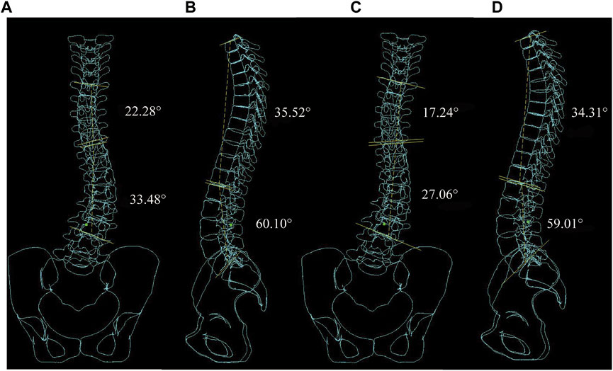
FIGURE 7. Virtual X-ray of normal spinal. (A) Coronal plane Cobb angle measurement in C1. (B) Sagittal plane Kyphosis and Lordosis angle measurement in C1. (C) Coronal plane Cobb angle measurement in C2. (D) Sagittal plane Kyphosis and Lordosis angle measurement in C2.
Figure 8 shows the stiffest spinal displacement distribution under C2 and C4, forces in the sagittal direction has a large effect on the displacement distribution. Combined with the Table 4, the thoracic and lumbar IBC of C4 is 30%–38.1% and 30%–37.5% under all material assembly protocols, respectively. Compared with C2, the increase of sagittal force in C4 will also reduce its Lordosis angle but increase its Kyphosis angle. Negatively impacts the correction of the Cobb angle in some flexible mechanical parameter. Increasing force on the sagittal and transverse planes like C3 and C5 will have a positive influence on the displacement of the spine, but not all the spinal index parameters according to Table 4.
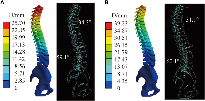
FIGURE 8. The stiffest spinal in C2 and C4. (A) Displacement distribution and virtual X-ray of sagittal plane in C2. (B) Displacement distribution and virtual X-ray of sagittal plane in C4.
The maximum thoracic Cobb angle that varied due to material parameters are 4.7°, 4.7°, 3.7°, 2.1°, and 3.7° respectively under five force configurations, while for lumbar Cobb angle variation material parameters are 4.2°, 5.7°, 6.2°, 3°, and 4.5°. The maximum thoracic and lumbar Cobb angle difference converted to thoracic and lumbar in-brace correction difference is 18% and 15.5%. In intervertebral disc control group, both thoracic and lumbar Cobb angle variation are higher than that in bone control group. The Kyphosis and Lordosis angle variation are inverse to Cobb angle. No obvious pattern is found in the change of peak displacement of between both group. The most flexible group (osteoporosis bone group comebined with flexible disk group) has the largest displacement, rotation changes, while has the smallest thoracic and lumbar angle under all boundary conditions. The Kyphosis and Lordosis angle is minimum under C1, C2, and C3 in most flexible group. While the Lordosis angle become maximum with the inclusion of sagittal plane forces under C4 and C5.
The Workbench Probe function was used to obtain the changes in the axial rotation of the vertebral body. The sagittal force had the greatest effect on rotation compared with the forces in the coronal and axial directions, as is shown in C2 and C4. The axial rotation of the vertebral body has a specific relationship with the intervertebral disc and bone, and the rotation angle decreases with the elastic model of the bone and the intervertebral disc. In the sagittal plane, the correction of rotation degree is most apparent in C4 and C5 under the loading condition, and the change of rotation degree of the thoracic spine is greater than that of the lumbar spine. The most flexible spine axis rotation of the vertebral body is measured at C2, C4, and C5 (Figure 9). Intervertebral disc stiffness has the greatest influence on Cobb angle and decreases with increased intervertebral disc modulus. Bone stiffness has the largest change value in Kyphosis and increases with the increase of bone elastic modulus. The bone and intervertebral disc both significantly influence the axial rotation of the vertebral body.
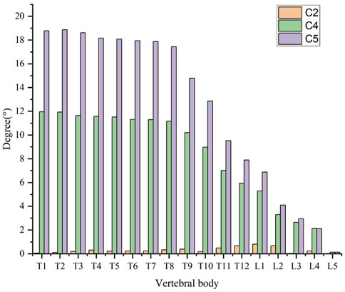
FIGURE 9. The axis rotation of the vertebral body of the most flexible spine in C2, C4, and C5.
Figure 10 shows that the stress distribution under five force configurations in normal spine. The stress of cortical bone was greater than that of cancellous bone. The peak stress occurred at the junction of T6 and sixth rib on the convex side of cruve under C1, C2, and C3. While under C4 and C5, it occurred at the T5 and fifth rib on the concave side of cruve. Stress mainly distribute in the ribs and the posterior border of vertebral body. In addition, a decrease in the elastic modulus of the intervertebral disc leads to an increase in the overall model stress; however, the opposite occurs for the bone (Table 4).
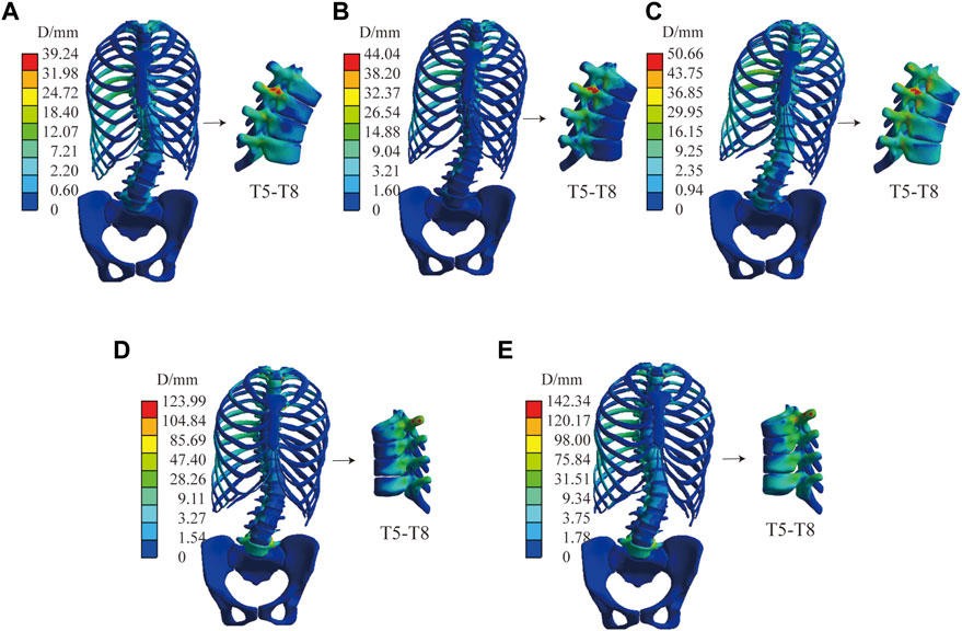
FIGURE 10. The stress distribution of normal spine. (A) Stress distribution in C1. (B) Stress distribution in C2. (C) Stress distribution in C3. (D) Stress distribution in C4. (E) Stress distribution in C5.
This study assessed the intervertebral disc between T6 and T7, T7 and T8, L1 and L2, and L2 and L3. Under the condition that only minor transverse and longitudinal loads are considered, the maximum stress of the stiffness of the intervertebral disc is affected the most, and the peak stress of the most flexible intervertebral disc is at a minimum. Moreover, the elastic modulus of bone has a limited effect on stress. After the orthopedic load in the direction of the Z-axis was increased for C3, the stress peak caused by bone changes had a specific change. When the sagittal plane loading was added to C4 and C5, the stress peak generated by the elastic modulus of bone changed significantly (Table 4).
In addition to the above models, we also compared the displacement comparison between the model without ligaments and those with ligaments using the same material properties. Figure 11 shows, under C5, the displacement distribution of the two models is similar, with a peak displacement difference of 1.3 mm. The rest of the models vary less than the boundary condition under C5.
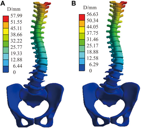
FIGURE 11. The displacement distribution of normal spine under C5. (A) Finite element model with ligaments. (B) Finite element model without ligaments.
4 Discussion
Personalized customization braces for scoliosis are a major topic of interest. Park et al. (2018) designed a robotic spine exoskeleton to treat spine deformity. Dong and Wu (2018) innovated a brace with a magnetic force device to correct scoliosis deformity. They demonstrated a traditional brace, improved with topology optimization, that promised immediate correction. This brace was lighter, thinner, and covered less surface area on trunk. In future, more research will be conducted on the intersection of new technologies for better scoliosis treatment.
Thus, applied force instead of the loading displacement on bone structure in this study can enable better observation of responses to mechanical loading according to different spine stiffness. Few studies based on the FEM mechanical properties sensitivity analysis are used to improve the accuracy of the finite element model. Petit et al. (2004) evaluated spine flexibility as intervertebral disc stiffness. In this study, intervertebral disc stiffness influences a 3D plane, and the bone substance is studied. This study aims to improve the effectiveness of the scoliosis model but also to provide baseline data for simplifying the scoliosis model in the future.
In the same mechanical property analysis, the result confirms the following points. The vertical upward force component can improve the scoliotic curve as was shown in C1 and C2. Increased force does not yield better outcomes in brace treatment. Instead, a sagittal pair-of-force system can effectively correct axial rotation and influence the thoracic more than the lumbar, while sagittal force significantly impacts the Lordosis and Kyphosis angle. These findings are also supported by Karimi et al. (2020) and the Chêneau-type brace design principle (Rigo and Jelacic, 2017). A different view is based on the different stiffness of the components. Both the vertebral body and intervertebral disc influence the displacement of the brace treatment. In this work, the displacement increases with a decrease in modulus. The intervertebral disc mechanical parameter in the coronal plane is much higher compared with the sagittal plane, while vertebral stiffness is the opposite. Clin et al. (2010) found similar results in intervertebral disc stiffness, where the axial rotation of the vertebral body was affected by both stiffnesses.
Changes in material parameters cause scale changes in brace treatment for the same boundary conditions, no structural changes are found in this study. As the overall stiffness of the spine increases, the smaller the deformation of the spine for the same force. In the coronal plane, the Cobb angle is more influenced by changes in the material parameters of the disc and less influenced by the material parameters of the bony structure. In the sagittal plane, the anterior and posterior convex angles are more influenced by the bone. The specific causes are related to the structure of the vertebral segments. In the cross-section, the material parameters of both bone and disc have a significant effect on the axial rotation of the vertebral body. At the same time, the orthopedic effect of the brace is further enhanced when osteoporosis is combined with a lower disc modulus of elasticity. Although the orthopedic effect for some flexible cases in the coronal plane curve is excellent, it should be noted that the sagittal plane spinal curve is also significantly altered, which may cause flat back problems.
For stress distribution, according to the Hueter-Volkmann principle (compressive stresses slow growth, whereas tensile stresses speed up growth), the distribution of the disc vertebral growth plate is a significant indication for Adolescent Idiopathic Scoliosis (AIS) (Kamal and Rouhi, 2020). Because the patient was an adult, this study did not focus too much on the stress distribution of the growth plates. The stress distribution of the intervertebral disc, with changes in mechanical parameters, affects the stress distribution of the intervertebral disc. Thus, in brace design, it is necessary to pay attention to the bending moment balance on the growth plate and mechanical property validation.
The effect of ligaments on scoliosis is negligible; the peak displacement in normal C5 differs by only 1.3 mm (with or without ligaments). In the computer simulation, the primary reason is that the ligament is set as a linear material and is in a state without preloading force. Additionally, during the simulation process, the corresponding surface displacement at both ends of the ligament is small; therefore, the tension between the two points is almost negligible. However, this may be inconsistent with reality. In future studies, we will consider setting a standard length of the ligament and a preloading force based on the standard length difference.
This study has many limitations. The non-linear material parameters (from muscles and ligaments) are not considered. To address this, we will constantly improve our standard finite element model. This model is only effective for the single patient case study. To deal with larger workloads in constructing finite element models (and ethical issues), we will use EOS Imagine and artificial intelligence in future studies. In subsequent studies, more reasonable and detailed boundary conditions to analyze different types of scoliosis as well as brace assembly verification will be considered, and part of the manual angle measurement will be based on a virtual X-ray. In follow-up studies, we will also assess the corresponding automatic measurement software to reduce manual measurement error.
5 Conclusion
This study focused on the different biomechanical properties of spine stiffness and considered the modulus of the patient’s disc and bone as the key to increasing accuracy in the personalized finite element model. In the coronal plane, the Cobb angle is more influenced by changes in the material parameters of the disc and less influenced by the material parameters of the bonal structure. In the sagittal plane, the anterior and posterior convex angles are more influenced by the bone. In the cross-section, the material parameters of both bone and disc have a significant effect on the axial rotation of the vertebral body. Future studies will focus on the biomechanical analysis of many different types of scoliosis patients by FEM, providing the corresponding data and simplification method for the subsequent automatic generation of scoliosis models.
Data availability statement
The original contributions presented in the study are included in the article/supplementary material, further inquiries can be directed to the corresponding author.
Ethics statement
Written informed consent was obtained from the individual(s) for the publication of any potentially identifiable images or data included in this article.
Author contributions
All authors contributed to the research. WW established the FE model and first draft of the paper. TZ is responsible for the angle measurement. YQ and YD performed the calculation. The work was critically revised by JY. All authors commented on previous versions of the paper and read and approved the final version.
Funding
This study was supported by the National Natural Science Foundation of China (Grant Numbers: 82072519).
Conflict of interest
The authors declare that the research was conducted in the absence of any commercial or financial relationships that could be construed as a potential conflict of interest.
Publisher’s note
All claims expressed in this article are solely those of the authors and do not necessarily represent those of their affiliated organizations, or those of the publisher, the editors and the reviewers. Any product that may be evaluated in this article, or claim that may be made by its manufacturer, is not guaranteed or endorsed by the publisher.
References
Aebi, M. (2005). The adult scoliosis. Eur. Spine. J. 14 (10), 925–948. doi:10.1007/s00586-005-1053-9
Bidari, S., Kamyab, M., Ghandhari, H., and Komeili, A. (2021). Efficacy of computer-aided design and manufacturing versus computer-aided design and finite element modeling technologies in brace management of idiopathic scoliosis: A narrative review. Asian. Spine. J. 15 (2), 271–282. doi:10.31616/asj.2019.0263
Busscher, I., van der Veen, A. J., van Dieen, J. H., Kingma, I., Verkerke, G. J., and Veldhuizen, A. G. (2010). In vitro biomechanical characteristics of the spine A comparison between human and porcine spinal segments. Spine 35 (2), E35–E42. doi:10.1097/BRS.0b013e3181b21885
Cheng, F. H., Shih, S. L., Chou, W. K., Liu, C. L., Sung, W. H., and Chen, C. S. (2010). Finite element analysis of the scoliotic spine under different loading conditions. Biomed. Mater. Eng. 20 (5), 251–259. doi:10.3233/BME-2010-0639
Clin, J., Aubin, C. E., and Labelle, H. (2007). Virtual prototyping of a brace design for the correction of scoliotic deformities. Med. Biol. Eng. Comput. 45 (5), 467–473. doi:10.1007/s11517-007-0171-4
Clin, J., Aubin, C. E., Parent, S., and Labelle, H. (2010). A biomechanical study of the Charleston brace for the treatment of scoliosis. Spine 35 (19), 940–947. doi:10.1097/brs.0b013e3181c5b5fa
Clin, J., Aubin, C. E., Parent, S., and Labelle, H. (2011). Biomechanical modeling of brace treatment of scoliosis: Effects of gravitational loads. Med. Biol. Eng. Comput. 49 (7), 743–753. doi:10.1007/s11517-011-0737-z
Colak, T. K., Akgul, T., Colak, I., Dereli, E. E., Chodza, M., and Dikici, F. (2017). Health related quality of life and perception of deformity in patients with adolescent idiopathic scoliosis. J. Back. Musculoskelet. Rehabil. 30 (3), 597–602. doi:10.3233/BMR-160564
Cui, H., Wei, W., Shao, Y., and Du, K. (2022). Finite element analysis of fixation effect for femoral neck fracture under different fixation configurations. Comput. Methods. Biomech. Biomed. Engin. 25 (2), 132–139. doi:10.1080/10255842.2021.1935899
Dong, Y., and Wu, M. (2018). Spinal orthopedic brace, has magnetic force device attached with human body to provide force to adjust side protrusion of spine and/or provide force to adjust spine of back-to-back direction of human body. CN207075947-U. Guangzhou: China National Intellectual Property Administration.
Fadzan, M., and Bettany-Saltikov, J. (2017). Etiological theories of adolescent idiopathic scoliosis: Past and present. Open. Orthop. J. 11, 1466–1489. doi:10.2174/1874325001711011466
Goel, V., Kong, W. K., Han, J. S., Weinstein, J. N., and Gilbertson, L. G. (1993). A combined finite element and optimization investigation of lumbar spine mechanics with and without muscles. Spine 18 (11), 1531–1541. doi:10.1097/00007632-199318110-00019
Guan, T., Zhang, Y., Anwar, A., Zhang, Y., and Wang, L. (2020). Determination of three-dimensional corrective force in adolescent idiopathic scoliosis and biomechanical finite element analysis. Front. Bioeng. Biotechnol. 8 (963), 963–1013. doi:10.3389/fbioe.2020.00963
Guo, L. X., and Zhang, C. (2022). Development and validation of a whole human body finite element model with detailed lumbar spine. World. Neurosurg. 163, e579–e592. doi:10.1016/j.wneu.2022.04.037
Guy, A., Labelle, H., Barchi, S., Audet-Duchesne, E., Cobetto, N., Parent, S., et al. (2021). Braces designed using CAD/CAM combined or not with finite element modeling lead to effective treatment and quality of life after 2 Years: A randomized controlled trial. Spine 46 (1), 9–16. doi:10.1097/BRS.0000000000003705
Kaelin, A. J. (2020). Adolescent idiopathic scoliosis: Indications for bracing and conservative treatments. Ann. Transl. Med. 8 (2), 28. doi:10.21037/atm.2019.09.69
Kamal, Z., and Rouhi, G. (2020). Stress distribution changes in growth plates of a trunk with adolescent idiopathic scoliosis following unilateral muscle paralysis: A hybrid musculoskeletal and finite element model. J. Biomech. 111, 109997. doi:10.1016/j.jbiomech.2020.109997
Karavidas, N. (2019). Bracing in the treatment of adolescent idiopathic scoliosis: Evidence to date. Adolesc. Health. Med. Ther. 10, 153–172. doi:10.2147/AHMT.S190565
Karimi, M., Rabczuk, T., Luthfi, M., Pourabbas, B., and Esrafilian, A. (2019). An evaluation of the efficiency of endpoint control on the correction of scoliotic curve with brace. A case study. Acta. Bioeng. Biomech. 21 (2), 3–10. doi:10.5277/abb-01282-2018-05
Karimi, M. T., Rabczuk, T., and Pourabbas, B. (2020). Evaluation of the efficiency of various force configurations on scoliotic, Lordotic and Kyphotic curves in the subjects with scoliosis. Spine. Deform. 8 (3), 361–367. doi:10.1007/s43390-020-00072-x
Konieczny, M. R., Senyurt, H., and Krauspe, R. (2013). Epidemiology of adolescent idiopathic scoliosis. J. Child. Orthop. 7 (1), 3–9. doi:10.1007/s11832-012-0457-4
Mauroy, J. C., Lecante, C., Barral, F., and Pourret, S. (2016). Prospective study of 158 adult scoliosis treated by a bivalve polyethylene overlapping brace and reviewed at least 5 years after brace fitting. Scoliosis. Spinal. Disord. 1128 (2), 28–34. doi:10.1186/s13013-016-0091-x
Negrini, S., Hresko, T. M., O'Brien, J. P., Price, N., Boards, S., and Committee, S. R. S. N.-O. (2015). Recommendations for research studies on treatment of idiopathic scoliosis: Consensus 2014 between SOSORT and SRS non-operative management committee. Scoliosis 10, 8. doi:10.1186/s13013-014-0025-4
Papadopoulos, D. (2013). Adult scoliosis treatment combining brace and exercises. Scoliosis 8 (S2), O8. doi:10.1186/1748-7161-8-s2-o8
Park, J. H., Stegall, P. R., Roye, D. P., and Agrawal, S. K. (2018). Robotic spine exoskeleton (RoSE): Characterizing the 3-D stiffness of the human torso in the treatment of spine deformity. Ieee. Trans. Neural. Syst. Rehabil. Eng. 26 (5), 1026–1035. doi:10.1109/TNSRE.2018.2821652
Petit, Y., Aubin, C. E., and Labelle, H. (2004). Patient-specific mechanical properties of a flexible multi-body model of the scoliotic spine. Med. Biol. Eng. Comput. 42 (1), 55–60. doi:10.1007/bf02351011
Rigo, M., and Jelacic, M. (2017). Brace technology thematic series: The 3D rigo cheneau-type brace. Scoliosis. Spinal. Disord. 12, 10. doi:10.1186/s13013-017-0114-2
Roberts, S. B., and Chen, P. H. (1970). Elastostatic analysis of the human thoracic skeleton. J. Biomech. 3 (6), 527–545. doi:10.1016/0021-9290(70)90037-0
Sheng, W. (2021). Finite element modeling and analysis of personalized scoliosis. master’s thesis. Shanxi: Taiyuan University of Technology.
Wang, W., Baran, G. R., Betz, R. R., Samdani, A. F., Pahys, J. M., and Cahill, P. J. (2014). The use of finite element models to assist understanding and treatment for scoliosis: A review paper. Spine. Deform. 2 (1), 10–27. doi:10.1016/j.jspd.2013.09.007
Wei, W., Zhang, T., Huang, Z., and Yang, J. (2022). Finite element analysis in brace treatment on adolescent idiopathic scoliosis. Med. Biol. Eng. Comput. 60 (4), 907–920. doi:10.1007/s11517-022-02524-0
Weiss, H. R., and Kleban, A. (2015). Development of CAD/CAM based brace models for the treatment of patients with scoliosis-classification based approach versus finite element modelling. Asian. Spine. J. 9 (5), 661–667. doi:10.4184/asj.2015.9.5.661
Weiss, H. R., Moramarco, K., and Moramarco, M. (2016). Scoliosis bracing and exercise for pain management in adults—A case report. J. Phys. Ther. Sci. 28 (8), 2404–2407. doi:10.1589/jpts.28.2404
Xin, D. (2016). Construction and finite element analysis of Lenke3 adult idiopathic scoliosis on nail guide 3D model of thoracic vertebra. Dissertation thesis. Chongqing: Chongqing Medical University.
Zhang, Q., Zhang, Y., Chon, T. E., Baker, J. S., and Gu, Y. (2022). Analysis of stress and stabilization in adolescent with osteoporotic idiopathic scoliosis: Finite element method. Comput. Method. Biomec. 26 (1), 12–24. doi:10.1080/10255842.2022.2044803
Keywords: scoliosis, finite element analysis, spine, brace, biomechancis
Citation: Wei W, Zhang T, Yang J, Qian Y and Dong Y (2023) Material sensitivity of patient-specific finite element models in the brace treatment of scoliosis. Front. Bioeng. Biotechnol. 11:1111449. doi: 10.3389/fbioe.2023.1111449
Received: 29 November 2022; Accepted: 09 February 2023;
Published: 16 February 2023.
Edited by:
Alessandro Borghi, Durham University, United KingdomReviewed by:
Claudio Capelli, University College London, United KingdomMeifal Rusli, Andalas University, Indonesia
Copyright © 2023 Wei, Zhang, Yang, Qian and Dong. This is an open-access article distributed under the terms of the Creative Commons Attribution License (CC BY). The use, distribution or reproduction in other forums is permitted, provided the original author(s) and the copyright owner(s) are credited and that the original publication in this journal is cited, in accordance with accepted academic practice. No use, distribution or reproduction is permitted which does not comply with these terms.
*Correspondence: Junlin Yang, eWp1bmxpbkAxMjYuY29t