 Shuzhang Liang1†
 Jiayu Sun1†
 Chaonan Zhang1
 Zixi Zhu1
 Yuguo Dai1
 Chunyuan Gan1Jun Cai1Huawei Chen1,2*
 Lin Feng1,2*
- 1School of Mechanical Engineering and Automation, Beihang University, Beijing, China
- 2Beijing Advanced Innovation Center for Biomedical Engineering, Beihang University, Beijing, China
Micro-spiral has a wide range of applications in smart materials, such as drug delivery, deformable materials, and micro-scale electronic devices by utilizing the manipulation of electric fields, magnetic fields, and flow fields. However, it is incredibly challenging to achieve a massively parallel manipulation of the micro-spiral to form a particular microstructure in these conventional methods. Here, a simple method is reported for assembling micro-spirals into various microstructures via optoelectronic tweezers (OETs), which can accurately manipulate the micro-/bio-particles by projecting light patterns. The manipulation force of micro-spiral is analyzed and simulated first by the finite element simulation. When the micro-spiral lies at the bottom of the microfluidic chip, it can be translated or rotated toward the target position by applying control forces simultaneously at multiple locations on the long axis of the micro-spiral. Through the OET manipulation, the length of the micro-spiral chain can reach 806.45 μm. Moreover, the different parallel manipulation modes are achieved by utilizing multiple light spots. The results show that the micro-spirulina can be manipulated by a real-time local light pattern and be flexibly assembled into design microstructures by OETs, such as a T-shape circuit, link lever, and micro-coil pairs of devices. This assembly method using OETs has promising potential in fabricating innovative materials and microdevices for practical engineering applications.
Introduction
The spiral structure is typical, such as the DNA double helix (Hu, 2021). It has distinctive properties and advantages over the conventional spherical, rod, or lamellar particles (Dong et al., 2022). Therefore, the spiral structure had a wide range of applications in various fields in recent years (Berny et al., 2020; Chandler et al., 2020; Wu et al., 2021). For example, the spiral structure can be propelled by rotating itself around the long axis. Thus, it is an excellent propulsion method in low-Reynolds number fluids. Micro-spirals are used as magnetic microrobots to achieve targeted drug delivery (Yan et al., 2015; Yan et al., 2017). The propelled velocity of the micro-spiral in fluids by a rotating magnetic field (Tottori et al., 2012) can reach 320 μm/s. Second, the spiral structure itself can exhibit superelasticity like a spring (Li et al., 2017). A stretchable supercapacitor (Shang et al., 2015), fabricated by a carbon nanotube double helix winding structure, can work under 150% stretching conditions. A stretching cycle of a flexible strain sensor with a micro-spiral can reach 5000 cycles (Li et al., 2017). Finally, the spiral structure can also induce a magnetic field by passing current or coupling with electromagnetic waves (Kamata et al., 2011; Cai et al., 2012). An electromagnetic material is fabricated by mixing metallic copper micro-spiral with paraffin (Kamata et al., 2014). The chiral characteristics and high-frequency response properties of the material in the 0.5–3 THz band are demonstrated. In particular, the materials fabricated by array micro-spirals can substantially improve mechanical enhancement, functional anisotropy, and biological tissue engineering (Gansel et al., 2009; Esposito et al., 2015).
To fabricate the materials or devices mentioned previously, micro-spirals are generally manipulated or assembled by applying external fields, such as electric, magnetic, or flow fields. For example, the DNA double helix (He et al., 2011) was conducted by using gate modulation of the surface charge of nanopore walls in an electric field. The electric field could significantly reduce the translocation velocity of DNA at a rate of 55 μm/s per 1 mV/nm. Multiple bio-template metallic helices (Li et al., 2016) were arranged into conductive micro-coil wires by alternating electric fields. Electromagnetically responsive THz structures (Kamata et al., 2014) were prepared by using micro-helix-based metal micro-spiral. Arrayed micro-helix terahertz metamaterials (Li et al., 2019) were designed by magnetron control so that materials with vertical helices exhibited significant chirality, while materials with horizontal helices exhibited about 20% polarization transition. The preparation of large-area arrays of micro-helices (Li et al., 2019) is achieved using a combination of flow and electric fields, reaching ∼70% of the particles assembled into chain-like structures for an area of 100 mm × 20 mm. These methods are used either to manipulate a single particle or to achieve the movement or arrangement of multiple particles together. Although these fields can manipulate and array micro-spiral, it is challenging to achieve the parallel independent manipulation of many micro-spiral particles. Thus, it is difficult to assemble the micro-spiral into various structures in the same microfluidic chip. Significantly, the conventional electric field or fluid field requires the preparation of specific electrodes or structures in the chip, which is costly and fixed.
Optoelectronic tweezers, different from conventional non-contact micro-/nanomanipulation technology [e.g., magnetic control (Lin et al., 2016; Dai et al., 2021), ultrasonic manipulation (Zhang W. et al., 2021), dielectrophoresis (Collet et al., 2015), and optical tweezers (Cheah et al., 2014)], utilize visual patterns to form virtual optical electrodes in a photoelectric layer. Then, it can generate a non-uniform electric field to achieve parallel independent manipulation of particles (Chiou et al., 2005), and adjusting the visual patterns can flexibly manipulate a large number of micro-/nano-objects (Liang et al., 2020; Puerto et al., 2020; Chu et al., 2021), such as cells (Yang et al., 2010; Chu et al., 2020), microorganisms (Mishra et al., 2016), and gold nanoparticles (Jamshidi et al., 2009). In addition, OETs can generate a primarily driven force with a low light intensity compared to optical tweezers by using light-induced dielectrophoresis. For example, 15,000 light spots were used to trap microparticles on a 1.3-mm2 × 1.0-mm2 chip at a projected light power of only 10 nW/μm by the OET system (Chiou et al., 2005). It also achieves patterned graphene devices (Lim et al., 2018), fabricated microelectrode (Meng et al., 2017), and arrayed rod-shaped particles (Iris et al., 2018). The movement velocity and rotational angular speed of microrobots (Zhang et al., 2019) can reach 1.1 mm/s and 9.7 rad/s, respectively, in the OET system. The manipulation force of the microsphere can reach 4.2 nN (Zhang et al., 2016). By parallel independent manipulation of the OET system, the micro-gear structure was assembled (Zhang S. et al., 2021). However, there are only a few reports of DNA manipulation in the OET system (Lin et al., 2009). Moreover, it seems that the micro-spiral structure was seen as a whole body, and the mechanism of the spiral structure was not clearly explained in the reference. In our previous work (Liang et al., 2021a; Liang et al., 2021b), the manipulation of particles with different dimensional shapes was achieved by OETs, and the size range of a single particle is from 2 to 150 μm. We first utilize the OETs to manipulate such a large-size micro-spiral structure.
Here, this study proposed massively parallel manipulation and flexible assembly of complex shape micro-spiral using optoelectronic tweezers, as shown in Figure 1. We first analyzed and simulated the micro-spiral dielectric properties for manipulation by the infinitesimal method. Based on these properties, the multiple light patterns are designed to achieve the joint manipulation of micro-spirulina. Subsequently, the micro-spirulina is parallely manipulated by different light spot modes. Finally, we applied the OETs to achieve a flexible assembly of micro-spirulina of different design microstructures: T-shaped circuits, Z-shaped linkages, and quadrangle-shaped micro-coil pairs. In the future, the present method is expected to be applied in the fabrication of innovative materials or microdevices.
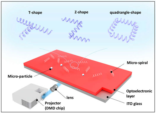
FIGURE 1. Conceptual overview of flexible assembly of micro-spirals via OETs.
Materials and Methods
Micro-Spiral Manipulation Theory
In the OET system, the main manipulation principle is based on the dielectrophoresis (DEP) theory (Hwang et al., 2008). When a dielectric particle is placed in the electric field, it will be polarized. Then, the particle will suffer a DEP force. If the electric field is non-uniform, the net force is not equal to zero. The particle will be attracted or repelled from the high-strength area of a non-uniform electric field. Generally, the spherical bioparticle is analyzed using the model called the multishell model, which can be can be equivalent to a single-shell model (Gagnon 2011; Jubery et al., 2014; Qian et al., 2014), as shown in Supplementary Figure S1. Here, we built an equivalent single-shell spiral model for demonstrating the moving characteristics. In addition, because the spiral can be divided into many cylinders segments (Dalir et al., 2009; Tao et al., 2015; Li et al., 2016), the depolarizing factor of three different axes is set to the same in any one cylinder segment for simplifying the calculation. Thus, the dielectric property parameters use the simplified sphere assumption model to analyze (For details, see Supplementary Theory). The direction force depended on the real part of the Clausius-Mossotti (CM) factor-
where σp and εp represent the electric conductivity and the permittivities of particles, respectively; σm and εm represent the electric conductivity and the permittivities of the medium, respectively; and ω is the angular frequency of the alternating (AC) source.
The real part of the CM factor mainly depends on the dielectric properties of particles, the suspending medium, and input frequency. If
The sphere or rod particles generally use the equivalent dipole moment method to analyze the force (Tao et al., 2015). However, it is not easy to precisely calculate the force of the complex shape of micro-spiral particles. Here, the Maxwell stress tensor (MST) method (Rosales and Lim, 2005), a calculation model by integrating the stress tensor on the particle’s surface, is used to analyze the DEP force. The DEP force can be expressed as (Rosales and Lim, 2005):
where T represents the MST on the particle surface, n represents the unit vector normal to the particle surface,
a-Si:H-Based Microfluidic Chip and Optoelectronic Tweezer System
In this study, the OET system utilizes the a-Si:H-based microfluidic chip to manipulate. The chip is shown in Figure 2A. It is a sandwich structure. The top electrode is indium tin oxide [ITO (NOZO Co., China)] glass (the size is 20 mm × 20 mm). The bottom electrode is ITO glass coated with a-Si:H film (the thickness is 1 μm and the size is 20 mm × 20 mm). The a-Si:H film is fabricated by a plasma-enhanced chemical vapor deposition (PECVD) system. These two electrodes are adhesive by a double-sided tape to form the meddle space (the thickness is 150 μm). The medium and sample can be injected into the area by a side inlet. The schematic of the OET system is shown in Figure 2B, and the image of the whole experiment system is given in Supplementary Figure S2. It consists of three parts. First, the image projected part is composed of a digital micromirror device (DMD) projector (Vivitek H1085, China), a filter, two reflecting mirrors (M), a lens, a dichroic mirror (DM), and an objective lens. The real-time light pattern can be projected onto the microfluidic chip for manipulation through the projected path. Second, the illuminated part comprises an LED, a focusing lens, a mirror (M), a dichroic mirror (DM), and an objective lens. The light generated from the LED can illuminate the microfluidic chip by the illuminated path. Third, the experimental observation part is a microscope (OLYMPUS SZX16, Japan), installed a charge-coupled device (CCD) camera (GS3-U3-23S6C-C; Canada). Through the CCD camera, the experimental processing can be observed in real time. In addition, an input electric field is generated by a function generator source. The light pattern is designed by using a computer. The computer is also used to receive practical information and achieve closed-loop control of the OET system.
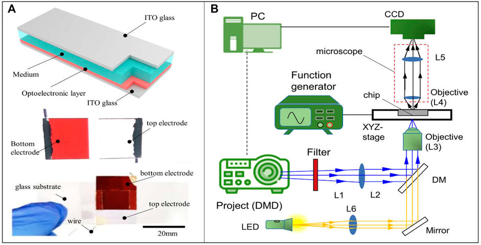
FIGURE 2. Simple schematic diagram of (A) the chip and (B) the OET.
Preparation of the Micro-Spiral Sample
To demonstrate the manipulation of a micro-spiral using OETs, the micro-spirulina, a spiral-shaped aquatic plant, is selected as a sample. The size of micro-spirulina is listed as follows (Cai et al., 2019): length from 52 to 360 μm, helical thread diameter about 5–8 μm, helical thread diameter about 25–36 μm, and helical pitch about 43–57 μm. The micro-spirulina is filtered from the culture medium using a strainer. Then, 5 g micro-spirulina is put into the 50 ml deionized (DI) water as a manipulation sample medium. In addition, 10 μl of the micro-spirulina medium and 10 μl of 20-μm-diameter polystyrene microbeads (Zhongkeleiming; China) solution (50 mg/ml) are mixed in 1 ml of DI water. In the experiment of manipulation and assembly, 10 μl of micro-spirulina medium or the mixed solution is injected into the microfluidic chip of OETs using a pipette.
Results and Discussion
Simulation Parameter Analysis
As previously mentioned, the direction of manipulation force is first required to be considered in OETs, which decides the shape of the light pattern of manipulation. Equation 1 is used to analyze the direction of force according to medium and micro-object electric properties. However, there are a few reports about the electric properties of the original micro-spirulina. Here, the relationship between the direction of manipulation force and electric parameters of micro-spirulina is analyzed by MATLAB, as shown in Figures 3A–C. For the sample, the permittivity and conductivity of DI water are set at 80 and 1.5 × 10⁻³ S/m, respectively (Zhang et al., 2019). The frequency is set as 100 kHz, based on a previous experiment (Liang et al., 2021a). The results show that the value of permittivity and conductivity will be different. Furthermore, according to the permittivity of most biology mediums (Arai et al., 2010; Yang et al., 2010), we set the permittivity of micro-spirulina as 58.52 and then acquired the influence of conductivity to force direction, as shown in Figure 3C. With the mentioned condition, the threshold of direction is 0.0016 S/m. The conductivity of micro-spirulina is approximately measured as 0.04 S/m. Because this value is larger than the threshold value, the micro-spirulina suffers from a positive DEP force, which means it will be attracted by the optical pattern in the OET system.
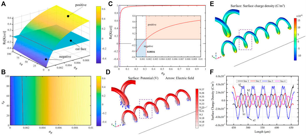
FIGURE 3. Simulation parameters of micro-spirulina analysis. (A,B) Relationship of the real part of CM factor-
There is some research about using MST methods to evaluate the DEP force and interaction force (Rosales and Lim, 2005; Ai and Qian, 2010). It is because the calculation accuracy of the MST method is higher than other methods for complex structure micro-objects (Rosales and Lim, 2005). In this study, the MST method is used to analyze the force of micro-spiral in the OET system. With these parameter conditions, we simulated the electric properties of micro-spirulina in OETs using the AC/DC and fluid–structure interaction module of COMSOL software, as shown in Figures 3D–F. The micro-spirulina usually lay on the bottom electrode, which presented the radius direction parallel to the electric field direction. Thus, the model is set as shown in Supplementary Figures S3A–C. The thickness of the a-Si:H layer is formed as 1 μm, and the dark conductivity and permittivity are set as 1 × 10⁻⁶ S/m and 11.7, respectively (Zhang et al., 2019). The thickness of the medium layer is formed as 150 μm. The sizes of micro-spiral are set as 30 μm in diameter, 6 μm in wire diameter, 35 μm in helical pitch, and 210 μm in the whole length. The distance between the micro-spiral and bottom electrode is 1 μm. The simulation results show that the side near the bottom electrode generates more surface charge than a further side. Four contour lines on the micro-spiral surface are selected to calculate the electric properties to analyze the polarized charge better, as shown in Supplementary Figure S3D. The micro-spiral accumulates more charge on the outside than inside. Because the electric field is uniform without a light pattern projected at this moment, the distribution of electric properties of micro-spiral is periodic along the axis direction, as shown in Figure 3F and Supplementary Figures S3E,F.
However, due to the micro-spirulina being closer to the bottom electrode, the strength of polarization of the bottom part of the micro-spirulina is larger than the top part (Pohl, 1978; Chu et al., 2021), as shown in Figure 3F. Supplementary Figure S3F shows the Maxwell stress tensor distribution. Thus, the net force is not equal to zero, and the micro-spirulina is attracted to the near electrode as a positive DEP effect. In addition, we also analyzed the polarization effect with the differently orientated micro-spiral models (the angle between the long axis of the spiral and bottom electrode are 45° and 90°, respectively), as shown in Supplementary Figure S4. When the micro-spiral is vertical, the polarized surface charge effect can be divided into the same segments because the electric field generates the same gradient difference in each segment. For other orientations, the polarized surface charge density forms a periodic vibration, which agrees with the spiral period.
Demonstrate Multiple Light Patterns to Parallel Move and Rotate the Micro-Spiral
Based on the positive DEP effect of micro-spirulina in the OET system, the light spots are designed to manipulate the complex shape. First, we utilized multiple light areas to collaboratively transport the different length micro-spirulina chains, which are made up of a different number of micro-spirulina, as shown in Figures 4A,B (a video clip is provided as a Supplementary Video S1). The input voltage and frequency are 10 Vpp and 100 kHz, respectively. The results show that the micro-spirulina was assembled into a chain, and the length can reach 806.45 μm. Moreover, the most length chain can be transported to the target position in the microfluidic chip with a velocity of 4.57 μm/s, as shown in Figure 5A. It also shows that the transportation velocity will decrease when the length is beyond a threshold even though the number of light spots increases simultaneously. This could be because the resistance forces have increased, and the gravity could not be ignored with the length of chains increase (Jubery et al., 2014). According to the Stokes law at low Reynolds number in OET system (Zhang 2016; Zhang et al., 2019), the manipulation force is calculated as 1.16pN (detail see Supplementary Theory). Furthermore, to probe the effect of manipulation of multiple light spots for the experimental results, simulations were also carried out in COMSOL Multiphysics. The simulation model is shown in Supplementary Figure S5A. Three light spots illuminate the optoelectric material, and the conductivity is 5 × 10⁻³ S/m. The diameter of light holes is 20 μm. The light spots induce a potential strength area and generate a non-uniform electric field, as shown in Figure 4C and Supplementary Figures S5B–D. Therefore, the micro-spirulina in these areas polarized more charge density, as shown in Supplementary Figure S5E. The electric field generates a positive force, as shown in Supplementary Figure S5F. An analysis of the manipulated force of micro-spiral in an OET is shown in Figure 5B. The micro-spiral is subject to dielectrophoresis force (Fdep), resistance force (Fr), gravity force (Fg), and buoyant force (Fb). These forces trapped the micro-spirulina—the simulation results agree with the manipulation effect in the OET system (see Supplementary Figure S6). When the light pattern moves, the direction of the force will change. The micro-spiral can move with the light pattern. This means utilizing multiple light spots to achieve cooperative manipulation of micro-spiral in a microfluidic chip compared with the three mentioned methods (electric, magnetic, or flow fields).
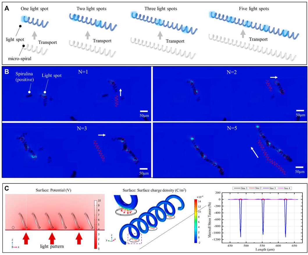
FIGURE 4. Multiple light spots to collaboratively transport the different length micro-spirulina. (A) Schematic of manipulation and (B) experimental results (the number of light spots is 1, 2, 3, and 5, respectively). (C) Simulations of electric potential, surface charge density, and Maxwell stress tensor.
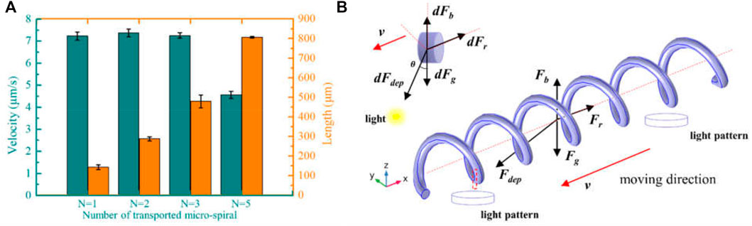
FIGURE 5. (A) Manipulation velocity of the different length of micro-spirulina. (B) An analysis of the manipulated force of micro-spiral in an OET.
In addition, the micro-spirulina was parallel manipulated by multiple light spots in the OET system. We designed the different manipulation modes. It shows that numerous micro-spirulina can be translated in the same direction or opposite direction, as shown in Figures 6A,B. The translation speed can reach 17.86 μm/s. In addition, two different rotation modes were carried out in the OET. One is two micro-spirulina rotating along with a point in the bottom electrode, as shown in Figure 6C. The other is the micro-spirulina spinning along with an end of itself, as shown in Figure 6D (a video clip is provided as a Supplementary Videos S2, S3). The linear speed of rotation can reach 21.13 μm/s. The manipulated force can reach 3.58 pN. As shown in Figure 7A, different manipulation modes may induce a sligthly influence on the manipulated velocity of micro-spiral. It mainly depends on particles, input source, and light pattern (Jubery et al., 2014; Liang et al., 2020) in the OET system. For the rotation along with a point of the micro-spiral, the velocity is smaller than other ways due to the cross-sectional area in the moving direction being larger than different ways. These manipulation modes indicate that the complex shape of micro-spiral could be flexibly manipulated using multiple light patterns in OETs.
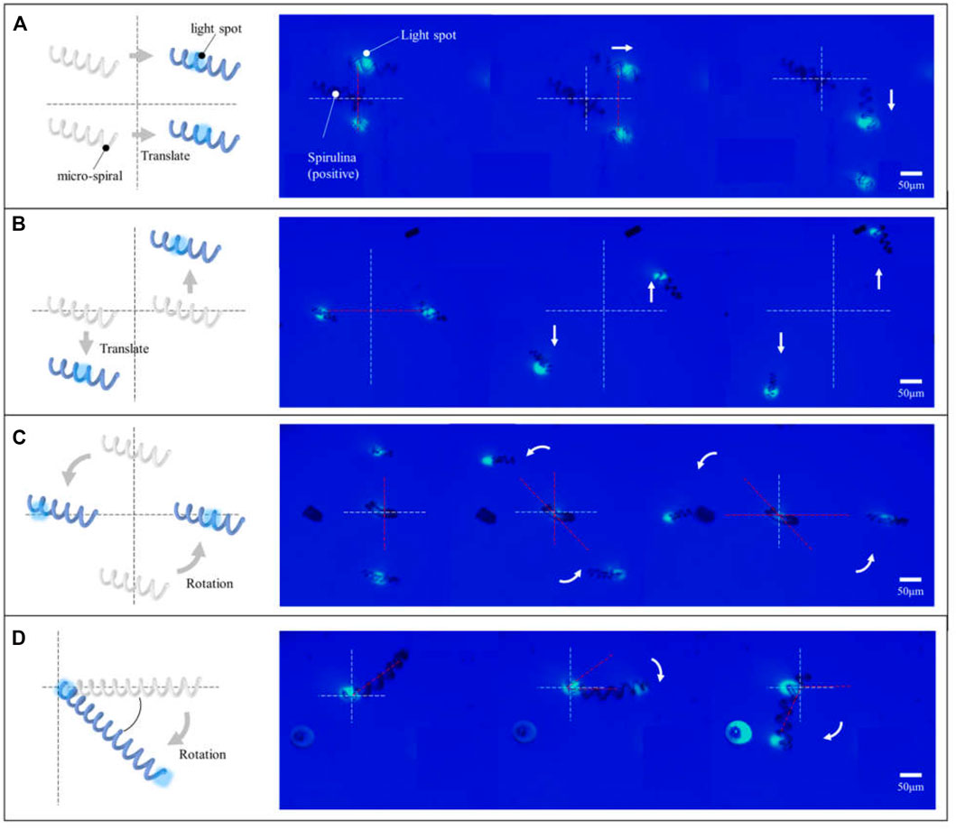
FIGURE 6. Micro-spirulina were parallely manipulated by multiple light spots in the OET system. Translated in the (A) same direction and (B) opposite direction. Rotating along with (C) a point in the bottom electrode and (D) a point of itself.
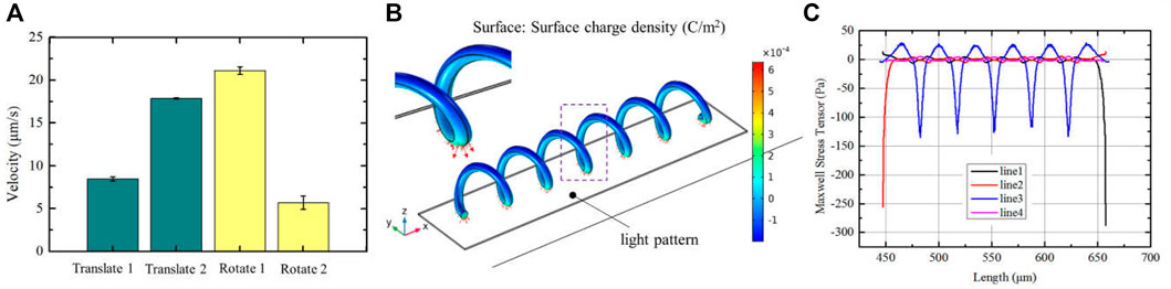
FIGURE 7. (A) Manipulation velocity of the different manipulation modes; simulation results of (B) surface charge density and (C) Maxwell stress tensor distribution when the light pattern with a little bit bigger than the length of micro-spiral.
On the other hand, we also analyzed the electric effect when the light spot is larger than the length of the structure (Zhang et al., 2022) (see Supplement Figure S7). The results of polarized surface charge and Maxwell stress tensor are shown in Figures 7B,C, respectively. In this condition, the polarized surface charge density forms a periodic variation, which agrees with the spiral period. The micro-spiral is confined within the optical pattern and moves with the light pattern together. These could affect the flexibility of manipulation. But, it can be applied to improve the stability in the transportation process.
Flexibly Assemble Micro-Spiral Into Different Microstructures
To test the convenient control complex shape of micro-spiral with the aforementioned manipulation effect, we applied the OETs to assemble the micro-spirulina. As shown in Figure 8, the micro-spiral can be flexibly made as different shapes such as T-shape, Z-shape, and quadrangle shape (a video clip is provided as Supplementary Videos S4). Even though polystyrene particles adhered to the surface of micro-spirulina (Jones 1986; Liang et al., 2021a), they could also achieve assembly. This means that the assembly of micro-spiral could treat with special structure requirements and corporately assemble with other shape micro-objects (Zhang S. et al., 2021). Compared with the traditional assemble method (Fragouli et al., 2014; Li et al., 2016), this is easy to manipulate the micro-spirulina to form more specific shapes in one application device. Furthermore, utilizing the capacity of selecting OETs (Zhang et al., 2018; Puerto et al., 2020), the specific size design of assembly of micro-spirulina could sort from more samples improving the efficiency. In the future, we propose that the flexible assembly of the complex shape of micro-spiral by the OET system may be appropriate for assembling the complex vessel model structure. In addition, the automotive microassembly is also promising by programming a light pattern moving in the OET system (Liang et al., 2021b; Cao et al., 2021). We are confident that the reported method coupling with other methods would have many applications.
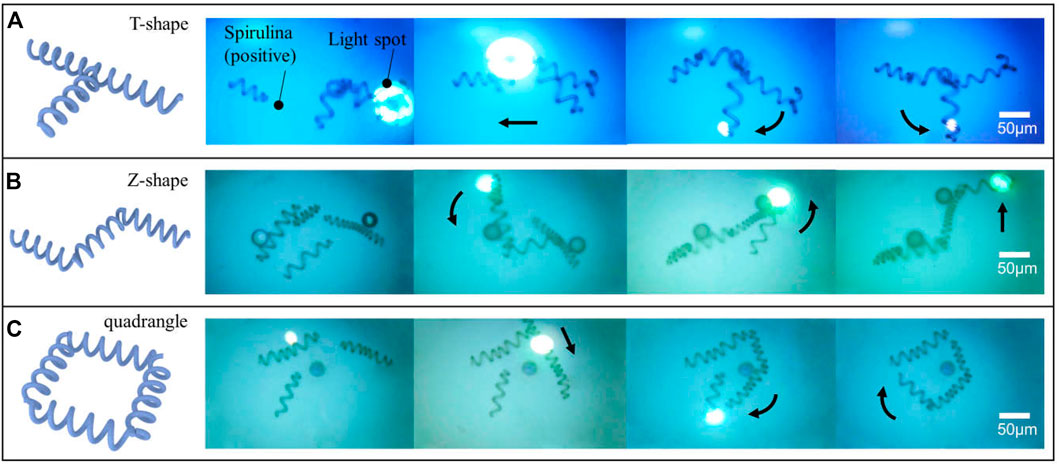
FIGURE 8. Flexible assembling micro-spiral into the different shapes of microstructure: (A) T-shape, (B) Z-shape, and (C) quadrangle shape.
Conclusion
This study aimed to achieve a flexible assembly of the complex shape of micro-spiral using the OET system. First, the direction of the manipulation force was analyzed. By using condition, the threshold value was 0.0016 S/m. Combined with the simulation result, the micro-spirulina was attracted by the optical pattern in the OET system. Utilizing the positive DEP effect, multiple light spots were applied to manipulate the micro-spirulina in a microfluidic chip of OET cooperatively. The results show that the micro-spirulina was linked to a chain with different lengths, and the size of the micro-spiral chain can reach 806.45 μm. Moreover, the chain can be transported to the target position by simultaneous working of multiple light spots. The length of the chain will influence the velocity of transportation because the resistance force and gravity will not be ignored beyond a threshold. Subsequently, the different manipulation modes were demonstrated utilizing the convenient controlled movement of the light spots. It shows that the micro-spirulina were parallely translated by multiple light spots in the same direction or opposite direction and rotated along with a point in the bottom electrode or a point of itself. The manipulation modes could generate a slight influence on speed. Finally, we applied the OET to flexibly assemble the micro-spirulina into design shapes of a T-shape circuit, link lever, and micro-coil pairs of devices. Furthermore, the assembly of micro-spiral could treat with special structure requirements and corporately assemble with other shape micro-objects. Based on this study, it is expected that the assembly method using the simple OET platform can be employed in intelligent materials medical and microdevice applications involving soft-sensor, micro-circuit, and micro-spring.
Data Availability Statement
The original contributions presented in the study are included in the article/Supplementary Material, further inquiries can be directed to the corresponding authors.
Author Contributions
SL, YD, and CG designed and built the OET system and performed the experiments (with assistance from LF). SL, JS, and CZ designed and ran the simulations and evaluated the data. SL, JS, and ZZ prepared the figures (with assistance from JC and LF). HC and LF coordinated and supervised the work. SL and LF wrote and edited the manuscript. All authors provided feedback on the manuscript.
Funding
This work was supported by the National Key R&D Program of China (Grant No. 2019YFB1309700) and the Beijing Nova Program of Science and Technology (Grand No. Z191100001119003).
Conflict of Interest
The authors declare that the research was conducted in the absence of any commercial or financial relationships that could be construed as a potential conflict of interest.
Publisher’s Note
All claims expressed in this article are solely those of the authors and do not necessarily represent those of their affiliated organizations, or those of the publisher, the editors, and the reviewers. Any product that may be evaluated in this article, or claim that may be made by its manufacturer, is not guaranteed or endorsed by the publisher.
Supplementary Material
The Supplementary Material for this article can be found online at: https://www.frontiersin.org/articles/10.3389/fbioe.2022.868821/full#supplementary-material
References
Ai, Y., and Qian, S. (2010). Dc Dielectrophoretic Particle-Particle Interactions and Their Relative Motions. J. Colloid Interf. Sci. 346, 448–454. doi:10.1016/j.jcis.2010.03.003
Arai, F., Ichikawa, A., Ogawa, M., Fukuda, T., Horio, K., and Itoigawa, K. (2010). High-speed Separation System of Randomly Suspended Single Living Cells by Laser Trap and Dielectrophoresis. Electrophoresis 22, 283–288. doi:10.1002/1522-2683(200101)22:2<283:AID-ELPS283>3.0.CO;2-C
Berny, C., Le Fèvre, R., Guyot, F., Blondeau, K., Guizonne, C., Rousseau, E., et al. (2020). A Method for Producing Highly Pure Magnetosomes in Large Quantity for Medical Applications Using Magnetospirillum Gryphiswaldense Msr-1 Magnetotactic Bacteria Amplified in Minimal Growth Media. Front. Bioeng. Biotechnol. 8, 16. doi:10.3389/fbioe.2020.00016
Cai, J., Lan, M., Zhang, D., and Zhang, W. (2012). Electrical Resistivity and Dielectric Properties of Helical Microorganism Cells Coated with Silver by Electroless Plating. Appl. Surf. Sci. 258, 8769–8774. doi:10.1016/j.apsusc.2012.05.089
Cai, J., Li, X., Ma, L., Jiang, Y., and Zhang, D. (2019). Facile Large-Scale Alignment and Assembly of Conductive Micro/Nano Particles by Combining Both Flow Shear and Electrostatic Interaction. Composites Sci. Technol. 171, 199–205. doi:10.1016/j.compscitech.2018.12.018
Cao, Y., Liang, S., Chen, H., Gan, C., Song, L., Zhang, C., et al. (2021). “A Portable Remote Optoelectronic Tweezer System for Microobjects Manipulation,” in Proceedings of the 2021 IEEE/RSJ International Conference on Intelligent Robots and Systems (IROS). doi:10.1109/IROS51168.2021.9636265
Chandler, J. H., Chauhan, M., Garbin, N., Obstein, K. L., and Valdastri, P. (2020). Parallel Helix Actuators for Soft Robotic Applications. Front. Robot. AI 7, 119. doi:10.3389/frobt.2020.00119
Cheah, C. C., Li, X., Yan, X., and Sun, D. (2014). Observer-Based Optical Manipulation of Biological Cells with Robotic Tweezers. IEEE Trans. Robot. 30, 68–80. doi:10.1109/TRO.2013.2289593
Chiou, P. Y., Ohta, A. T., and Wu, M. C. (2005). Massively Parallel Manipulation of Single Cells and Microparticles Using Optical Images. Nature 436, 370–372. doi:10.1038/nature03831
Chu, P.-Y., Hsieh, C.-H., Chen, C.-Y., and Wu, M.-H. (2021). Improvement of Background Solution for Optically Induced Dielectrophoresis-Based Cell Manipulation in a Microfluidic System. Front. Bioeng. Biotechnol. 9, 759205. doi:10.3389/fbioe.2021.759205
Chu, P.-Y., Hsieh, C.-H., and Wu, M.-H. (2020). The Combination of Immunomagnetic Bead-Based Cell Isolation and Optically Induced Dielectrophoresis (Odep)-Based Microfluidic Device for the Negative Selection-Based Isolation of Circulating Tumor Cells (Ctcs). Front. Bioeng. Biotechnol. 8. doi:10.3389/fbioe.2020.00921
Collet, M., Salomon, S., Klein, N. Y., Seichepine, F., Vieu, C., Nicu, L., et al. (2015). Large-Scale Assembly of Single Nanowires Through Capillary-Assisted Dielectrophoresis. Adv. Mater. 27, 1268–1273. doi:10.1002/adma.201403039
Dai, Y., Bai, X., Jia, L., Sun, H., Feng, Y., Wang, L., et al. (2021). Precise Control of Customized Macrophage Cell Robot for Targeted Therapy of Solid Tumors with Minimal Invasion. Small 17, 2103986. doi:10.1002/smll.202103986
Dalir, H., Yanagida, Y., and Hatsuzawa, T. (2009). Probing DNA Mechanical Characteristics by Dielectrophoresis. Sens. Actuators B: Chem. 136, 472–478. doi:10.1016/j.snb.2008.11.004
Dong, Y., Wang, L., Iacovacci, V., Wang, X., Zhang, L., and Nelson, B. J. (2022). Magnetic Helical Micro-/Nanomachines: Recent Progress and Perspective. Matter 5, 77–109. doi:10.1016/j.matt.2021.10.010
Elvira, I., Muñoz-Martínez, J. F., Barroso, Á., Denz, C., Ramiro, J. B., García-Cabañes, A., et al. (2018). Massive Ordering and Alignment of Cylindrical Micro-Objects by Photovoltaic Optoelectronic Tweezers. Opt. Lett. 43, 30. doi:10.1364/OL.43.000030
Esposito, M., Tasco, V., Todisco, F., Cuscunà, M., Benedetti, A., Sanvitto, D., et al. (2015). Triple-Helical Nanowires by Tomographic Rotatory Growth for Chiral Photonics. Nat. Commun. 6, 6484. doi:10.1038/ncomms7484
Feng, L., Di, P., and Arai, F. (2016). High-Precision Motion of Magnetic Microrobot with Ultrasonic Levitation for 3-d Rotation of Single Oocyte. Int. J. Robotics Res. 35, 1445–1458. doi:10.1177/0278364916631414
Fragouli, D., Das, A., Innocenti, C., Guttikonda, Y., Rahman, S., Liu, L., et al. (2014). Polymeric Films with Electric and Magnetic Anisotropy Due to Magnetically Assembled Functional Nanofibers. ACS Appl. Mater. Inter. 6, 4535–4541. doi:10.1021/am500335u
Gagnon, Z. R. (2011). Cellular Dielectrophoresis: Applications to the Characterization, Manipulation, Separation and Patterning of Cells. Electrophoresis 32, 2466–2487. doi:10.1002/elps.201100060
Gansel, J. K., Thiel, M., Rill, M. S., Decker, M., Bade, K., Saile, V., et al. (2009). Gold Helix Photonic Metamaterial as Broadband Circular Polarizer. Science 325, 1513–1515. doi:10.1126/science.1177031
He, Y., Tsutsui, M., Fan, C., Taniguchi, M., and Kawai, T. (2011). Controlling DNA Translocation through Gate Modulation of Nanopore wall Surface Charges. Acs Nano 5, 5509–5518. doi:10.1021/nn201883b
Hu, Y. (2021). Self-Assembly of DNA Molecules: Towards DNA Nanorobots for Biomedical Applications. Cyborg Bionic Syst. 2021, 1–3. doi:10.34133/2021/9807520
Hwang, H., Kim, J.-J., and Park, J.-K. (2008). Experimental Investigation of Electrostatic Particle−Particle Interactions in Optoelectronic Tweezers. J. Phys. Chem. B 112, 9903–9908. doi:10.1021/jp803596r
Jamshidi, A., Neale, S. L., Yu, K., Pauzauskie, P. J., Schuck, P. J., Valley, J. K., et al. (2009). Nanopen: Dynamic, Low-Power, and Light-Actuated Patterning of Nanoparticles. Nano Lett. 9, 2921–2925. doi:10.1021/nl901239a
Jones, T. B. (1986). Dipole Moments of Conducting Particle Chains. J. Appl. Phys. 60, 2226–2230. doi:10.1063/1.337181
Jubery, T. Z., Srivastava, S. K., and Dutta, P. (2014). Dielectrophoretic Separation of Bioparticles in Microdevices: A Review. Electrophoresis 35, 691–713. doi:10.1002/elps.201300424
Kamata, K., Piao, Z., Suzuki, S., Fujimori, T., Tajiri, W., Nagai, K., et al. (2014). Spirulina-Templated Metal Microcoils with Controlled Helical Structures for Thz Electromagnetic Responses. Sci. Rep. 4, 4919. doi:10.1038/srep04919
Kamata, K., Suzuki, S., Ohtsuka, M., Nakagawa, M., Iyoda, T., and Yamada, A. (2011). Fabrication of Left-Handed Metal Microcoil from Spiral Vessel of Vascular Plant. Adv. Mater. 23, 5509–5513. doi:10.1002/adma.201103605
Li, C., Pan, L., Deng, C., Wang, P., Huang, Y., and Nasir, H. (2017). A Flexible, Ultra-sensitive Strain Sensor Based on Carbon Nanocoil Network Fabricated by an Electrophoretic Method. Nanoscale 9, 9872–9878. doi:10.1039/c7nr01945a
Li, M., Liu, N., Li, P., Shi, J., Li, G., Xi, N., et al. (2017). Performance Investigation of Multilayer Mos2 Thin-Film Transistors Fabricated via Mask-Free Optically Induced Electrodeposition. ACS Appl. Mater. Inter. 9, 8361–8370. doi:10.1021/acsami.6b15419
Li, X., Cai, J., Sun, L., Yue, Y., and Zhang, D. (2016). Manipulation and Assembly Behavior of Spirulina-Templated Microcoils in the Electric Field. RSC Adv. 6, 76716–76723. doi:10.1039/C6RA06344F
Li, X., Zhao, H., Liu, C., Cai, J., Zhang, Y., Jiang, Y., et al. (2019). High‐Efficiency Alignment of 3D Biotemplated Helices via Rotating Magnetic Field for Terahertz Chiral Metamaterials. Adv. Opt. Mater. 7, 1900247. doi:10.1002/adom.201900247
Liang, S., Cao, Y., Dai, Y., Wang, F., Bai, X., Song, B., et al. (2021a). A Versatile Optoelectronic Tweezer System for Micro-Objects Manipulation: Transportation, Patterning, Sorting, Rotating and Storage. Micromachines 12, 271. doi:10.3390/mi12030271
Liang, S., Gan, C., Dai, Y., Zhang, C., Bai, X., Zhang, S., et al. (2021b). Interaction between Positive and Negative Dielectric Microparticles/Microorganism in Optoelectronic Tweezers. Lab. Chip 21, 4379–4389. doi:10.1039/D1LC00610J
Liang, W., Liu, L., Wang, J., Yang, X., Wang, Y., Li, W., et al. (2020). A Review on Optoelectrokinetics-Based Manipulation and Fabrication of Micro/Nanomaterials. Micromachines 11, 78. doi:10.3390/mi11010078
Lim, M. B., Felsted, R. G., Zhou, X., Smith, B. E., and Pauzauskie, P. J. (2018). Patterning of Graphene Oxide with Optoelectronic Tweezers. Appl. Phys. Lett. 113, 031106–031112. doi:10.1063/1.5025225
Lin, Y.-H., Chang, C.-M., and Lee, G.-B. (2009). Manipulation of Single DNA Molecules by Using Optically Projected Images. Opt. Express 17, 15318–15329. doi:10.1364/OE.17.015318
Mishra, A., Maltais, T., Walter, T. M., and Wei, A. (2016). Trapping and Viability of Swimming Bacteria in an Optoelectric Trap. Lab. Chip 16, 1039–1046. doi:10.1039/C5LC01559F
Pohl, H. A. (1978). Dielectrophoresis: The Behavior of Neutral Matter in Nonuniform Electric Fields. Cambridge University Press.
Puerto, A., Méndez, A., Arizmendi, L., García-Cabañes, A., and Carrascosa, M. (2020). Optoelectronic Manipulation, Trapping, Splitting, and Merging of Water Droplets and Aqueous Biodroplets Based on the Bulk Photovoltaic Effect. Phys. Rev. Appl. 14, 024046. doi:10.1103/PhysRevApplied.14.024046
Qian, C., Huang, H., Chen, L., Li, X., Ge, Z., Chen, T., et al. (2014). Dielectrophoresis for Bioparticle Manipulation. Int. J. Mol. Sci. 15, 18281–18309. doi:10.3390/ijms151018281
Rosales, C., and Lim, K. M. (2005). Numerical Comparison Between Maxwell Stress Method and Equivalent Multipole Approach for Calculation of the Dielectrophoretic Force in Single-Cell Traps. Electrophoresis 26, 2057–2065. doi:10.1002/elps.200410298
Shang, Y., Wang, C., He, X., Li, J., Peng, Q., Shi, E., et al. (2015). Self-stretchable, Helical Carbon Nanotube Yarn Supercapacitors with Stable Performance under Extreme Deformation Conditions. Nano Energy 12, 401–409. doi:10.1016/j.nanoen.2014.11.048
Tao, Q., Lan, F., Jiang, M., Wei, F., and Li, G. (2015). Simulation Study of Dielectrophoretic Assembly of Nanowire Between Electrode Pairs. J. Nanopart Res. 17, 306. doi:10.1007/s11051-015-3102-6
Tottori, S., Zhang, L., Qiu, F., Krawczyk, K. K., Franco-Obregón, A., and Nelson, B. J. (2012). Magnetic Helical Micromachines: Fabrication, Controlled Swimming, and Cargo Transport. Adv. Mater. 24, 811–816. doi:10.1002/adma.201103818
Wu, J., Liu, L., Chen, B., Ou, J., Wang, F., Gao, J., et al. (2021). Magnetically Powered Helical Hydrogel Motor for Macrophage Delivery. Appl. Mater. Today 25, 101197. doi:10.1016/j.apmt.2021.101197
Yan, X., Zhou, Q., Vincent, M., Deng, Y., Yu, J., Xu, J., et al. (2017). Multifunctional Biohybrid Magnetite Microrobots for Imaging-Guided Therapy. Sci. Robot. 2, eaaq1155. doi:10.1126/scirobotics.aaq1155
Yan, X., Zhou, Q., Yu, J., Xu, T., Deng, Y., Tang, T., et al. (2015). Magnetite Nanostructured Porous Hollow Helical Microswimmers for Targeted Delivery. Adv. Funct. Mater. 25, 5333–5342. doi:10.1002/adfm.201502248
Yang, S.-M., Yu, T.-M., Huang, H.-P., Ku, M.-Y., Hsu, L., and Liu, C.-H. (2010). Dynamic Manipulation and Patterning of Microparticles and Cells by Using Tiopc-Based Optoelectronic Dielectrophoresis. Opt. Lett. 35, 1959–1961. doi:10.1364/OL.35.001959
Zhang, S., Cooper, J. M., and Neale, S. L. (2016). Assembling Silver Nanowires Using Optoelectronic Tweezers. Proc. SPIE Int. Soc. Opt. Eng. 9759, 97590S. doi:10.1117/12.2211085
Zhang, S., Elsayed, M., Peng, R., Chen, Y., Zhang, Y., Neale, S. L., et al. (2022). Influence of Light Pattern Thickness on the Manipulation of Dielectric Microparticles by Optoelectronic Tweezers. Photon. Res. 10, 550–556. doi:10.1364/PRJ.437528
Zhang, S., Elsayed, M., Peng, R., Chen, Y., Zhang, Y., Peng, J., et al. (2021). Reconfigurable Multi-Component Micromachines Driven by Optoelectronic Tweezers. Nat. Commun. 12, 5349. doi:10.1038/s41467-021-25582-8
Zhang, S., Juvert, J., Cooper, J. M., and Neale, S. L. (2016). Manipulating and Assembling Metallic Beads with Optoelectronic Tweezers. Sci. Rep. 6, 32840. doi:10.1038/srep32840
Zhang, S., Scott, E. Y., Singh, J., Chen, Y., Zhang, Y., Elsayed, M., et al. (2019). The Optoelectronic Microrobot: A Versatile Toolbox for Micromanipulation. Proc. Natl. Acad. Sci. U.S.A. 116, 14823–14828. doi:10.1073/pnas.1903406116
Zhang, S., Shakiba, N., Chen, Y., Zhang, Y., Tian, P., Singh, J., et al. (2018). Patterned Optoelectronic Tweezers: A New Scheme for Selecting, Moving, and Storing Dielectric Particles and Cells. Small 14, 1803342–1803349. doi:10.1002/smll.201803342
Keywords: optoelectronic tweezers, micro-spiral, parallel manipulation, flexible microassembly, micro-/nanorobotics
Citation: Liang S, Sun J, Zhang C, Zhu Z, Dai Y, Gan C, Cai J, Chen H and Feng L (2022) Parallel Manipulation and Flexible Assembly of Micro-Spiral via Optoelectronic Tweezers. Front. Bioeng. Biotechnol. 10:868821. doi: 10.3389/fbioe.2022.868821
Received: 03 February 2022; Accepted: 28 February 2022;
Published: 21 March 2022.
Edited by:
Moeto Nagai, Toyohashi University of Technology, JapanReviewed by:
Steven Neale, University of Glasgow, United KingdomZhixiong Gong, UMR8520 Institut d'électronique, de microélectronique et de nanotechnologie (IEMN), France
Copyright © 2022 Liang, Sun, Zhang, Zhu, Dai, Gan, Cai, Chen and Feng. This is an open-access article distributed under the terms of the Creative Commons Attribution License (CC BY). The use, distribution or reproduction in other forums is permitted, provided the original author(s) and the copyright owner(s) are credited and that the original publication in this journal is cited, in accordance with accepted academic practice. No use, distribution or reproduction is permitted which does not comply with these terms.
*Correspondence: Huawei Chen, Y2hlbmh3NzVAYnVhYS5lZHUuY24=; Lin Feng, bGluZmVuZ0BidWFhLmVkdS5jbg==
†These authors have contributed equally to this work