
94% of researchers rate our articles as excellent or good
Learn more about the work of our research integrity team to safeguard the quality of each article we publish.
Find out more
ORIGINAL RESEARCH article
Front. Batter. Electrochem., 30 October 2023
Sec. Next Generation Batteries and Technologies
Volume 2 - 2023 | https://doi.org/10.3389/fbael.2023.1292622
This article is part of the Research TopicWomen in Battery Science and TechnologyView all 13 articles
 Michael J. Counihan1
 Taewoo Kim1
 Rajesh Pathak2Teodora Zagorac3Yingjie Yang4
 Meghan E. Burns1,3Jordi Cabana1,3
 Robert F. Klie4Luke Hanley4Justin G. Connell1Anil U. Mane2Jeffrey W. Elam2
 Sanja Tepavcevic1*
Solid-state batteries (SSBs) in an “anode-free” cell format using lithium metal anodes are the best candidates for high energy density battery applications. However, low lithium metal Coulombic efficiency and charge loss due to solid electrolyte interphase (SEI) formation severely limit the cycle life of anode-free SSBs. Here, we explore ultra-thin (5–20 nm) Al2O3 and ZnO coatings deposited by atomic layer deposition (ALD) on copper electrodes for anode-free cells with a solid polymer electrolyte. Voltammetry shows that lithium inventory loss from SEI formation is reduced over 50% with Al2O3@Cu electrodes, but these electrodes experience orders of magnitude higher interface resistances than bare Cu and ZnO@Cu electrodes due to low ionic and electronic conductivities. The electrochemical differences are reflected in XPS, where Al2O3 undergoes a self-limiting lithiation reaction with Li0, while ZnO reacts completely with Li0 to form LiZn and Li2O. These chemical differences result in higher and lower lithium plating nucleation overpotentials for Al2O3 (up to 220 mV) and ZnO (down to 15 mV) coatings, respectively, relative to uncoated Cu electrodes (35 mV). ToF-SIMS reveals lithium plating underneath a LiyAlOx coating and through emergent defects and pinholes with Al2O3@Cu electrodes, while it plates exclusively on top of converted ZnO@Cu electrodes. SEM corroborates these mechanisms, showing sparse coverage of isolated Li clusters plated with Al2O3@Cu electrodes, while Cu and ZnO@Cu grow more dense and interconnected deposits. Despite both coatings improving different aspects of anode-free battery design, unmodified Cu electrodes show higher Coulombic efficiencies (∼77%) than Al2O3@Cu (up to 70%) and ZnO@Cu (up to 75%) electrodes. Increasing Al2O3 thickness decreases the practical current density compared to unmodified Cu (30 µA/cm2), but increasing ZnO thicknesses can double or triple this value. These (electro)chemical and morphological observations suggest two mechanisms: less-reactive metal oxides develop lithium ion conductivity through their structure to plate lithium underneath, while more-reactive metal oxides undergo full reduction and conversion with lithium plating above the coating. This fundamental research opens future work to leverage these mechanisms and explore other materials for high-efficiency anode-free SSBs.
The further development of rechargeable batteries with high energy density, long cycle life, and low cost are necessary for future portable electronics, electric vehicles, and energy storage at large (Albertus et al., 2021). Solid-state batteries (SSBs) with solid electrolytes and lithium metal anodes can have a higher energy density than typical lithium-ion batteries (Bonnick and Muldoon, 2022), especially in “anode-free” cell configurations that use no lithium excess on the anode side (Heubner et al., 2021; Huang et al., 2022). The success of an anode-free battery heavily relies on the even and efficient plating and stripping of Li metal on the current collector over time, a challenging goal (Salvatierra et al., 2021; Fuchs et al., 2023). During the plating steps with most electrolytes, there is the formation of a solid electrolyte interphase (SEI) layer, which passivates the lithium anode but also creates an irreversible loss of lithium in the battery, reducing the usable energy in the cell (An et al., 2016; Peled and Menkin, 2017; Mao et al., 2018; Hobold et al., 2021; Wu et al., 2023). Additionally, the formation of lithium dendrites that lead to more capacity loss and cell shorting is even more of an issue in anode-free cells (Weber et al., 2019; Lewis et al., 2023). One of the strategies to address these issues is developing an artificial SEI that can offer fast Li-ion transport, promote uniform lithium plating, suppress Li dendrite growth, and prevent side reactions between lithium metal and electrolyte (Yu et al., 2020; Tamwattana et al., 2021; Tong et al., 2021; Sun et al., 2023).
Atomic layer deposition (ALD) is an advanced deposition technique for developing an ultrathin and uniform artificial SEI, offering a variety of metal oxide coatings to improving battery performance. However, the fundamental understanding of how these coatings help has not been well understood. Thin conformal layers of metal oxides like Al2O3 or ZnO have been used extensively on lithium-ion battery cathode particles to prevent degradation on the positive electrode (Li et al., 2014; Park et al., 2014; Cabana et al., 2018; Neudeck et al., 2019; Cheng et al., 2020; Kaur and Gates, 2022). On the anode side, however, these coatings are relatively understudied, especially with lithium metal anodes. For lithium-ion batteries, ALD Al2O3 and other coatings have been shown to improve capacity retention and cycling rates with graphite (Jung et al., 2010), graphene-like (Lahiri et al., 2011; Yu et al., 2014), TiO2 (Sopha et al., 2017), and silicon anodes (Shin and Cho, 2018). Direct deposition of Al2O3 on lithium metal anodes to generate a lithiated lithium aluminate (LiyAlOx) coating has been shown to enhance cycling in liquid (Kazyak et al., 2015; Kozen et al., 2015; Chen et al., 2017) and solid polymer electrolytes (Wang et al., 2018). This coating can help prevent side reactions in other ways, such as capacity loss from polysulfide shuttling in Li-S batteries (Kozen et al., 2015). These studies did not reveal any particular performance dependence on the ALD layer thickness. Much less work has been done on these coatings for true anode-free applications, especially in solid-state systems. Mohammadi et al. showed that increasing ALD ZnO thickness on Ni foam electrodes greatly improved lithium Coulombic efficiency, achieving 99.0% in ether-based liquid electrolyte (Mohammadi et al., 2023). A similar trend was seen with 10 nm SnOx coatings on Cu electrodes, also with liquid carbonate electrolytes (Kim et al., 2023a). In SSBs, Li2Te conversion-type interlayers have been shown to greatly improve lithium plating and efficiency with sulfide electrolytes by improving wetting at the current collector interface (Wang et al., 2023).
In this work, we investigated the reactivity of two metal oxide thin films prepared by ALD on copper current collectors: Al2O3 and ZnO. Half cells using Cu, Al2O3@Cu, and ZnO@Cu electrodes were tested using a solid polymer electrolyte and showed markedly different interphase formation, interface impedance, and anode performance depending on the chemistry and coating thickness. The electronically insulating Al2O3@Cu limits capacity loss during SEI formation but at the expense of higher interface resistance, while ZnO@Cu consumes more Li than Cu but has lower resistance, reflected in both electrochemical impedance spectroscopy and overpotential analysis. These differences are ascribed to fundamental differences in reactivity, as shown by X-ray photoelectron spectroscopy (XPS), where Al2O3 lithiates to form a LiyAlOx compound while ZnO converts to a LiZn alloy and Li2O upon Li deposition. Secondary ion mass spectrometry (ToF-SIMS) 3D imaging and scanning electron microscopy (SEM) imaging show this results in lithium metal plating both underneath the ALD layer and through emergent defects and pinholes in Al2O3@Cu coatings but on top of ZnO@Cu coatings. All of these phenomena are connected to cell performance quantified by Coulombic efficiency and shorting current density measurements. This work provides a first step towards developing ultra-thin metal oxide coatings as artificial SEIs for anode-free SSBs.
Trimethyl aluminum (TMA, 98%) and diethyl zinc (DEZ, 95%) were purchased from Strem (United States). Poly (ethylene oxide) (PEO, Mw = 600 kDa), lithium bis(trifluoromethylsunfonyl)imide (LiTFSI, 99.95% metals basis), acetonitrile (ACN, anhydrous, 99.8%), dimethoxyethane (DME, anhydrous, 99.5%), and hydrochloric acid (HCl, ACS reagent) were purchased from Sigma-Aldrich. PEO was dried under vacuum at 60 °C for 2 days, and LiTFSI was dried under vacuum at 150 °C for 5 days, before use. Lithium bis(fluorosulfonyl)imide (LiFSI, 99.9%, <20 ppm H2O) was purchased from Solvionic, and lithium nitrate (LiNO3, anhydrous, 99.999% metals basis) was purchased from Fisher Scientific. Certified ACS acetone and isopropanol were purchased from Fisher Scientific. Copper foil (6 µm thickness, 99.8%) was purchased from MSE Supplies, aluminum foil (50 µm thickness, 99.0%) was purchased from Goodfellow, and zinc foil (250 µm thickness, 99.95% metals basis) was purchased from Fisher Scientific. Lithium chips (250 µm thickness) and stainless steel 316 coin cell components were purchased from MTI Corporation.
Working electrodes were punched into 1.0 cm2 discs. Cu, Al, and Zn electrodes with native oxide on the surfaces were rinsed with acetone and isopropanol; electrodes referred to simply as “Cu” below have the native oxide in this way. Cu-HCl electrodes were first exposed to dilute hydrochloric acid for 30 s to remove the native oxide from as-received foil, then rinsed four times with excess acetone. ALD-coated Cu electrodes were punched and dried with no rinsing steps after deposition. All electrodes were dried under vacuum before transferring to the glovebox. Celgard 2,500 separators (25 µm thickness) were punched to 16 mm diameter and wetted with 26 µL electrolyte for liquid electrolyte cells.
PEO-LiTFSI solid polymer electrolytes were prepared by a solvent casting method. PEO and LiTFSI (EO:Li 15:1 mol:mol ratio) were dissolved in acetonitrile for a 6.7 wt% total dissolved solids solution in the glovebox. This mixture was stirred to homogeneity overnight, then coated onto a PTFE film (McMaster Carr) with a doctor blade. This was allowed to dry ambiently for several hours before vacuum drying at 60 °C overnight to remove all residual solvent. The film was then punched to 16 mm diameter and carefully peeled from the PTFE film to yield a freestanding membrane with thickness typically around 50 µm.
Copper foil was cut into 4 x 6 cm pieces, covered with laboratory-grade aluminum foil on the bottom side, and gently cleaned with acetone and isopropanol to remove surface contaminants. The native oxide was left untouched to provide a better surface for the deposition process. This was then transferred to the atomic layer deposition (ALD) chamber for coating. The backing foil was used to prevent deposition on the back side of the copper that would produce an electronically insulating layer and was removed prior to cell assembly.
The Al2O3 and ZnO ALD were performed using a custom hot-walled, viscous flow reactor similar to the one discussed in a previous report (Elam et al., 2002). In a typical coating run, the protected copper substrate and two pieces of Si(100) wafer were loaded onto a sample tray as shown in Supplementary Figure S1 and installed in the ALD system. The Si(100) coupons were used to verify the ALD coating thickness and uniformity using spectroscopic ellipsometry measurements (alpha-SE, J. A. Woollam Co.). All the ALD coatings were carried out at 150 °C using ultrahigh purity (99.999%) nitrogen as carrier gas at a flow rate of 225 sccm, and the base pressure of the reactor was ∼0.68 Torr. Al2O3 and ZnO ALD used alternating exposures of TMA or DEZ, respectively, and deionized H2O, where all three precursors were maintained in room-temperature containers. The typical Al2O3 and ZnO ALD timing sequence can be described as t1–t2–t3–t4, where t1 = 1 s and t3 = 1 s are the exposure times for TMA or DEZ and H2O, respectively, and t2 = 25 s and t4 = 25 s are the corresponding purge times used between the precursor doses. The Al2O3 and ZnO ALD growth per cycle were found to be 1.18 Å/cycle and 1.31 Å/cycle, respectively. The Al2O3 ALD used 45 and 85 ALD cycles to produce coating thicknesses of ∼5 nm and ∼10 nm, and the ZnO ALD used 40, 80, and 160 ALD cycles to produce coating thicknesses of ∼5 nm, ∼10 nm, and 20 nm. Copper electrodes coated with Al2O3 and ZnO are denoted as Al2O3@Cu and ZnO@Cu, respectively.
All electrochemical tests were performed in 2032 coin cells using bare or ALD-coated copper as the working electrode (1.0 cm2 area) and freshly polished lithium foil (0.9 cm2 area) as the counter electrode. Freestanding PEO-LiTFSI (2.0 cm2 area) was used as the electrolyte. Two 0.5 mm steel spacers and wave spring added to the cell stack to maintain pressure. Cells were then slowly heated from 20 °C to the operating temperature of 60 °C in a temperature-controlled chamber (Espec). All measurements were performed with a VSP-300 potentiostat (Biologic). Potentiostatic electrochemical impedance spectroscopy (EIS) was performed with a frequency range of 7 MHz to 1 Hz, DC bias of 0.0 V vs open circuit or 0.1 V vs Li0 when noted, AC amplitude of 10 mV, and sampling of 20 points per decade. Prior to any cycling, cyclic voltammetry (CV) was performed with a scan rate of 0.2 mV/s, scanning negative from the cell open circuit potential to 0.1 V then to 1.5 V and back to 0.1 V. The first step is shown in Figure 1 and Supplementary Figure S2 here as a linear sweep voltammogram (LSV) for clarity. Galvanostatic cycling was then performed in 10 µA/cm2 increments (as described in the Results section) with a stripping potential limit of 0.5 V; a constant voltage was then held at 0.5 V until the current dropped to 1 µA/cm2 to ensure all lithium was stripped from the electrode. The cells were rested at open circuit for 1 minute before performing EIS steps.
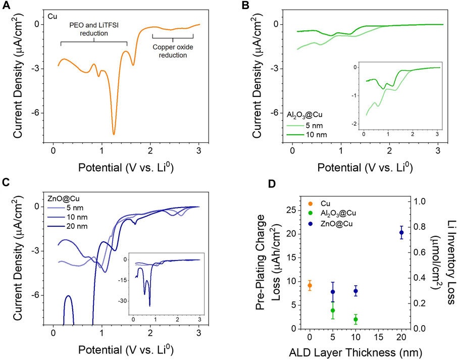
FIGURE 1. Electrochemical Reactivity of ALD Coatings. (A–C) LSV of half cells with PEO-LiTFSI electrolyte at 60 °C with a scan rate of 0.2 mV/s with (A) Cu, (B) Al2O3@Cu, and (C) ZnO@Cu electrodes. Insets in (B) and (C) show the LSVs on a better scale to view differences from Cu. (D) Integrated charge prior to lithium plating from voltammetry and galvanostatic cycling at 10 µA/cm2 as a function of ALD coating thickness; the charge is converted to functional lithium loss per unit area on the right axis. Points and error bars represent the average and standard deviation of two to 4 cells.
A combination of Li deposition and subsequent surface analysis was performed in a home-built ultra-high vacuum (UHV) system (10−10 mbar of base pressure) where a glove box, a surface analysis module, and a physical vapor deposition (PVD) module are interconnected through a UHV linear transfer system to avoid any air exposure. Samples were initially mounted in a glove box and transferred to the surface analysis module. X-ray photoelectron spectroscopy (XPS) was performed using a Specs PHOIBOS 150 hemispherical energy analyzer with a monochromatic Al K
Time-of-flight secondary ion mass spectrometry (ToF-SIMS) imaging and depth profiling analysis were carried out using a commercial ToF-SIMS instrument (M6, IONTOF, Münster, Germany). A focused 30 keV Bi3+ primary (probing) ion beam was generated by a pulsed liquid metal ion gun (LMIG) equipped with a Wien filter (∼0.26 pA current internal to the LMIG). Depth profiling was performed by sputtering a 1 keV beam of O2 from a dual source ion column (DSC-S) equipped with a Wien filter with total sample exposure of 2.8 × 10¹⁷ ions/cm2 (∼250 nA current internal to the DSC-S). The primary beam raster size (pixels) was 128 μm × 128 µm with a field of view of 50 μm × 50 µm and a sputter beam crater size of 300 μm × 300 µm. The flood gun was kept on during the measurements in order to manage surface potential by reducing sample charging. Cycled, rinsed, and dried samples with plated lithium sealed in coin cells were opened in an argon filled glove box, mounted with copper tape on a top-mount sample plate, and placed in an air-tight sample transfer box. Thus, samples were not exposed to air at any point in time. Five data sets were collected at different regions on each sample, with continuous collection of ToF-SIMS data during continuous DSC-S sputtering for 160 s to obtain the depth profiles. All the 3D images and depth profiles were generated using SurfaceLab 7.3.134065 with ion signals plotted as recorded, without normalization.
The cycled sample morphology was characterized using scanning electron microscopy (SEM) via secondary electron imaging in a Thermo Fisher 5CX Helios SEM-FIB. Prior to imaging, samples were transferred from an Ar glovebox into the SEM using an air-free transfer workflow. The sample was prepared and loaded into a transfer container in the Ar-filled glovebox. The transfer container was then cooled in a liquid nitrogen bath to liquid nitrogen temperature with the sample inside. The cooled container was opened to N2 atmosphere, exposing the sample to nitrogen gas only at liquid nitrogen temperatures. The sample was then quickly transferred into a vacuum cryo transfer system (Leica EM VCT500), maintaining an atmosphere of cold N2 and a temperature below −140°C, before the cold N2 gas was pumped out. The cooled transfer shuttle was then connected to the chamber of the SEM and the sample transferred in vacuum to the SEM stage, which was also cooled to liquid nitrogen temperatures.
During characterization, imaging was performed using a beam voltage of 5 kV and a current of 0.69 nA. Energy dispersive spectroscopy (EDS) was conducted using an Oxford detector to confirm the elemental distribution of the Cu substrate, coatings, and plated products. EDS measurements were done using different voltages, including 5 kV and 20 kV, under a high beam current such as 0.69 nA. The depth and density of the plated products were also investigated with focused ion beam (FIB) milling, where Ga ions were used at a voltage of 30 kV and a current range of 1–47 nA. Larger currents were used to do rough milling of a larger volume, while lower currents were used to do fine polishing and cleaning of the cut cross-sectional area. After milling and polishing, the exposed cross-sections of the grown products were imaged and analyzed with EDS.
To begin interrogating the effect of oxide coating layers in SSBs, we tested a simple PEO-LiTFSI solid polymer electrolyte with Cu, Al2O3@Cu, and ZnO@Cu electrodes. Copper, a metal that shows very little alloying with lithium metal under these conditions (Rupp et al., 2019; Huang et al., 2023), was tested with the native oxide untouched to ensure better comparison to the artificial metal oxides deposited with ALD. PEO-LiTFSI was used as a solid electrolyte for two main reasons. First, it is a well-studied, versatile solid electrolyte system that is simple to fabricate (Xue et al., 2015). Second, unlike other solid electrolytes that suffer from electrode contact loss during cycling due to their hardness and inflexible nature, PEO-LiTFSI should provide a soft electrode-electrolyte interface that maintains contact throughout the cell lifetime (Janek and Zeier, 2016; Homann et al., 2020). This enables us to exclude delamination between the electrode and electrolyte as a failure mode here.
Figures 1A–C shows representative LSVs for Cu with native oxide, 5 and 10 nm Al2O3@Cu, and 5, 10, and 20 nm ZnO@Cu. The reductive charge passed, as integrated from voltammetry prior to 0.0 V vs Li0 (the onset of lithium plating), is shown in Figure 1D and is analogous to the charge lost during the formation step in a practical battery (An et al., 2016; Mao et al., 2018). On the surface of Cu with native oxide, we observed two distinctive groups of reduction signals: reduction of native oxide above 2.0 V vs Li0 and SEI formation from LiTFSI and PEO at around 1.2–1.4 V and 0.8–0.9 V vs Li0 (Ushakova et al., 2022). With Al2O3 coatings, much lower current densities (<2 µA/cm2) and reductive charges than Cu electrodes are seen, with current density and charge decreasing with increasing coating thickness (Figures 1B,D). We observed reduction signals only below 2.0 V vs. Li0, with the lack of CuOx reduction indication that any pinholes in the film that would expose bare Cu are very small in area. The lower current densities agree with the expected, extremely low electronic conductivity of Al2O3 (10−16 S/cm) (Kusunose et al., 2019) that hinders electron transfer to the electrolyte.
In contrast, ZnO@Cu electrodes show similar magnitude of current densities to the Cu electrode (2–7 µA/cm2) with peaks related to PEO-LiTFSI reduction and ZnO reduction below 1.5 V. The presence of reduction peaks above 2.0 V might be related to exposed CuOx caused by non-conformal coatings, especially with thinner ZnO. Regardless, the larger current densities from 5 to 20 nm ZnO compared to Al2O3@Cu indicate that ZnO layers of any thickness have functionally high electronic conductivity (likely in the range of 100 S/cm) (Elam et al., 2003), since electrons can move from the Cu current collector to the electrolyte interface and replicate the same current density as unmodified Cu. Additionally, 20 nm ZnO@Cu shows higher current densities and charges related to oxide reduction and alloying (Figure 1C inset), as discussed later. It was also observed with voltammetry that the native oxides on Al and Zn foil electrodes behave similar to ALD coatings—aluminum oxides are electronically insulating and lead to low current densities, while zinc oxides are electronically conductive and show similar SEI formation current densities as copper electrodes (Supplementary Figure S2).
Figure 1D shows that coating Cu with Al2O3 lowers the lithium inventory loss, while coating with ZnO tends to increase this loss. From a practical perspective, the Al2O3@Cu electrodes would be desirable in anode-free SSBs since the lithium inventory loss during SEI formation is reduced by at least 50% compared to Cu alone, thus increasing the usable capacity after the formation step. Although the 2–22 µAh/cm2 lithium losses reported here are small compared to the >3 mAh/cm2 required for practical applications (Albertus et al., 2018), this is related to total electrode surface area, not just geometric area. For 3D structured anodes (Park et al., 2020; Pathak et al., 2021), this lithium loss number quickly rises compared to the planar 2D electrodes used here, significantly eating into the usable capacity. Since ALD is a useful process for the conformal coating of 3D structures, developing ALD coatings as artificial SEIs may be a valuable strategy for limiting lithium loss with 3D structured electrodes (Kim et al., 2017).
The origin of this lithium loss may be different as well as the coating chemistry changes. Cu electrodes lose charge solely to SEI formation and oxide reduction if the native oxide is present (∼0.3 µAh/cm2 oxide reduction is seen here). Al2O3@Cu could lose charge to SEI formation and reduction of the Al2O3 coating. Assuming the maximum of a three-electron transfer to every Al3+ ion in the coating, the estimated charge is 1.0 µAh/cm2 for 10 nm Al2O3@Cu (approximately 0.1 µAh/cm2 per 1 nm Al2O3). Given the difficulty of reducing Al2O3, the lack of clear peaks in voltammetry, and the observed charge being at least 2 µAh/cm2 for all coatings, some or all charge must go towards SEI formation. This is observed with the small peaks in Figure 1B being in the same potential range as PEO-LiTFSI reductions peaks seen with Cu electrodes. For ZnO@Cu, charge is also lost through SEI formation and the reduction of ZnO. Assuming a two-electron transfer to every Zn2+ ion in the coating, the estimated charge for 20 nm ZnO@Cu is 5-8 µAh/cm2 (approximately 0.4 µAh/cm2 per 1 nm ZnO). This helps explain why charge loss is greater with ZnO over Cu, as the ZnO is much more redox active than Al2O3, and the electronic conductivity of ZnO@Cu coatings explains a similar charge (∼9 µAh/cm2) being lost to SEI as with bare Cu (Figure 1D). The reduction charge of 20 nm ZnO@Cu electrodes (20 µAh/cm2) may be larger than the straight addition of SEI and ZnO reduction charges (estimated 14–17 µAh/cm2) due to the increased surface area after reduction causing more SEI formation than expected based on the geometric area; see the Discussion section below.
As demonstrated above, the electronic conductivity of the ALD layers can control capacity fade by limiting or increasing the amount of charge lost before lithium plating. In addition to electronic differences that contribute to battery lifetime, these interface layers have different ionic conductivities that control the effective cell resistance, which affects the energy efficiency and power density of the battery during operation. This interface resistance is expected to change as the coatings undergo (electro)chemical changes. Figure 2A shows the modulus of impedance, |Z|, calculated at 1 Hz from impedance data before any electrochemistry was performed in the cell. This represents a rough estimate of the cell impedance at an un-pinned open circuit potential, which can be increased if the ALD coating is resistive even in the absence of a redox process. With the resistive Al2O3 coatings, the impedance modulus is at least triple that of Cu alone (56 kΩ cm2). Meanwhile ZnO coatings have little effect (within error) on the impedance, again indicating their conductive nature.
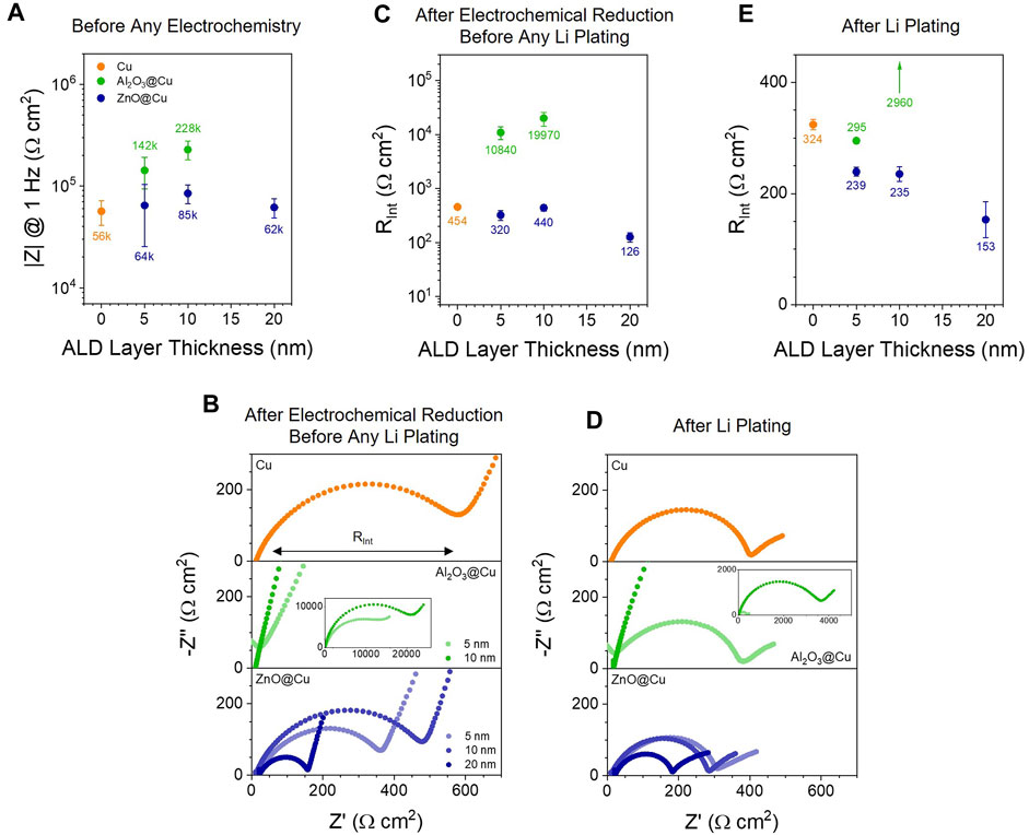
FIGURE 2. Impedance of ALD Layers during Operation. (A) Estimated impedance modulus at 1 Hz from impedance data (Supplementary Figure S3) taken before any charge was passed in the cell. (B) EIS Nyquist plots of representative half cells with PEO-LiTFSI electrolyte at 60 °C after voltammetry; EIS here was performed at 0.1 V DC bias. (C) Estimated interface resistance from the data in (B). (D) EIS Nyquist plots of the cells from (A) after plating 50 µAh/cm2 Li at 10 µA/cm2; 10 nm Al2O3@Cu was limited to 1 µAh/cm2 Li at 1 µA/cm2 to prevent shorting before the measurement. (E) Estimated interface resistance from the data in (D). Number labels show the average RInt values for the electrode type. Points and error bars represent the average and standard deviation of at least 2 cells; the upward arrow in (D) indicates a single data point for 10 nm Al2O3@Cu is off the graph at 2,960 Ω cm2.
Figures 2B,C show impedance data and interface resistance (RInt) values following electrochemical reduction to form the SEI and/or react the ALD coatings following the voltammetry in Figure 1. RInt is represented by the medium-frequency semicircle apparent in all Nyquist plots in Figure 2B and is taken to be the sum of the formed SEI’s and the coating layer’s resistances. Following electrochemical reduction before the onset of Li plating, RInt values on the Cu electrodes are around 450 Ω cm2 and reflect the resistance of the SEI layer. ZnO@Cu electrodes show overall lower impedances (300–450 Ω cm2 for 5–10 nm ZnO@Cu), especially with 20 nm ZnO@Cu (around 126 Ω cm2). RInt values for 10 nm ZnO coatings are slightly higher than 5 nm ZnO@Cu coatings, which may be due to the thicker Li2O layer formed from the ZnO conversion (vide infra), effectively increasing the SEI thickness. The decrease from 5 to 10 nm ZnO@Cu to 20 nm ZnO@Cu may be related electroactive surface area increases (thus lowering the geometric area resistance RInt) alluded to above. On the other hand, Al2O3@Cu electrodes have RInt values exceeding 10 kΩ cm2 after going to reducing potentials, indicating that these layers have very slow ion transport (slower than the SEI alone), as RInt reflects the conductivity of ions (i.e., Li+) through the electrolyte-surface layers-electrode interfaces.
After electrochemically reducing the interface to form the SEI and reduce the ALD coatings as much as possible with applied potential, lithium metal was plated with galvanostatic cycling (Supplementary Figure S3). Once Li present at the interface, there is the possibility of further chemical reduction of the coating. Impedance data for the same half cells with Li metal plated are shown in Figure 2D & 2E. For Cu electrodes, the impedance decreases slightly (by ∼130 Ω cm2), something we often observe once Li is on the surface and the potential of the working electrode is pinned to that of a stable redox couple (Li+/0). The greatest changes are seen for Al2O3@Cu after Li plating, where the RInt for 5 nm Al2O3@Cu is 37-fold decreased to around 295 Ω cm2, similar to that of Cu and ZnO@Cu electrodes. This could be attributed to reaction of the coating to increase Li+ transport through Al2O3 or to large surface areas of now-exposed lithium electrode, mechanisms that will be discussed more below. For 10 nm Al2O3@Cu, the interface resistance after Li plating is still several kΩ cm2 due to slow Li+ conductivity and low electronic conductivity through the layer, and many cells short due to dendrite formation before enough lithium can be plated to get a reliable EIS measurement. As with electrochemical reduction (Figure 2B), ZnO@Cu electrodes show lower RInt values than Cu alone, and RInt decreases with increasing thickness.
To further understand the chemical reactivity of the ALD coatings upon Li contact, we compared the surface chemistries before and after Li deposition via e-beam evaporation. A combined XPS and Li deposition protocol in the ultra-high vacuum system (described in the Materials and Methods section) used previously in numerous solid electrolyte systems (Zhu et al., 2019; Connell et al., 2020; Liu et al., 2022) was applied to rule out air exposure or undesired surface contamination. Surfaces of as-prepared Al2O3@Cu and ZnO@Cu samples were initially examined via XPS prior to the Li deposition, and the Li-deposited surfaces were subsequently analyzed via XPS again.
Core level spectra and optical images of the Al2O3@Cu and ZnO@Cu surfaces before and after Li deposition are shown in Figure 3. For Al2O3@Cu, a clear Al2O3 signal at 74.2 eV is observed in Al 2p core level spectra on the pristine surface (Figure 3A, top), with superpositioned Cu 3p core levels derived from the Cu substrate (Cu0 and Cu2O at 74.8 eV and CuO 76.7 eV) (Khalakhan et al., 2021). Upon contact with Li0, we observed a decrease in Al2O3 peak intensity and a new peak emerging at 73.5 eV, which we tentatively assign as LiyAlOx (Figure 3A, bottom). This shift is commensurate with Al2O3 coatings grown directly on lithium metal (73.2 eV) (Chen et al., 2017) and coatings on argyrodite solid electrolytes in contact with lithium (73.4 eV) (Hood et al., 2023). Meanwhile, ZnO shows a more distinct and clear reduction reaction with Li0 (Figure 3B). The surface of the as-prepared ZnO@Cu shows a ZnO signal at 1022.1 eV in Zn 2p3/2 core level spectra (Figure 3B, top), while the Li-deposited surface mainly exhibits alloying between Zn and Li to form a reduced peak at 1020.5 eV along with some residual ZnO (Figure 3B, bottom).
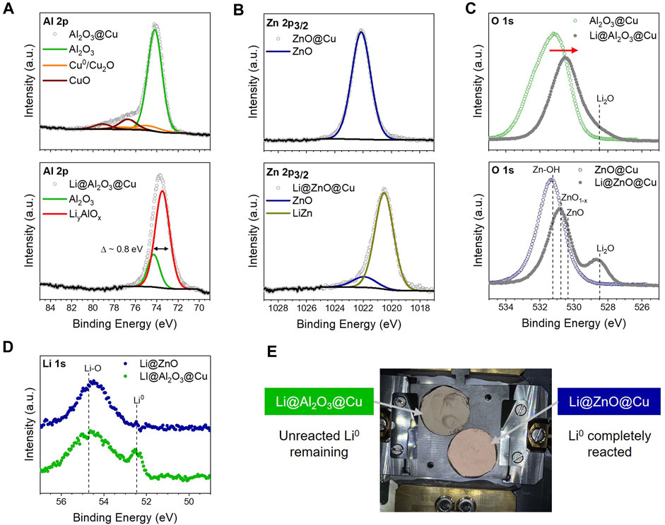
FIGURE 3. Chemical Reduction of Oxides Layers upon Li deposition. (A) Al 2p core levels of 2 nm Al2O3@Cu before (top) and after (bottom) Li deposition on top of the ALD layer. (B) Zn 2p3/2 core levels of 3 nm ZnO@Cu before (top) and after (bottom) Li deposition on top of the ALD layer. (C) Comparison of the O 1s core levels of both ALD layers after Li deposition (D) Comparison of the Li 1s core levels of both ALD layers after Li deposition. (E) Photograph of the samples after Li deposition.
The O 1s and Li 1s core level spectra corroborate these mechanisms of the Li-derived reaction. In Figure 3C (top) and Supplementary Figure S4c, the O 1s core level spectra of Al2O3@Cu show a typical Al2O3 feature with surface hydroxyls and some residual carbon-oxygen species at higher binding energies. This oxygen signal overall shifts to lower binding energies upon lithium deposition, indicating partial reaction of the ALD Al2O3 coating leading to a more reduced environment (in agreement with the Al 2p spectra). Due to the complexity of O 1s core level spectra, especially for metal oxides, in-depth deconvolution of this narrow binding energy range is challenging (Supplementary Figure S4c). Some lithium oxide species may form at the Li-Al2O3@Cu interface as well, as apparent at lower binding energies (Figure 3C, top). We assume that the lithium oxide species mainly consist of Li-OH and Li-O bonding, which we carefully speculate originated from the residual hydroxyl species on the ALD Al2O3 surface that reacted upon Li deposition and not necessarily from the Al2O3 layer, although this is worth investigating in future.
A similar trend is seen in the O 1s core level spectra on the ZnO@Cu surfaces, as shown in Figure 3C (bottom) and Supplementary Figure S4d. The as-deposited coating contains Zn-OH and sub-stoichiometric ZnO1-x in addition to ZnO. Oxygen vacancies in the ZnO coating might explain the high electronic conductivity of the coated electrode, leading to the trends in Figures 1C,D and Figure 2. Upon Li deposition, we observed the same overall shift of the O 1s spectra to lower binding energy like with Al2O3@Cu, this time with a clear Li2O signal emerging at 528.5 eV, as shown in Figure 3C (bottom). This indicates a near-complete conversion reaction of ZnO@Cu in contact with Li.
In the Li 1s core level spectra (Figure 3D), metallic Li is observed at 52.5 eV on the surface of the Li-deposited Al2O3@Cu, while the ZnO@Cu surface does not show any evidence of this after Li deposition. Given the asymmetric shape of the peak at 54.7 eV on the Li-deposited Al2O3@Cu surface, we speculate a co-existence of LiyAlOx and Li oxide species, which is consistent with the Al 2p and O 1s core level spectra. The Li-deposited ZnO@Cu surface exhibits a major signal at 54.5 eV with a small shoulder at 53.7 eV, which is probably derived from a combination of Li2O formation and Li-Zn alloying, respectively. These results suggest that while both chemistries show reactivity upon Li deposition, Al2O3 coatings react in a self-limiting way to form a LiyAlOx phase that eventually becomes stable to Li0, while ZnO undergoes a full conversion reaction to LiZn alloy and Li2O, something seen visually in Figure 3E. These differences in reactivity help to explain both the trends in pre-plating charge in Figure 1D and differences in initial interfacial impedance in Figure 2.
Given the differences in (electro)chemical reactivity between Al2O3 and ZnO, these coatings should change how lithium metal plates during battery charging. This can initially be quantified by looking at the nucleation and growth overpotentials in the first plating step (Figure 4A). Here, we quantify ηNucleation as the magnitude of the peak voltage of the first plating step; the absence of lithium prior to this step is crucial both for the definition of nucleation overpotential (as discussed in-depth by Yu et al.) (Yu et al., 2023) and to show how electrochemical reduction of the oxide coatings affects Li nucleation.
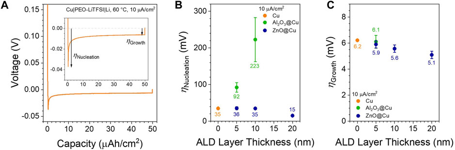
FIGURE 4. Lithium Plating Overpotentials. (A) Example of the initial plating step in a Cu||Li half cell with PEO-LiTFSI at 60 °C with 10 µA/cm2 applied current density. The nucleation and growth overpotentials referenced in the rest of the text are noted. (B) Nucleation overpotentials as a function of coating thickness on the initial plating step. (C) Growth overpotentials as a function of coating thickness on the initial plating step. No growth overpotentials are shown for 10 nm Al2O3@Cu due to consistent cell shorting. Points and error bars represent the average and standard deviation of at least 2 cells.
The nucleation overpotentials quantified in Figure 4B follow the impedance data in Figure 2—there is little difference between Cu and thin ZnO@Cu (ηNucleation ∼35 ± 4 mV for 0–10 nm thickness) but a relatively large decrease when increasing the ZnO thickness to 20 nm (15 ± 1 mV), while Al2O3@Cu increases the overpotential drastically with increasing thickness (up to 223 ± 60 mV at 10 nm thickness). This reflects the relative ionic conductivities of the interface layers following electrochemical reaction (Figure 2C), which will determine the cell voltage at the early Li plating stage through Vcell = Iapplied × Rcell (Rcell will be mainly controlled by RInt as apparent by the larger interface vs small bulk semicircles in the Nyquist plots, Figures 2B,D). Surprisingly, the growth overpotentials show virtually no difference (ηGrowth ∼ 6 mV) between all coating conditions (Figure 4C), with only a slight drop in overpotential with increasing ZnO thickness (down to 5.1 mV) in line with the impedance in Figure 2E. This indicates that the initial plating dictated by either the reacted Al2O3 or the converted ZnO surfaces is probably not a governing factor of the Li growth reaction at longer times, as another mechanism takes over under these conditions.
To visualize the differences in coating reactivity and lithium plating behavior between Al2O3@Cu and ZnO@Cu, we employed ToF-SIMS and SEM-FIB imaging. ToF-SIMS provides spatially resolved chemical analysis of the anode interface, while SEM-FIB directly characterizes the plated Li 3D structure. To prepare better samples for post-mortem analysis, the PEO-LiTFSI solid electrolyte in Cu||Li half cells was replaced with a liquid electrolyte (1 M LiFSI, 1 M LiNO3 in DME) and cycled at room temperature so the anode could be rinsed well and expose the plated lithium with minimal disruption or corrosion. For each electrode, 1 mAh/cm2 was plated at 10 µA/cm2 after initial formation plating and stripping steps at 0.1 mAh/cm2, 10 µA/cm2. The cell was then disassembled, rinsed with pure DME solvent, dried, and stored in closed containers in the glovebox before analysis.
Three-dimensional ToF-SIMS images in Figures 5A,B highlight the ALD layer while contrasting the differences in lithium plating for Al2O3 vs ZnO. With Al2O3@Cu, the ALD layer has Li integrated into the Al2O3, detected as LiAlO+ and other Li-containing ions (Figure 5A and Supplementary Figure S5 and Supplementary Figure S6). Within and mainly under this LiyAlOx layer, small amounts of lithium metal exist as evident from the Li3+ signal (Counihan et al., 2023), especially in the depth profile (Figure 5B). Importantly, there is no Li on top of the LiyAlOx layer (Region A1), indicating no appreciable electronic conductivity in this layer relative to other regions on the electrode. Instead, in regions where lithium is seen plated in large amounts, it appears in a distinct Li/LixAlOy/Cu triple interface (Region A2). This may result from the lithium metal plating onto the copper then breaking through the ALD coating or from lithium plating at pinholes in the coating, as discussed later. More than one region with lithium metal deposits exhibited this behavior, indicating this could be a prominent mechanism for lithium plating with Al2O3 coatings (Supplementary Figure S7). Finally, the bottom of Region A1 shows that the DSC-C has sputtered through completely to metallic copper, as evident from the Cu3+ signal, while Region A2 only shows metallic copper in the part of the bottom region where metallic lithium plated onto the copper and broken through the ALD coating; presumably the lithium metal is thick enough in that region that the copper substrate was not exposed during the short sputtering time.

FIGURE 5. ToF-SIMS at the Anode Interface. (A) ToF-SIMS 3D images of 1 mAh/cm2 lithium metal plated with a 5 nm Al2O3@Cu electrode at two separate regions on the electrode’s surface. The detected ions are labelled with lines. (B) Depth profile of Region A1 averaged over the image cross section at a single depth (sputter time). (C) ToF-SIMS 3D images of 1 mAh/cm2 lithium metal plated with a 5 nm ZnO@Cu electrode. Both images here show the same region with different ion maps for clarity. (D) Depth profile of Region Z1 averaged over the image cross-section. All ToF-SIMS images are 50 × 50 µm in the lateral X-Y dimensions, and the Z-axis (<1 µm) is stretched for clarity. See Supplementary Figure S5-S8 for additional ToF-SIMS data.
With ZnO@Cu, no plating below the coating or triple interfaces were observed (Figure 5B, Region Z1). Rather, all Li was detected above a Zn-rich layer that separated the deposited lithium and copper metal substrate. This was detected as LiZnO+ and Zn+ separately. Note that sputtering with the DSC-S will form oxide species and lead to the appearance of LiZnO+ during Bi3+ sputtering, or it may form directly from an existing LiZn-Li2O mixture. However, XPS does not detect any “lithiated zinc oxide” structure present here. This also applies for the Li-Al2O3 mixtures in Figure 5A, but since XPS detects a different chemical species (Figure 3A), we assume for now that LiAlO+ results from a specific species, LiyAlOx. Importantly, the Zn+ is concentrated exclusively between the Li3+ and Cu3+ interfaces, i.e., virtually no zinc dissolves into the lithium phase as it stays in the converted LiZn layer. This is important from a mechanistic standpoint, since other anode-free designs with alloying metal interlayers can involve metal dissolution into the plated Li and exsolution during Li stripping (Lee et al., 2020; Sandoval et al., 2023). Finally, the bottom of Region Z1 shows that the DSC-S has sputtered through completely to metallic copper, albeit with small amounts of alloyed Li(Huang et al.; Rupp et al., 2019) (which are also present with copper in Region 1 and part of Region 2).
To visualize the structure of lithium deposits on a larger level, we used SEM-FIB. Figure 6 shows the morphology of the plated lithium on the same Cu, 5 nm Al2O3@Cu, and 5 nm ZnO@Cu electrodes as Figure 5. Panel i is a low-magnification image of the sample surface, panel ii is a higher-magnification image of the Li morphology, and iii is an image of the cross-section after milling and polishing for each electrode. In general, the plated Li forms circular, flower-like patches on all three electrodes, appearing in the SEM images with a darker contrast than the Cu or coated Cu substrates due to its low Z value (Goldstein et al., 2018).
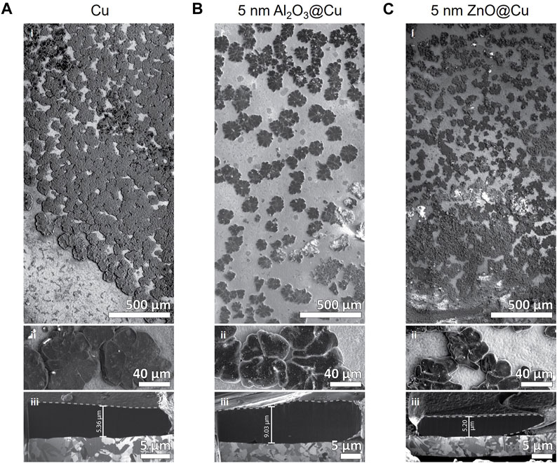
FIGURE 6. SEM-FIB Imaging of the Anode Interface. (A–C) SEM images of 1 mAh/cm2 lithium metal plated on (A) Cu, (B) 5 nm Al2O3@Cu, and (C) 5 nm ZnO@Cu electrodes. Different panels represent i) large area montage image of the electrode, ii) higher magnification on lithium deposits, and iii) cross-section image of a FIB-milled lithium deposit.
The image scales of Figures 6A–C,I are the same, and the differences between the sizes and morphology of the plated Li can be directly observed. The Li plated on Cu appears in clusters interconnected with each other, covering around 73% of the surface area measured (Figures 6A,I). Meanwhile, Li plated on 5 nm Al2O3@Cu surfaces forms individual, separated clusters (Figures 6B,I) and covers only around 36% of the electrode area on average. For Li on 5 nm ZnO@Cu, the average coverage is around 61%, and the clusters grow to be both separated and connected (Figures 6C,I).
The images in Figures 6A–C, 6ii are again all shown in the same magnification. The Li growth morphologies are similar to each other, forming circular flower-like clusters that are joined together by several “petals”. The size differences can be observed in these images as well, where the clusters grow largest on bare Cu (Figures 6A, 6ii) and smallest on 5 nm ZnO@Cu (Figures 6C, 6ii). Supplementary Figure S9 shows histograms of the Li clusters on the surface of 5 nm Al2O3@Cu and 5 nm ZnO@Cu, which quantitatively shows the distribution of the deposits. ZnO@Cu electrodes especially show very small Li cluster sizes (areas <10−3 mm2).
Figures 6A–C, 6iii show the cross-sectional view of a randomly selected, yet representative, Li cluster on each electrode. An averaged thickness marker is included in each image, where the measured Li growth thickness is around 5.36 µm on Cu, 9.03 µm on 5 nm Al2O3@Cu, and 5.20 µm on 5 nm ZnO@Cu. The dark contrast is the Li layer, whereas the layer underneath with grains is the Cu substrate in each case. EDS signal confirms the position of Cu, and the lack of signal in the dark layer confirms it is a low Z element, specifically Li, as shown in Supplementary Figure S10. The nearly double thickness of Li deposits on 5 nm Al2O3@Cu compared to Cu and 5 nm ZnO@Cu corroborate the reason for the lower coverage area observed in the lower magnification images. Since 1 mAh/cm2 Li (∼5 µm theoretical thickness) is plated in all cases, Li must be accumulated on the sparsely formed Li clusters on 5 nm Al2O3@Cu, as opposed to growing freely on the underlying conductive surfaces of Cu and 5 nm ZnO@Cu.
In totality, all factors like interface resistance, overpotentials, and chemical differences that influence lithium plating will impact the performance of the battery. Two key metrics for battery performance are lifetime and charging rate, which are often tested at the lab scale by quantifying Coulombic efficiency and critical current density, respectively. Along these lines, we performed a series of plating and stripping measurements in Cu||Li half cells with PEO-LiTFSI electrolytes for all coatings. The testing protocol, known as the reservoir or Adams method (Adams et al., 2018; Mohammadi et al., 2023), follows that of Figure 7A: 50 µAh/cm2 of lithium is plated and stripped, the same charge is re-plated, then 20% of this charge is stripped and plated for several cycles before a final stripping step. A small charge was used to avoid shorting the cells before useful information could be extracted, as will become evident. Each cell was run using this protocol at 10 µA/cm2, then the protocol was repeated at increasing 10 µA/cm2 increments until the cell shorted.
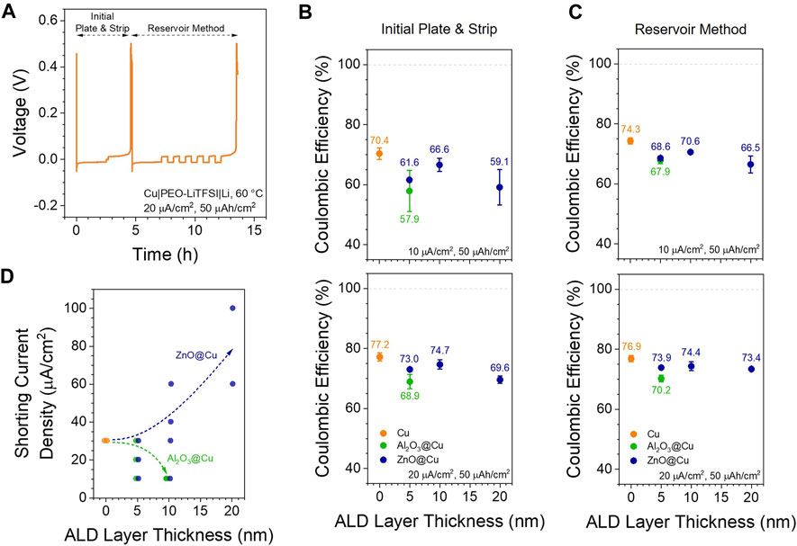
FIGURE 7. Cycling Performance. (A) Example of the cycling protocol used to quantify Coulombic efficiency at different current densities in Cu||Li half cells with PEO-LiTFSI at 60 °C (B–C) Coulombic efficiencies calculated from (B) the initial plate and strip steps and (C) the reservoir method steps at 10 (top) and 20 (bottom) µA/cm2 (D) Current density at which cells shorted during the protocol in (A). Dashed arrows are drawn to guide the eye. Each point represents an individual cell, with overlapping cells offset slightly on the x-axis for clarity.
The current density during which the cell shorted will be referred to as the “shorting current density”, which we differentiate slightly from the common “critical current density” determined under different current or voltage ramp testing conditions (Sharafi et al., 2016; Flatscher et al., 2020; Gopal et al., 2023). The Coulombic efficiency (CE) of the initial plate-strip step and the reservoir step were quantified separately, following:
where Qinitial strip and Qinitial plate are the respective charges from the first two steps, Qplate is the reservoir charge, n is the number of 20% strip-plate steps, and Qfinal strip is the charge from the last reservoir stripping step. We chose to quantify both CE values since CEInitial will reflect charge loss from lithium plated from the base ALD coating layer, while CEReservoir will reflect charge loss from lithium plated on existing lithium.
Figures 7B,C compare CEInitial and CEReservoir as a function of ALD coating thickness at 10 and 20 µA/cm2 current densities. Although these are still well below the >99% values needed for practical batteries, this low Coulombic efficiency of lithium metal is known for solid polymer and composite electrolytes (Counihan et al., 2023) and is an active area of exploration. CEs of the 5 nm Al2O3@Cu show a 7%–13% decrease as compared to the CEs of Cu, and 10 nm Al2O3@Cu cells failed before plating even 50 µAh/cm2 at 10 µA/cm2. All ZnO@Cu electrodes performed more similarly to unmodified Cu, though still with 4%–11% lower CE values. At each current density tested, CEReservoir was almost always equal to or greater than CEinitial (Supplementary Figure S11). Although this is somewhat expected given the protocol differences (Mohammadi et al., 2023), this indicates that under these conditions, there is at least no particular charge efficiency benefit to plating onto the base ALD coating compared to a lithium reservoir and that keeping a lithium reservoir may even boost CE slightly (Fang et al., 2021). Somewhat surprisingly, in all cases, unmodified Cu electrodes show the highest CE values. Although there is a noticeable decrease in CE when the thickness of ZnO@Cu is increased from 10 to 20 nm, 20 nm ZnO@Cu still shows the same or higher CE than 5 nm Al2O3@Cu. This is opposite of the impedance and overpotential trends above and in contrast to the trend observed by Mohammadi et al. (Mohammadi et al., 2023), where increasing the ZnO thickness on Ni current collectors increased the CE in liquid electrolytes. Such a finding points to the differences between liquid and solid electrolytes and the many unique challenges in the solid electrolyte field. Charge loss due to Li trapping in the LiZn phase (Rehnlund et al., 2017; Crowley et al., 2022; Liu et al., 2023) is unlikely to contribute much to this, since the alloy layer is so thin and the cycling protocol includes potential holds to strip and de-alloy as much as possible.
Finally, the shorting current densities observed across all tested cells are shown in Figure 7D. With Al2O3 coatings, the accessible current density drops off drastically with increasing thickness and is no better than the baseline Cu electrodes (30 µA/cm2). In contrast, ZnO coatings offer a general increase in achievable current density, with 20 nm ZnO@Cu (60–100 µA/cm2) doubling or tripling that of Cu alone and Al2O3@Cu. This may be related to a higher surface area and/or better nucleation sites on LiZn clusters compared to Cu, leading to less lithium filament and dendrite formation. The low Coulombic efficiencies with all electrode types point to the limitations of this simple PEO-LiTFSI electrolyte system, where other problems relating to lithium metal stability need to be addressed.
Given the above results, we postulate two distinct mechanisms for Li plating on Al2O3@Cu and ZnO@Cu (Figure 8) and discuss their effects on battery performance. We can describe these two mechanisms generally. In Mechanism 1, a metal or metalloid forms strong bonds to oxygen and is relatively unreactive to Li metal. The ALD coating remains as a metal oxide, though with varying amounts of lithium, after (electro)chemical reaction. In Mechanism 2, a metal or metalloid is readily reduced or reactive to lithium metal in its oxide form, converting completely to the metal or lithium-metal alloy and lithium oxide. Since the redox potentials of most metal ions are positive of Li0, we believe the metal-oxygen bond strength will be a primary factor in determining the stability of the metal oxide, at least kinetically, and exhibiting Mechanism 1 vs 2 for a given material.
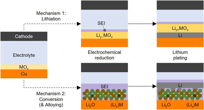
FIGURE 8. Mechanisms of Lithium Plating with ALD Metal Oxide Coatings. Proposed mechanisms for lithiation (top) and conversion and alloying (bottom) of metal oxide coatings in anode-free lithium metal batteries. The first step shows changes during electrochemical reduction in the formation step prior to the lithium plating onset, and the second step shows chemical reduction by plated lithium and growth of the lithium layer. Liy–MOx transforming to Liy+MOx indicates that chemical reduction by plated Li0 may lithiate the oxide more than electrochemical reduction. Irregular lithium shapes in the bottom right figure indicate Li metal initially growing from (Liy)M. See Supplementary Figure S12 for mechanisms accounting for emergent defects and pinholes.
When reducing these metal oxides electrochemically (potentials greater than 0.0 V vs Li+/0) or chemically with Li0, the reaction pathway will be determined primarily by this bond strength difference. In Mechanism 1, if the metal ion reduces and Li+ enters the structure, the M-O bond will not break, leading to a stable lithiated structure:
It has also been hypothesized that Li+ can enter the structure without any permanent redox reaction taking place due to space charge or other effects (Cheng et al., 2020):
For discussion purposes, we will refer to both of these pathways as “lithiation”, one with and one without redox processes occurring.
In Mechanism 2, a complete conversion reaction will be seen: M is reduced to its metallic state, and Li+ ions replace its bonds with oxygen, leading to:
If the metal is able to alloy with lithium, it will form the alloy(s) appropriate for the metal-lithium mixture, possibly in a concerted mechanism during the conversion step:
These last two pathways are known in the field of conversion anodes (Bresser et al., 2016; Puthusseri et al., 2018; Marques et al., 2023). This “lithiation” vs “conversion”, along with electronic conductivity of the coatings, is at the heart of the differences between Al2O3@Cu and ZnO@Cu.
When MOx lithiates to LiyMOx, the ionic conductivity of Li+ through the layer increases, as shown in Figure 2B. However, the maximum level of lithiation might only be achieved by chemical reduction with Li0, as shown in Figure 2D & 3. This is represented in Figure 8 (top) with the electrochemically reduced Liy–MOx lithiating further to Liy+MOx in the presence of Li0. The exact Li content likely varies depending on the metal center, and it may be possible to undergo further lithiation and phase decomposition to form lithium oxides (i.e., driving Mechanism 1 partially or completely to Mechanism 2), although this needs more study to confirm.
Al2O3 is a popular coating choice for lithium batteries, mainly on the cathode side due to its oxidative stability (Park et al., 2014; Cheng et al., 2020). Its reductive stability is less well-known and under debate. It is difficult to rationalize an Al3+ cation reducing to Al2+ or Al1+, and Al0 would not be stable within the oxide structure and is not observed experimentally in Figure 3. XPS clearly shows a shift to lower binding energies for both Al, O, and Li species (Figure 3A; 3C; 3D), indicating a reduced environment for all of those elements. Whatever reaction does occur between Li0 and Al2O3 appears to be self-limiting, as apparent here and in the work of Fan et al., who showed experimentally that reacting Li0 and Al2O3 particles yields a thin (∼2 nm) LiyAlOx layer on the particle surface (Fan et al., 2018). Given the 3 nm thickness but incomplete reaction of our ALD Al2O3@Cu in Figure 3, it is reasonable to assume this reaction also self-limits at ∼2 nm with ALD Al2O3. In support of the direct reduction of Al2O3 by Li0 is work by Jung and Han, predicting that as Al2O3 incorporates Li atoms (electrons and ions), Li replaces Al as the metal coordinating to O (Jung and Han, 2013). This causes increased Al-Al interactions resembling multi-atom clusters, a process thermodynamically favorable up to Li3.4Al2O3 and nominal Al valencies of +1. Others have put more reserved Li:Al molar ratios of 0.5:2 (Fan et al., 2018) and 1.1:2 (Cheng et al., 2020) in this redox-driven lithiation. We also observe a clear change in the interface impedance when electrochemically reacting these coatings at reducing potentials before lithium plating (Figures 2B,C), although these changes could be coupled to decomposition of the electrolyte that enables reactivity by supplying other atoms to the reaction in Eq. 3.
Against the direct reduction of Al2O3 is the obvious lack of evidence for Al2+ and Al1+ outside of exotic organometallic compounds (Dohmeier et al., 1996). Several Li-Al-O compounds are known, but all exhibit Al3+ ions with different amounts of oxygen bond sharing with Li+ ions (Byker et al., 1979). If Al3+ was inherently redox active in Al2O3, it is expected to appear in voltammetry (Figure 1B), although this could also be a kinetically limited process that never appears before lithium plates at low enough potentials. The self-limiting surface reaction mechanism also implies that reactivity can only occur under certain conditions. This could include oxygen vacancies or other non-stoichiometries, something certainly possible in ALD coatings (Robertson, 2005; Li et al., 2017), or (sub-)nanometer changes in Al2O3 structure leading to undercoordination at the coating’s interfaces (Paranamana et al., 2022). Whether these non-stoichiometries can enable (electro)chemical reduction, if the chemical and electrochemical differences we observe in Al2O3@Cu coatings after e-beam Li deposition and electrochemical treatment involve direct reduction of the coating, and what the exact Li content in the coating is, remain open questions and an area for research. In spite of this, during cell operation, the coatings do somehow chemically change to incorporate Li+ ions (apparent in ToF-SIMS data, Figure 5) to increase conductivity (Figures 2B,C), so Al2O3@Cu is still used as an example for Mechanism 1 here.
Once ionic conductivity is established in the LiyMOx layer, lithium metal can, in theory, be plated underneath the coating since Cu is the only electronically conductive component in the system (Figure 8, top). This is evidenced in Figures 5A,B (Region A1), as Li was detected only underneath the coating, pointing to a continued lack of electronic conductivity even in the lithiated state. However, most of the plated lithium seems to grow through or around the coating. This could be due to two primary reasons. First, the coating is not mechanically resilient enough to handle the stress of lithium plating underneath, so it delaminates from the surrounding Cu substrate or breaks, letting the Li cluster grow around or through the coating. These “emergent defects” arising during cell operation then lead to lithium plating above the plane of the coating into the bulk electrolyte. Second, inherent pinholes or thickness deviations in the layer from the ALD process provide “hot spots” for current to focus through the coating, since the resistance is lower in these spots than most of the coating. Both alternative mechanisms are shown in Supplementary Figure S12 and would result in images like Figure 5A, Region A2. In either case, the increased current density focusing through the Al2O3 layer would lead to lithium filament or dendrite formation that shorts cells faster and makes higher surface-area deposits that cause lower Coulombic efficiency with Al2O3@Cu compared to unmodified Cu (Figure 7). This is corroborated by the lower areal coverage but thicker Li clusters seen in SEM-FIB (Figure 6) with 5 nm Al2O3@Cu electrodes. The breakthrough of lithium metal through the coating leading to higher electroactive surface area also explains the drastic decrease in interface impedance when Li is plated (Figure 2); differentiating this mechanism from increased Li+ transport through a more lithiated LiyAlOx layer requires further investigation.
All experiments under the conditions tested here point to a competition between the ideal case of lithium plating directly below the LiyAlOx layer, lithium plating leading to emergent defects, and pinholes contributing to either direct plating of lithium through the film or enabling the emergent defect mechanism by providing weak points in the coating. If pinholes were the prevailing mechanism, lithium metal would never been seen plated under the much more resistive coating (Figure 5ba & 5b). Regardless, pinholes can be eliminated by careful processing conditions in ALD (Zhang et al., 2009). The prevalence of emergent defects at the expense of ideal plating indicates that Al2O3 as a coating on Cu is a larger issue, so many chemistries should be explored for higher Li+ conductivity and better mechanical properties to enable Mechanism 1 (Figure 8).
The lithium plating mechanism with ZnO@Cu is markedly different and more straightforward (Figure 8, bottom). ZnO more readily converts to LiZn and Li2O before lithium starts plating (Figure 1C; 3). Thus, lithium can nucleate preferentially on LiZn regions in contact with the electrolyte instead of just copper, as evidenced by the much lower nucleation overpotential for 20 nm ZnO@Cu (Figure 4B). However, it is most probable that LiZn clusters are isolated in space or form a loosely connected aggregate network instead of forming a uniform flat surface. These higher surface area electrodes would show lower geometric area interface resistance (as is indeed seen in Figure 2), larger lithium loss due to SEI formation over a larger area (seen in Figure 1D), and grow smaller Li clusters than the Cu case, which is confirmed in SEM images (Figure 6C). This would lead to lithium nuclei forming on top of LiZn separately at the nanometer scale. It is reasonable, though, that these nuclei grow and merge into one another (Figure 8, bottom), leading to lithium plating mostly resembling that of unmodified Cu (Figure 6). Apart from the initial nucleation, there is virtually no chemical or structural difference between Li plating on Cu or ZnO@Cu (except for a difference in the Li-covered area as mentioned earlier) since the surface of the Li will be controlled by SEI formed from the electrolyte, in contrast to the artificial SEI of LiyAlOx with Al2O3@Cu electrodes before lithium breaks through the coating. This homogeneous Li deposit on top of a thin LiZn layer is seen in ToF-SIMS (Figure 5B), and the plating morphology at larger scales is shown to be similar to Cu in Figure 6C. Even in the presence of defects, the lithium plating mechanism should not change much, since both the converted LiZn and underlying Cu are electronically conductive, in contrast to the Al2O3@Cu case (Figure 8 and Supplementary Figure S12). The higher shorting current density (Figure 7D) with increasing ZnO thickness using PEO-LiTFSI solid polymer electrolytes may reflect better Li nucleation, favorable morphology, and less dendrite formation at the current densities and lower charges not captured in our imaging experiments here.
This lithiophilic ZnO plating mechanism has been employed in some studies by using ZnO nanoparticles (Shin et al., 2023; Song et al., 2023). We believe ZnO ALD coatings would be advantageous over ZnO nanoparticles in two ways. First, particles distributed over the electrode surface would inherently produce more heterogeneity than the ALD coating given the same amount of ZnO. Exposed regions of the bare current collector could plate lithium directly and not take advantage of the lithiophilic LiZn alloy during the nucleation step. Second, for the same areal coverage of ZnO on a surface (ideally 100%), there should be much less lithium loss with the thin ALD coating since total coverage with nanoparticles would likely involve packing multiple layers of particles together, leading to more ZnO irreversibly converted to Li2O. One possible benefit of particles over ALD coatings would be less mechanical stress on the substrate electrode as the ZnO reacts to convert. As the coating takes in lithium, it should expand both normal to and laterally on the substrate; particles in this case have room to expand by pushing the flexible polymer electrolyte out laterally, leading to less stress on the substrate. This can be especially important over large areas typical of practical cell formats (Rodrigues et al., 2023). Electrochemo-mechanical stress during lithiation/conversion is something to explore in future for in situ reacted coatings.
Despite the clearly better electrochemical performance of ZnO@Cu compared to Al2O3@Cu with these PEO-LiTFSI solid polymer electrolytes, it is difficult to judge one type of metal oxide mechanism as better than the other in all cases. The chosen chemistry will probably depend on the type of electrolyte used for both mechanical and chemical compatibility reasons, making it important to study a range of materials on a fundamental level. Recent work in liquid electrolytes has shown that conversion-type (Mechanism 2) coatings like ALD ZnO on Ni(Mohammadi et al., 2023) and ALD SnOx on Cu(Kim et al., 2023a) have better Coulombic efficiency and charge retention than the bare metals or ALD Al2O3. However, the electronic conductivity and conversion mechanism of these coatings still lead to irreversible charge in the first battery cycle, something to avoid for high energy density anode-free battery applications. Related to the lithiation-type (Mechanism 1) coatings, there exist other materials designed to guide lithium plating between the interlayer and current collector, rather than the interlayer and the solid electrolyte (Lee et al., 2020; Kim et al., 2023a). Although these coatings use carbon and sometimes alloying metal particles, the theory is the same as the top mechanism in Figure 8 and provides the better path forward for limiting electrolyte degradation by Li metal.
Beyond the two chemistries tested here, we believe other materials can be utilized to take advantage of and provide additional proof for the two mechanisms in Figure 8. Most metal oxides are expected to proceed through Mechanism 2. The oxides of common metals like zinc, iron, and tin are already well-studied conversion anode materials (Xu et al., 2023), with several metals alloying with lithium as well. Other non-transition metals or metalloids can form (lithium) oxides that are stable to lithium metal and utilize Mechanism 1. Like aluminum, the other group 13 elements of boron and gallium show Li-stable Li3BO3(Nagao et al., 2019) and LiGaO2(Tsai et al., 2022) compounds. Oxides with early transition metals like zirconium may also be able to form stable reduced structures; Zr4+ in lithium garnets has been shown to form stable Zr2+ species at the lithium metal-oxide interface (Zhu et al., 2019). SiOx, a promising anode material itself, is known to undergo a mixture of Mechanisms 1 and 2, where residual pockets of Si0 alloy with Li while the remaining SiOx species reversibly reduce and form lithium silicates, LiySiOx (Kim et al., 2023b). There is wide room to explore a range of single-metal and multiple-metal or layered oxide coatings to achieve efficient lithium metal plating.
In conclusion, we investigated how the fundamental chemistries of Al2O3 and ZnO coatings influence lithium metal plating in anode-free SSB configurations with PEO-LiTFSI solid polymer electrolytes. ALD was used to create ultra-thin metal oxide layers on Cu current collectors with 5–20 nm thickness. Due to their electronic conductivity and reactivity differences, Al2O3@Cu electrode lose less lithium inventory in the first formation cycle relative to Cu while ZnO@Cu electrodes lose more with increasing coating thickness. Al2O3 coatings show orders of magnitude higher interfacial impedance compared to Cu and ZnO@Cu until lithium is plated. XPS on Li-deposited surfaces reveals that Al2O3 coatings react to form LiyAlOx, while ZnO coatings easily reduce and convert to a LiZn alloy and Li2O. These reactions help explain the lower nucleation overpotentials for ZnO@Cu electrodes and the higher overpotentials with thicker Al2O3@Cu coatings relative to unmodified Cu. ToF-SIMS imaging reveals that lithium plates underneath the lithiated Al2O3@Cu coating initially but mostly plates through emergent defects and pinholes; in contrast, lithium plates exclusively on top of the converted ZnO@Cu coating. The different plating mechanisms help explain the lower Coulombic efficiency and usable current densities with Al2O3 coatings, as well as the different plated lithium coverages and thicknesses observed with SEM-FIB. Two general mechanisms resulting in the lithiation of less-reactive metal oxides and the conversion of more-reactive metal oxides during the initial lithium plating step are proposed based on these results. Future work will focus on understanding the redox processes in these coatings as well as the evolution and control of defects during lithium plating. This research opens new avenues to optimize coating thicknesses, chemistries, layering, and other parameters along with electrolyte chemistries to achieve high-Coulombic efficiency, anode-free lithium metal solid-state batteries.
The raw data supporting the conclusion of this article will be made available by the authors, without undue reservation.
MC: Conceptualization, Data curation, Formal Analysis, Investigation, Methodology, Validation, Visualization, Writing–original draft, Writing–review and editing. TK: Conceptualization, Formal Analysis, Investigation, Visualization, Writing–original draft, Writing–review and editing. RP: Conceptualization, Formal Analysis, Investigation, Validation, Writing–original draft, Writing–review and editing. TZ: Formal Analysis, Investigation, Methodology, Visualization, Writing–original draft, Writing–review and editing. YY: Formal Analysis, Investigation, Visualization, Writing–original draft, Writing–review and editing. MB: Writing–original draft, Writing–review and editing. JC: Project administration, Supervision, Writing–review and editing. RK: Project administration, Supervision, Writing–review and editing. LH: Project administration, Supervision, Writing–original draft, Writing–review and editing. JC: Project administration, Resources, Supervision, Writing–original draft, Writing–review and editing. AM: Conceptualization, Formal Analysis, Investigation, Writing–original draft. JE: Conceptualization, Funding acquisition, Project administration, Supervision, Writing–review and editing. ST: Conceptualization, Funding acquisition, Project administration, Supervision, Writing–original draft, Writing–review and editing.
The author(s) declare financial support was received for the research, authorship, and/or publication of this article. This work was funded by the U.S. Department of Energy, Office of Energy Efficiency and Renewable Energy Vehicle Technologies Program with support from Simon T. Thompson and Tien Duong. Research was carried out at Argonne National Laboratory which is supported by the U.S. Department of Energy, Office of Science, Office of Basic Energy Sciences, under contract no. DE-AC02-06CH1135. TOF-SIMS work made use of the Keck-II facility of Northwestern University’s NUANCE Center, which has received support from the SHyNE Resource (NSF ECCS-2025633), the IIN, and Northwestern's MRSEC program (NSF DMR-2308691). YY and RK research was supported by the Army Research Office and was accomplished under Grant Number W911NF-23-1-0225. The views and conclusions contained in this document are those of the authors and should not be interpreted as representing the official policies, either expressed or implied, of the Army Research Office or the U.S. Government. The U.S. Government is authorized to reproduce and distribute reprints for Government purposes notwithstanding any copyright notation herein. This work made use of the ThermoFisher Helios 5CX (cryo)FIB-SEM instrument in the Electron Microscopy Core of UIC’s Research Resources Center, which received support from UIC, Northwestern University and ARO (W911NF2110052).
The authors declare that the research was conducted in the absence of any commercial or financial relationships that could be construed as a potential conflict of interest.
All claims expressed in this article are solely those of the authors and do not necessarily represent those of their affiliated organizations, or those of the publisher, the editors and the reviewers. Any product that may be evaluated in this article, or claim that may be made by its manufacturer, is not guaranteed or endorsed by the publisher.
The Supplementary Material for this article can be found online at: https://www.frontiersin.org/articles/10.3389/fbael.2023.1292622/full#supplementary-material
Adams, B. D., Zheng, J., Ren, X., Xu, W., and Zhang, J.-G. (2018). Accurate determination of coulombic efficiency for lithium metal anodes and lithium metal batteries. Adv. Energy Mater. 8 (7), 1702097. doi:10.1002/aenm.201702097
Albertus, P., Anandan, V., Ban, C., Balsara, N., Belharouak, I., Buettner-Garrett, J., et al. (2021). Challenges for and pathways toward Li-Metal-Based all-solid-state batteries. ACS Energy Lett. 6 (4), 1399–1404. doi:10.1021/acsenergylett.1c00445
Albertus, P., Babinec, S., Litzelman, S., and Newman, A. (2017). Status and challenges in enabling the lithium metal electrode for high-energy and low-cost rechargeable batteries. Nat. Energy 3 (1), 16–21. doi:10.1038/s41560-017-0047-2
An, S. J., Li, J., Daniel, C., Mohanty, D., Nagpure, S., and Wood, D. L. (2016). The state of understanding of the lithium-ion-battery graphite solid electrolyte interphase (SEI) and its relationship to formation cycling. Carbon 105, 52–76. doi:10.1016/j.carbon.2016.04.008
Bonnick, P., and Muldoon, J. (2022). The quest for the holy grail of solid-state lithium batteries. Energy & Environ. Sci. 15 (5), 1840–1860. doi:10.1039/D2EE00842D
Bresser, D., Passerini, S., and Scrosati, B. (2016). Leveraging valuable synergies by combining alloying and conversion for lithium-ion anodes. Energy & Environ. Sci. 9 (11), 3348–3367. doi:10.1039/C6EE02346K
Byker, H. J., Eliezer, I., Eliezer, N., and Howald, R. A. (1979). Calculation of a phase diagram for the lithium oxide-aluminum oxide (LiO0.5-AlO1.5) system. J. Phys. Chem. 83 (18), 2349–2355. doi:10.1021/j100481a009
Cabana, J., Kwon, B. J., and Hu, L. (2018). Mechanisms of degradation and strategies for the stabilization of cathode–electrolyte interfaces in Li-ion batteries. Accounts Chem. Res. 51 (2), 299–308. doi:10.1021/acs.accounts.7b00482
Chen, L., Connell, J. G., Nie, A., Huang, Z., Zavadil, R., Klavetter, K. C., et al. (2017). Lithium metal protected by atomic layer deposition metal oxide for high performance anodes. J. Mater. Chem. A 5 (24), 12297–12309. doi:10.1039/C7TA03116E
Cheng, J., Sivonxay, E., and Persson, K. A. (2020). Evaluation of amorphous oxide coatings for high-voltage Li-ion battery applications using a first-principles framework. ACS Appl. Mater. Interfaces 12 (31), 35748–35756. doi:10.1021/acsami.0c10000
Connell, J. G., Fuchs, T., Hartmann, H., Krauskopf, T., Zhu, Y., Sann, J., et al. (2020). Kinetic versus thermodynamic stability of LLZO in contact with lithium metal. Chem. Mater. 32 (23), 10207–10215. doi:10.1021/acs.chemmater.0c03869
Counihan, M. J., Powers, D. J., Barai, P., Hu, S., Zagorac, T., Zhou, Y., et al. (2023). Understanding the influence of Li7La3Zr2O12 nanofibers on critical current density and coulombic efficiency in composite polymer electrolytes. ACS Appl. Mater. Interfaces 15 (21), 26047–26059. doi:10.1021/acsami.3c04262
Crowley, P. J., Scanlan, K. P., and Manthiram, A. (2022). Diffusional lithium trapping as a failure mechanism of aluminum foil anodes in lithium-ion batteries. J. Power Sources 546, 231973. doi:10.1016/j.jpowsour.2022.231973
Dohmeier, C., Loos, D., and Schnöckel, H. (1996). Aluminum(I) and gallium(I) compounds: syntheses, structures, and reactions. Angewandte Chemie Int. Ed. Engl. 35 (2), 129–149. doi:10.1002/anie.199601291
Elam, J. W., Groner, M. D., and George, S. M. (2002). Viscous flow reactor with quartz crystal microbalance for thin film growth by atomic layer deposition. Rev. Sci. Instrum. 73 (8), 2981–2987. doi:10.1063/1.1490410
Elam, J. W., Routkevitch, D., and George, S. M. (2003). Properties of ZnO/Al[sub 2]O[sub 3] alloy films grown using atomic layer deposition techniques. J. Electrochem. Soc. 150 (6), G339. doi:10.1149/1.1569481
Fan, L., Li, S., Liu, L., Zhang, W., Gao, L., Fu, Y., et al. (2018). Enabling stable lithium metal anode via 3D inorganic skeleton with superlithiophilic interphase. Adv. Energy Mater. 8 (33), 1802350. doi:10.1002/aenm.201802350
Fang, C., Lu, B., Pawar, G., Zhang, M., Cheng, D., Chen, S., et al. (2021). Pressure-tailored lithium deposition and dissolution in lithium metal batteries. Nat. Energy 6 (10), 987–994. doi:10.1038/s41560-021-00917-3
Flatscher, F., Philipp, M., Ganschow, S., Wilkening, H. M. R., and Rettenwander, D. (2020). The natural critical current density limit for Li7La3Zr2O12 garnets. J. Mater. Chem. A 8 (31), 15782–15788. doi:10.1039/C9TA14177D
Fuchs, T., Becker, J., Haslam, C. G., Lerch, C., Sakamoto, J., Richter, F. H., et al. (2023). Current-dependent lithium metal growth modes in “anode-free” solid-state batteries at the Cu|LLZO interface. Adv. Energy Mater. 13 (1), 2203174. doi:10.1002/aenm.202203174
Goldstein, J. I., Newbury, D. E., Michael, J. R., Ritchie, N. W. M., Scott, J. H. J., and Joy, D. C. (2018). Scanning electron microscopy and X-ray microanalysis. New York, NY: Springer.
Gopal, R., Wu, L., Lee, Y., Guo, J., and Bai, P. (2023). Transient polarization and dendrite initiation dynamics in ceramic electrolytes. ACS Energy Lett. 8 (5), 2141–2149. doi:10.1021/acsenergylett.3c00499
Heubner, C., Maletti, S., Auer, H., Hüttl, J., Voigt, K., Lohrberg, O., et al. (2021). From lithium-metal toward anode-free solid-state batteries: current developments, issues, and challenges. Adv. Funct. Mater. 31 (51), 2106608. doi:10.1002/adfm.202106608
Hobold, G. M., Lopez, J., Guo, R., Minafra, N., Banerjee, A., Shirley Meng, Y., et al. (2021). Moving beyond 99.9% Coulombic efficiency for lithium anodes in liquid electrolytes. Nat. Energy 6 (10), 951–960. doi:10.1038/s41560-021-00910-w
Homann, G., Stolz, L., Nair, J., Laskovic, I. C., Winter, M., and Kasnatscheew, J. (2020). Poly(Ethylene oxide)-based electrolyte for solid-state-lithium-batteries with high voltage positive electrodes: evaluating the role of electrolyte oxidation in rapid cell failure. Sci. Rep. 10 (1), 4390. doi:10.1038/s41598-020-61373-9
Hood, Z. D., Mane, A. U., Sundar, A., Tepavcevic, S., Zapol, P., Eze, U. D., et al. (2023). Multifunctional coatings on sulfide-based solid electrolyte powders with enhanced processability, stability, and performance for solid-state batteries. Adv. Mater. 35 (21), 2300673. doi:10.1002/adma.202300673
Huang, W.-Z., Zhao, C.-Z., Wu, P., Yuan, H., Feng, W.-E., Liu, Z.-Y., et al. (2022). Anode-free solid-state lithium batteries: a review. Adv. Energy Mater. 12 (26), 2201044. doi:10.1002/aenm.202201044
Huang, Y.-K., Chen, H., and Nyholm, L. (2023). Influence of lithium diffusion into copper current collectors on lithium electrodeposition in anode-free lithium-metal batteries. Small, 2306829. doi:10.1002/smll.202306829
Janek, J., and Zeier, W. G. (2016). A solid future for battery development. Nat. Energy 1 (9), 16141–16144. doi:10.1038/nenergy.2016.141
Jung, S. C., and Han, Y.-K. (2013). How do Li atoms pass through the Al2O3 coating layer during lithiation in Li-ion batteries? J. Phys. Chem. Lett. 4 (16), 2681–2685. doi:10.1021/jz401231e
Jung, Y. S., Cavanagh, A. S., Riley, L. A., Kang, S.-H., Dillon, A. C., Groner, M. D., et al. (2010). Ultrathin direct atomic layer deposition on composite electrodes for highly durable and safe Li-ion batteries. Adv. Mater. 22 (19), 2172–2176. doi:10.1002/adma.200903951
Kaur, G., and Gates, B. D. (2022). Review—surface coatings for cathodes in lithium ion batteries: from crystal structures to electrochemical performance. J. Electrochem. Soc. 169 (4), 043504. doi:10.1149/1945-7111/ac60f3
Kazyak, E., Wood, K. N., and Dasgupta, N. P. (2015). Improved cycle life and stability of lithium metal anodes through ultrathin atomic layer deposition surface treatments. Chem. Mater. 27 (18), 6457–6462. doi:10.1021/acs.chemmater.5b02789
Khalakhan, I., Vorokhta, M., Xie, X., Piliai, L., and Matolínová, I. (2021). On the interpretation of X-ray photoelectron spectra of Pt-Cu bimetallic alloys. J. Electron Spectrosc. Relat. Phenom. 246, 147027. doi:10.1016/j.elspec.2020.147027
Kim, J., , Lee, G. R., Chung, R. B. K., Kim, P. J., and Choi, J. (2023a). Homogeneous Li deposition guided by ultra-thin lithiophilic layer for highly stable anode-free batteries. Energy Storage Mater. 61, 102899. doi:10.1016/j.ensm.2023.102899
Kim, T., Li, H., Gervasone, R., Kim, J. M., and Lee, J. Y. (2023b). Review on improving the performance of SiOx anodes for a lithium-ion battery through insertion of heteroatoms: state of the art and outlook. Energy & Fuels 37, 13563–13578. doi:10.1021/acs.energyfuels.3c00785
Kim, S., Liu, J., Sun, K., Wang, J., Dillon, S. J., and Braun, P. V. (2017). Improved performance in FeF2 conversion cathodes through use of a conductive 3D scaffold and Al2O3 ALD coating. Adv. Funct. Mater. 27 (35), 1702783. doi:10.1002/adfm.201702783
Kozen, A. C., Lin, C.-F., Pearse, A. J., Schroeder, M. A., Han, X., Hu, L., et al. (2015). Next-generation lithium metal anode engineering via atomic layer deposition. ACS Nano 9 (6), 5884–5892. doi:10.1021/acsnano.5b02166
Kusunose, T., Fujita, A., and Sekino, T. (2019). Making insulating Al2O3 electrically conductive without loss of translucency using a small amount of ITO grain boundary phase. Scr. Mater. 159, 24–27. doi:10.1016/j.scriptamat.2018.09.009
Lahiri, I., Oh, S.-M., Hwang, J. Y., Kang, C., Choi, M., Jeon, H., et al. (2011). Ultrathin alumina-coated carbon nanotubes as an anode for high capacity Li-ion batteries. J. Mater. Chem. 21 (35), 13621–13626. doi:10.1039/C1JM11474C
Lee, Y.-G., Fujiki, S., Jung, C., Suzuki, N., Yashiro, N., Omoda, R., et al. (2020). High-energy long-cycling all-solid-state lithium metal batteries enabled by silver–carbon composite anodes. Nat. Energy 5 (4), 299–308. doi:10.1038/s41560-020-0575-z
Lewis, J. A., Sandoval, S. E., Liu, Y., Nelson, D. L., Yoon, S. G., Wang, R., et al. (2023). Accelerated short circuiting in anode-free solid-state batteries driven by local lithium depletion. Adv. Energy Mater. 13 (12), 2204186. doi:10.1002/aenm.202204186
Li, X., Liu, J., Meng, X., Tang, Y., Banis, M. N., Yang, J., et al. (2014). Significant impact on cathode performance of lithium-ion batteries by precisely controlled metal oxide nanocoatings via atomic layer deposition. J. Power Sources 247, 57–69. doi:10.1016/j.jpowsour.2013.08.042
Li, Y., Yao, R., Wang, H., Wu, X., Wu, J., Wu, X., et al. (2017). Enhanced performance in Al-doped ZnO based transparent flexible transparent thin-film transistors due to oxygen vacancy in ZnO film with Zn–Al–O interfaces fabricated by atomic layer deposition. ACS Appl. Mater. Interfaces 9 (13), 11711–11720. doi:10.1021/acsami.7b02609
Liu, P., Counihan, M. J., Zhu, Y., Connell, J. G., Sharon, D., Patel, S. N., et al. (2022). Increasing ionic conductivity of poly(ethylene oxide) by reaction with metallic Li. Adv. Energy Sustain. Res. 3 (1), 2100142. doi:10.1002/aesr.202100142
Liu, Y., Wang, C., Yoon, S. G., Han, S. Y., Lewis, J. A., Prakash, D., et al. (2023). Aluminum foil negative electrodes with multiphase microstructure for all-solid-state Li-ion batteries. Nat. Commun. 14 (1), 3975. doi:10.1038/s41467-023-39685-x
Mao, C., An, S. J., Meyer, H. M., Li, J., Wood, M., Ruther, R. E., et al. (2018). Balancing formation time and electrochemical performance of high energy lithium-ion batteries. J. Power Sources 402, 107–115. doi:10.1016/j.jpowsour.2018.09.019
Marques, O. J., Chen, C., Timofeeva, E. V., and Segre, C. U. (2023). Local structure and conversion chemistry of high-entropy oxides as Li-ion anodes. J. Power Sources 564, 232852. doi:10.1016/j.jpowsour.2023.232852
Mohammadi, A., Djafer, S., Sayegh, S., Naylor, A. J., Bechelany, M., Younesi, R., et al. (2023). Assessing coulombic efficiency in lithium metal anodes. Chem. Mater. 35 (6), 2381–2393. doi:10.1021/acs.chemmater.2c03518
Nagao, K., Suyama, M., Kato, A., Hotehama, C., Deguchi, M., Sakuda, A., et al. (2019). Highly stable Li/Li3BO3–Li2SO4 interface and application to bulk-type all-solid-state lithium metal batteries. ACS Appl. Energy Mater. 2 (5), 3042–3048. doi:10.1021/acsaem.9b00470
Neudeck, S., Mazilkin, A., Reitz, C., Hartmann, P., Janek, J., and Brezesinski, T. (2019). Effect of low-temperature Al2O3 ALD coating on Ni-rich layered oxide composite cathode on the long-term cycling performance of lithium-ion batteries. Sci. Rep. 9 (1), 5328. doi:10.1038/s41598-019-41767-0
Paranamana, N. C., Gettler, R., Koenig, H., Montgomery-Smith, S., He, X., and Young, M. J. (2022). Measuring local atomic structure variations through the depth of ultrathin (<20 nm) ALD aluminum oxide: implications for lithium-ion batteries. ACS Appl. Nano Mater. 5 (9), 12582–12591. doi:10.1021/acsanm.2c02312
Park, J. S., Meng, X., Elam, J. W., Hao, S., Wolverton, C., Kim, C., et al. (2014). Ultrathin lithium-ion conducting coatings for increased interfacial stability in high voltage lithium-ion batteries. Chem. Mater. 26 (10), 3128–3134. doi:10.1021/cm500512n
Park, S., Jin, H.-J., and Yun, Y. S. (2020). Advances in the design of 3D-structured electrode materials for lithium-metal anodes. Adv. Mater. 32 (51), 2002193. doi:10.1002/adma.202002193
Pathak, R., Chen, K., Wu, F., Mane, A. U., Bugga, R. V., Elam, J. W., et al. (2021). Advanced strategies for the development of porous carbon as a Li host/current collector for lithium metal batteries. Energy Storage Mater. 41, 448–465. doi:10.1016/j.ensm.2021.06.015
Peled, E., and Menkin, S. (2017). Review—SEI: past, present and future. J. Electrochem. Soc. 164 (7), A1703–A1719. doi:10.1149/2.1441707jes
Puthusseri, D., Wahid, M., and Ogale, S. (2018). Conversion-type anode materials for alkali-ion batteries: state of the art and possible research directions. ACS Omega 3 (4), 4591–4601. doi:10.1021/acsomega.8b00188
Rehnlund, D., Lindgren, F., Böhme, S., Nordh, T., Zou, Y., Pettersson, J., et al. (2017). Lithium trapping in alloy forming electrodes and current collectors for lithium based batteries. Energy & Environ. Sci. 10 (6), 1350–1357. doi:10.1039/C7EE00244K
Robertson, J. (2005). High dielectric constant gate oxides for metal oxide Si transistors. Rep. Prog. Phys. 69 (2), 327–396. doi:10.1088/0034-4885/69/2/R02
Rodrigues, M.-T. F., Rajendran, S., Trask, S. E., Dunlop, A. R., Singh, A., Allen, J. M., et al. (2023). Cell-format-dependent mechanical damage in silicon anodes. ACS Appl. Energy Mater. 6 (18), 9243–9248. doi:10.1021/acsaem.3c01531
Rupp, R., Caerts, B., Vantomme, A., Fransaer, J., and Vlad, A. (2019). Lithium diffusion in copper. J. Phys. Chem. Lett. 10 (17), 5206–5210. doi:10.1021/acs.jpclett.9b02014
Salvatierra, R. V., Chen, W., and Tour, J. M. (2021). What can be expected from “anode-free” lithium metal batteries? Adv. Energy Sustain. Res. 2 (5), 2000110. doi:10.1002/aesr.202000110
Sandoval, S. E., Lewis, J. A., Vishnugopi, B. S., Nelson, D. L., Schneider, M. M., Cortes, F. J. Q., et al. (2023). Structural and electrochemical evolution of alloy interfacial layers in anode-free solid-state batteries. Joule 7, 2054–2073. doi:10.1016/j.joule.2023.07.022
Sharafi, A., Meyer, H. M., Nanda, J., Wolfenstine, J., and Sakamoto, J. (2016). Characterizing the Li–Li7La3Zr2O12 interface stability and kinetics as a function of temperature and current density. J. Power Sources 302, 135–139. doi:10.1016/j.jpowsour.2015.10.053
Shin, H.-J., Abbas, S., Kim, J., Cho, J., and Ha, H. Y. (2023). Near-perfect suppression of Li dendrite growth by novel porous hollow carbon fibers embedded with ZnO nanoparticles as stable and efficient anode for Li metal batteries. Chem. Eng. J. 464, 142713. doi:10.1016/j.cej.2023.142713
Shin, J., and Cho, E. (2018). Agglomeration mechanism and a protective role of Al2O3 for prolonged cycle life of Si anode in lithium-ion batteries. Chem. Mater. 30 (10), 3233–3243. doi:10.1021/acs.chemmater.8b00145
Song, X., Wen, J., Li, X., Zou, J., Yan, C., and Zeng, X. (2023). Reasonable design of ZnO decorated hollow porous carbon nanofibers for stable lithium metal anode. Electrochimica Acta 443, 141904. doi:10.1016/j.electacta.2023.141904
Sopha, H., Salian, G. D., Zazpe, R., Prikryl, J., Hromadko, L., Djenizian, T., et al. (2017). ALD Al2O3-coated TiO2 nanotube layers as anodes for lithium-ion batteries. ACS Omega 2 (6), 2749–2756. doi:10.1021/acsomega.7b00463
Sun, J., Zhang, S., Li, J., Xie, B., Ma, J., Dong, S., et al. (2023). Robust transport: an artificial solid electrolyte interphase design for anode-free lithium-metal batteries. Adv. Mater. 35 (20), 2209404. doi:10.1002/adma.202209404
Tamwattana, O., Park, H., Kim, J., Hwang, I., Yoon, G., Hwang, T.-h., et al. (2021). High-Dielectric polymer coating for uniform lithium deposition in anode-free lithium batteries. ACS Energy Lett. 6 (12), 4416–4425. doi:10.1021/acsenergylett.1c02224
Tong, Z., Bazri, B., Hu, S.-F., and Liu, R.-S. (2021). Interfacial chemistry in anode-free batteries: challenges and strategies. J. Mater. Chem. A 9 (12), 7396–7406. doi:10.1039/D1TA00419K
Tsai, C.-L., Thuy Tran, N. T., Schierholz, R., Liu, Z., Windmüller, A., Lin, C.-a., et al. (2022). Instability of Ga-substituted Li7La3Zr2O12 toward metallic Li. J. Mater. Chem. A 10 (20), 10998–11009. doi:10.1039/D1TA10215J
Ushakova, E. E., Frolov, A., Reveguk, A. A., Usachov, D. Y., Itkis, D. M., and Yashina, L. V. (2022). Solid electrolyte interface formation between lithium and PEO-based electrolyte. Appl. Surf. Sci. 589, 153014. doi:10.1016/j.apsusc.2022.153014
Wang, L., Zhang, L., Wang, Q., Li, W., Wu, B., Jia, W., et al. (2018). Long lifespan lithium metal anodes enabled by Al2O3 sputter coating. Energy Storage Mater. 10, 16–23. doi:10.1016/j.ensm.2017.08.001
Wang, Y., Liu, Y., Nguyen, M., Cho, J., Katyal, N., Vishnugopi, B. S., et al. (2023). Stable anode-free all-solid-state lithium battery through tuned metal wetting on the copper current collector. Adv. Mater. 35 (8), 2206762. doi:10.1002/adma.202206762
Weber, R., Genovese, M., Louli, A. J., Hames, S., Martin, C., Hill, I. G., et al. (2019). Long cycle life and dendrite-free lithium morphology in anode-free lithium pouch cells enabled by a dual-salt liquid electrolyte. Nat. Energy 4 (8), 683–689. doi:10.1038/s41560-019-0428-9
Wu, B., Chen, C., Raijmakers, L. H. J., Liu, J., Danilov, D. L., Eichel, R.-A., et al. (2023). Li-growth and SEI engineering for anode-free Li-metal rechargeable batteries: a review of current advances. Energy Storage Mater. 57, 508–539. doi:10.1016/j.ensm.2023.02.036
Xu, H., Li, H., and Wang, X. (2023). The anode materials for lithium-ion and sodium-ion batteries based on conversion reactions: a review. ChemElectroChem 10 (9), e202201151. doi:10.1002/celc.202201151
Xue, Z., He, D., and Xie, X. (2015). Poly(ethylene oxide)-based electrolytes for lithium-ion batteries. J. Mater. Chem. A 3 (38), 19218–19253. doi:10.1039/C5TA03471J
Yu, M., Wang, A., Wang, Y., Li, C., and Shi, G. (2014). An alumina stabilized ZnO–graphene anode for lithium ion batteries via atomic layer deposition. Nanoscale 6 (19), 11419–11424. doi:10.1039/C4NR02576H
Yu, X., Li, Z., Wu, X., Zhang, H., Zhao, Q., Liang, H., et al. (2023). Ten concerns of Zn metal anode for rechargeable aqueous zinc batteries. Joule 7 (6), 1145–1175. doi:10.1016/j.joule.2023.05.004
Yu, Z., Cui, Y., and Bao, Z. (2020). Design principles of artificial solid electrolyte interphases for lithium-metal anodes. Cell Rep. Phys. Sci. 1 (7), 100119. doi:10.1016/j.xcrp.2020.100119
Zhang, Y., Bertrand, J. A., Yang, R., George, S. M., and Lee, Y. C. (2009). Electroplating to visualize defects in Al2O3 thin films grown using atomic layer deposition. Thin Solid Films 517 (11), 3269–3272. doi:10.1016/j.tsf.2008.12.052
Keywords: atomic layer deposition, anode-free battery, lithium, solid electrolyte, Al2O3, ZnO, polymer electrolyte
Citation: Counihan MJ, Kim T, Pathak R, Zagorac T, Yang Y, Burns ME, Cabana J, Klie RF, Hanley L, Connell JG, Mane AU, Elam JW and Tepavcevic S (2023) Insights into the reactivity and lithium plating mechanisms of ultra-thin metal oxide coatings for anode-free solid-state lithium metal batteries. Front. Batteries Electrochem. 2:1292622. doi: 10.3389/fbael.2023.1292622
Received: 11 September 2023; Accepted: 16 October 2023;
Published: 30 October 2023.
Edited by:
Yue Qi, Brown University, United StatesReviewed by:
Yiyang Li, University of Michigan, United StatesCopyright © 2023 Counihan, Kim, Pathak, Zagorac, Yang, Burns, Cabana, Klie, Hanley, Connell, Mane, Elam and Tepavcevic. This is an open-access article distributed under the terms of the Creative Commons Attribution License (CC BY). The use, distribution or reproduction in other forums is permitted, provided the original author(s) and the copyright owner(s) are credited and that the original publication in this journal is cited, in accordance with accepted academic practice. No use, distribution or reproduction is permitted which does not comply with these terms.
*Correspondence: Sanja Tepavcevic, c2FuamFAYW5sLmdvdg==
Disclaimer: All claims expressed in this article are solely those of the authors and do not necessarily represent those of their affiliated organizations, or those of the publisher, the editors and the reviewers. Any product that may be evaluated in this article or claim that may be made by its manufacturer is not guaranteed or endorsed by the publisher.
Research integrity at Frontiers
Learn more about the work of our research integrity team to safeguard the quality of each article we publish.