- School of Chemistry, Tel-Aviv University, Tel-Aviv, Israel
Silicon anode materials have attracted much attention as an alternative to the graphite anode in Li-ion batteries since the theoretical capacity of silicon is an order of magnitude higher than that of graphite. However, the drastic volume changes of silicon during lithiation/delithiation cause breakup of the electrode, electrical isolation of the active material and capacity fade. Binders and conducting agents, while improving adhesion and electrical conductivity, reduce the volumetric capacity of the Si anodes. In this article, we present the study of improved, easy-to-fabricate binder-free 3D silicon anodes. The anodes are prepared by combining for the first time three approaches: use of Si nanoparticles, use of porous, high-surface-area metal foam current collector and formation of metal silicide layer in between. The fabrication of 3D anodes includes electrophoretic deposition of silicon nanoparticles (SiNP) on copper, nickel, and titanium foams followed by annealing at different temperatures and time. Analysis of morphology and electrochemical performance of composite 3D silicon/silicide anodes reveals that increased annealing time of SiNPs-deposited on Ni foam results in a thicker Ni3Si2 layer, which leads to the enhanced capacity retention and power capability. At C/10 and C/2 rates the reversible capacity of NMC/3DSi-Ni3Si2 cells was 880 and 530 mAh/gSi+Silicide, respectively.
Introduction
In recent years, one of the main areas of focus in the field of lithium-ion batteries (LIBs) is the replacement of the commonly used graphite anode with silicon anode, known for its much higher theoretical gravimetric capacity of 3572 mAh/g vs. 372 mAh/g of graphite (Xu et al., 2015; Guo et al., 2020). In addition to its abundance in nature, environmental friendliness and low cost, silicon exhibits low lithiation/delithiation potential (0–0.4 V vs. Li/Li+) (Zheng et al., 2018; Schneier et al., 2020). However, when using pure Si as an anode material, researchers have faced several crucial issues caused by a drastic volume change of ∼310% of the Si particles upon the lithiation/delithiation process. They include high intrinsic resistivity of Si and partially lithiated Si particles, a lack of elasticity of the electrode layer, high internal stresses, and loss of the electrical contacts between the active material and the current collector. Recent models and experiments support the variety of published experimental data and predict the large stress formation during the beginning of the silicon lithiation and even greater stress generation on delithiation (Ratynski et al., 2020). The internal stresses cause pulverization of Si particles followed by cracking of the solid-electrolyte interphase (SEI), formed as a result of electrolyte reduction during the initial cycles. Unstable SEI leads to further electrolyte decomposition, which facilitates the degradation of the cell (Peled et al., 1997; Kim et al., 2006; Oumellal et al., 2011; Zhang et al., 2019; Schneier et al., 2020). The complex interplay between the above-mentioned hindrances causes poor reversibility and strong capacity fade of Si-based anodes.
Various approaches have been investigated to overcome these issues and to enhance the capacity retention of Si anodes. The most intuitive approach is to reduce the size of Si particles from micro-to nano-scale. By in-situ TEM supported by modeling Liu et al. showed (Liu et al., 2012) that below a critical particle size of ∼150 nm cracking did not occur during the first lithiation. Moreover, within the nano-size range, the smaller are the particles, the better the electrochemical behavior. Suppression of the volume expansion can be achieved also by designing nanostructures with high surface-to-volume ratio, such as nanotubes and nanowires (NWs). Since NWs are grown on current collectors, they exhibit good electrical contact. Another strategy is the introduction of silicon-carbon composites. Owing to its conducting properties, carbon can reduce the internal resistance of the electrode. In addition, carbon can perform as a buffer for volume expansion. Prevention of delamination can be achieved by adding binders to the slurry, which is composed of active material and carbon. Silicon particles can also be encapsulated in a conducting material (metals, carbons, etc.). Using porous substrates can suppress the volume expansion and consequent SEI growth, while enhancing the capacity retention, given that conduction pathways are not getting blocked (Yoshio et al., 2006; Song et al., 2007; Oumellal et al., 2011; Um et al., 2016; Schneier et al., 2019; Zhang et al., 2019; Gyanprakash D and Kumar Rastogi, 2023).
Another investigated strategy is the integration of conductive materials such as metals, oxides, and nitrides, which are expected to decrease the internal electrode resistance by reducing the interparticle- and charge-transfer resistances (Johnson et al., 2010; Sa and Wang, 2012; Zhao et al., 2015; Song et al., 2016; Zheng et al., 2018; Domi et al., 2019; Aminu et al., 2020). In some publications enhancement of Si-metal contact is proposed to be achieved by introducing a metal-silicide phase through thermal treatment. Due to its high conductivity and structural stability, metal-silicide can serve as a buffering component to lessen the volume expansion of the Si particle during the lithiation. While the reversible capacity of neat silicide electrodes is much lower than that of a silicon electrode in organic electrolytes, the stability and power capability of the composite silicone/silicide electrode is expected to improve. The electrochemical performance is mainly affected by the four properties of silicide: 1) mechanical properties to release the stress from Si, 2) low electronic resistivity, 3) moderate reactivity with Li+, and 4) high thermodynamic stability (Domi et al., 2019; Kimura et al., 2020).
According to the publications of Kimura et al., Ding et al., and Usui et al. (Usui et al., 2011; Umirov et al., 2019; Ding et al., 2021), metal silicides are classified into two basic types. The first, in which the metal is lithium-inactive, hence does not alloy with Li, as described by the reaction shown in Eq 1. Such inactive metals are Cu, Ni and Ti.
The second type is lithium-active metals, which react with Li by the reversible reaction shown in Eq 2. Depending on the cell voltage, some of the lithium ions are consumed to lithiate the metal, thus decreasing anode performance. Such active metals are Mg, Ge, and Sn.
However, in some recent articles nickel and titanium silicides were found to undergo multi-step reversible lithiation (Banholzer and Burrell, 1986; Schmuch et al., 2018), like shown in Eqs 3, 4:
Due to the outstanding properties of Si-nanowires (NWs), their combination with silicides results in a high discharge capacity (Song et al., 2016; Stokes et al., 2019; Aminu et al., 2020). However, because of their high preparation cost, these anodes are less suited for commercialized lithium-ion batteries. Kimura et al., 2020 compared different Silicide/Si composite alloys, and found that Si-Zr and Si-Ti present discharge capacity of ∼700 mAh/gcomposite after 50 cycles, however, poor stability was obtained. Si-Cu silicide was found to have the lowest capacity of ∼200 mAh/gcomposite. Kim et al., 2005 reported that coating the Si particles with Cu and annealing at 400°C, was found to enhance the discharge capacity and cyclability of the anode. Usui et al., 2014 reported a high-rate performance for Gd–Si and La-Si/Si composites. Huang et al., 2013 presented Si-Ni composite with a stable capacity of ∼400 mAh/gcomposite after 100 cycles, when preparing the composite at 900°C. WEN et al. (2006), pressed NiSi2-based slurry mixture onto nickel foam and reported a discharge capacity of ∼200 mAh/gSi. Titanium silicide (TiSi2) is attractive due to its high electrical conductivity (resistivity ∼10 μΩ), thermal stability, mechanical strength, and light weight. Also, TiSi2 in C54 crystal structure rarely reacts with lithium at 0–3 V vs. Li+/Li voltage range (Kim et al., 2015). Lee et al., 2009, reported stable reversible capacity of Si-Ti composite of 450 mAh/g after 50 cycles when optimizing the milling time. However, all these anodes include binders and conducting agents that reduce the volumetric capacity of the Si anodes.
Good adhesion of the active material to the current collector is of particular importance to the binder-free anodes. In our research, presented here, we study the electrochemical behavior of binder-free, easy-to-fabricate 3D Si anodes by simultaneously applying three strategies: the use of Si nanoparticles (SiNPs), the use of porous, high-surface-area metal foam as a current collector and formation of an interfacial metal-silicide layer.
Materials and methods
Electrode fabrication
Surface preparation of 3D current collector
Copper (1,300 μm-thick, 95% porosity), Nickel (500 μm-thick, 95% porosity) and Titanium (600 μm-thick, 35% porosity) foams (Dongguan Gelon Lib. Co) were used as current collectors and substrates. Cu and Ni foams were used as is, or pressed to the uniform thicknesses of 500 and 100 μm. Because of its low porosity of 35%, 600 μm-thick titanium foam was used as is. To remove the oxide layer on their surface and to increase surface roughness, the foams were etched prior to Si deposition. Copper and nickel foams were immersed in 20% HNO3 solution for 2 mins, and titanium foam was immersed in 3M H2SO4, heated to 50°C for 10 min. All foams were then rinsed using ultrasonication: 90 s in DW followed by 90 s in acetone.
Loading of current collector by silicon
Silicon nanoparticles, (SiNPs, D50 of 100 nm, Tekna) were electrophoretically deposited (EPD) on the metal foams: 100 mg SiNPs and 100 mg Citric Acid Anhydrous (Sigma-Aldrich) were homogeneously dispersed in 100 mL acetone at 8 min ultrasonication. Anhydrous Citric Acid is added to charge the surface of the SiNPs negatively, as described elsewhere (Yang et al., 2015). Graphite cathode was maintained at 1.5 cm distance from the anode. The anodic EPD was performed under potentiostatic conditions of 100 V for 60 s.
Formation of metal silicides
High electrically conducting metal-silicide copper, nickel and titanium phases are obtained at temperatures of: 350°C (Cu3Si- η" phase) and 500°C (Cu3Si- η′ phase), 950°C for (Ni3Si2) and 750°C for (C54 phase- TiSi2) (Olesinski and Abbaschian, 1986; Gambino and Colgan, 1998; Bhaskaran et al., 2007; Zhang et al., 2008; Riani et al., 2009; Sufryd et al., 2011; Huang et al., 2013; Dodony et al., 2019; Mados et al., 2021). To form the metal-silicide layer, the foams with deposited Si particles were annealed at the desired temperature and at varying duration (40 min, 2 h and 5 h). Annealing was made with the use of a CARBOLITE TZF 12/65/550 horizontal-tube furnace under reducing atmosphere (4% H2/96% Ar) at a heating rate of 10°C/min and gas flow rate of 50 cm3/min.
Silicon/silicide-carbon coated anodes were prepared on Si particles electrophoretically deposited on 100 μm thick nickel foam. Si-deposited Ni foam was submerged in a solution of sucrose (4 g) in DW and acetone (1:1 v/v) for 4 h, followed by 12 h drying under vacuum. Then, the samples were pyrolyzed for 2 h at 950°C under reducing environment (4% H2/96% Ar) at a heating rate of 10°C/min and gas flow rate of 50 cm3/min.
Characterization
Morphology and composition
The Si-deposited foams were characterized by Scanning Electron Microscopy (Quanta 200FEG SEM equipped with an Energy-Dispersive X-ray Spectrometer, EDS). The images were taken at 15 kV, the magnification varied from ×500 to ×10,000 for the 200 and one micron scales, respectively. X-Ray Diffraction patterns were obtained with Bruker, D8 Discovery diffractometer and X-ray Photoelectron Spectroscopy (XPS) spectra with Physical Electronics Inc., instrument (United States). Curve fitting was done by XPSPEAK 4.1 software using a 10% Gaussian–Lorentzian convolution with a Shirley-type background.
Electrochemical tests
The as-deposited and annealed Si-foam samples were cut into 12 mm diameter discs and were dried under vacuum for 12 h at 50°C and 2 h at 100°C. The mass loading of the anodes varied from 1.03 to 1.66 mg/cm2 footprint area. CR2032 coin cells were assembled inside a glovebox filled with ultra-high-pure argon (content of O2 and H2O <0.1ppm). The coin cell contained two stainless-steel discs, Si-deposited anode, 2400 Celgard separator (19 mm diameter) and a 12-mm diameter NMC-622 cathode with 2 mAh/cm2 loading (Targray). The capacities of the studied 3D anodes vs. lithium were smaller, about 0.25 mAh per footprint of 1 cm2. While the cells are unbalanced and the cathode is in excess, the negative-to positive (n-to-p) active material ratio did not significantly differ between the experimental samples. All coin cells contained 120 μL electrolyte of 1 M LiPF6 in EC: DEC (1:1) with 2%(v/v) VC, to which 15%(v/v) fluoroethylene carbonate (FEC) was added (Solvay-Fluor). After sealing, the coin cells were tested in a Biologic BCS-805 cycler over a voltage range of 2.8–4.1 V. The results were analyzed with the EC-lab software. The specific capacity of every cell was calculated using the mass loading of each anode. The C-rate was determined using the discharge capacity of the third cycle.
Results and discussion
Morphology, structure and composition tests
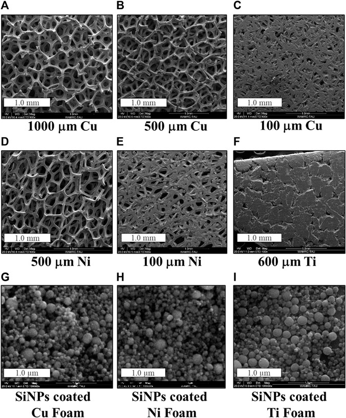
The initial thickness of the purchased copper foam was 1 mm, which was further reduced by calendaring to 500 μm and 100 μm. As shown in Figure 1, the calendaring of the 1,000 μm-thick foam to a 500 μm-thick foam is followed by a slight decrease in its porosity (Figures 1A, B). Calendaring to 100 μm thickness significantly reduces the porosity and the surface area of the foam, resulting in a more foil-like surface appearance (Figure 1C). Rough estimation suggests porosity reduction from 95.0% to 88.9% and 82.7%, respectively. The porosity of the nickel foam, which underwent calendaring, was reduced from 95.0% to 64.1% (Figures 1D, E). Because of the stiffness and low porosity (35%) of the 600 μm-thick titanium foam (Figure 1F) it was used as is. Figures 1G–I display exemplified SEM micrographs of Cu, Ni and Ti foams loaded with silicon nanoparticles (SiNPs) by electrophoretic deposition at 100 V for 60 s. At high magnification similar surface morphology is observed, with most SiNPs not exceeding a few tens nanometers in size. Silicon mass loading of the 3D-anodes varied from 1.03 to 1.66 mg. The difference in the mass loading has been reflected in the thickness variation of the electrophoretically deposited layer on top of the foams. There are several reasons that can influence this difference. Poor penetration of Si into the bulk has been particularly found for pressed foams. This may be attributed to the formation of silicon aggregates in the suspension, which block the pores of the foam and prevent migration of Si particles into the inner part of the foam, as found in (Xu et al., 2017). Formation of thin silicon deposit on titanium is presumably caused by high-resistant titanium oxide, incompletely removed by etching, thereby hindering the EPD process.
Upon annealing, transition metal atoms diffuse into silicon, creating metal-silicide. Diffusion coefficients of Cu, Ni and Ti in silicon at 1,100°C are 1 x 10⁻⁴, 4 x 10⁻⁵, and 6 x 10⁻¹¹ cm2/s, respectively, indicating that thermal penetration of copper in silicon is the fastest one (Weber, 1983; Chen and Liang, 2019). This is reflected in high-copper-content silicide as compared to those of nickel and titanium and was expected to enable higher electronic conductivity of the 3D anodes. According to silicon phase diagrams with transition metals, Cu3Si has two phases with different structures: below 467°C the η'' phase is formed, with an orthorhombic structure, and above 467°C Cu3Si forms η′ phase with a rhombohedral structure. Ni3Si2 structure is characterized by the orthorhombic unit cell. In TiSi2, the base-centered orthorhombic C49 TiSi2 phase forms first, after which the low-resistivity C54 TiSi2 (face-centered orthorhombic) is formed. Bearing in mind this information, Si-loaded copper samples were annealed at 350°C and 500°C. Si-loaded Ni samples were annealed at 950°C and Si-loaded Ti samples were annealed at 750°C (Olesinski and Abbaschian, 1986; Pretorius, 1996; Gambino and Colgan, 1998; Bhaskaran et al., 2007; Zhang et al., 2008; Riani et al., 2009; Sufryd et al., 2011; Huang et al., 2013; Dodony et al., 2019; Mados et al., 2021). As expected, the thinner is the foam and/or the smaller is the pore size after calendaring, the thicker is the deposited Si layer on the surface. This, in turn, results in larger content of pristine silicon particles, which are left unreacted with the metal at high temperature. As presented in Figures 2A, B, annealing of Si-Cu sample at 500°C makes the deposited layer more compact and homogeneous. Since the η'', which is formed first, is converted to the η′ phase (Samson et al., 1993) it can be suggested that after 2 h of annealing both phases are present, and increased annealing time is required for the full transformation of the η" phase to the η′ phase.
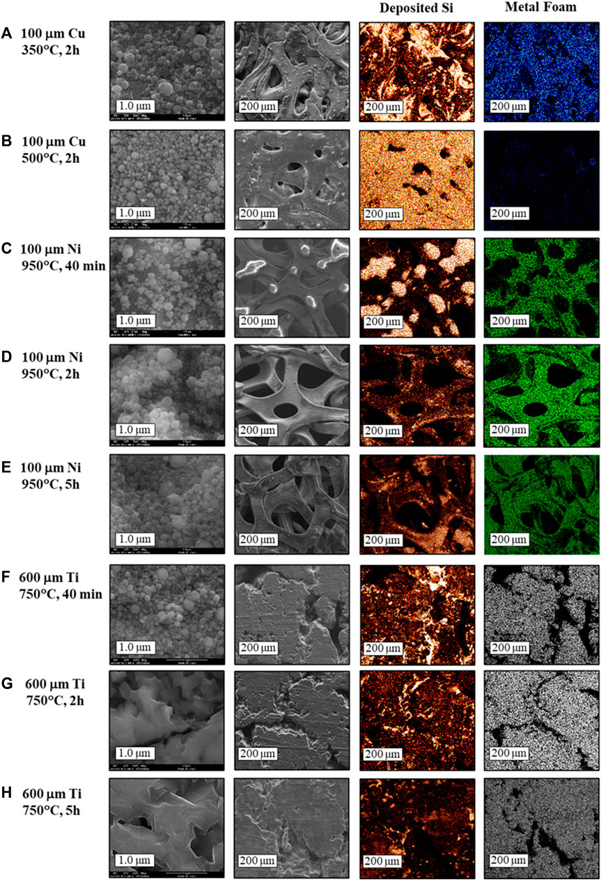
FIGURE 2. SEM micrographs and EDS mapping (red- deposited Si; blue, green and white- copper, nickel and titanium foams, respectively) of the annealed SiNPs-loaded foams.
Increase of the annealing duration is expected to promote formation of thicker metal silicide layers. As can be seen in Figure 2, the fine morphology of the outer silicon layer, unreacted with metal, is similar for Si-Ni and Si-Cu 3D-substrates annealed for 2 h. However, the low-magnification EDS maps show that upon annealing of Si-Ni sample for 40 min there is a clustering process of silicon nanoparticles at the outset. Silicon-poor voids between clusters are clearly seen in the element distribution maps (Figure 2C). These voids disappear with prolonged thermal treatment, indicating gradual formation of the Ni3Si2 layer. The fine surface morphology of silicon deposit on 600 μm-thick titanium foam annealed at 750°C for 40 min is preserved (Figure 2F), while prolonged annealing causes merging of individual nanoparticles (Figures 2G, H). Silicidation processes are known to occur in general via two mechanisms, which depend on the type of metal and the reaction between the metal and silicon. Silicon nanoparticles are easily oxidized even at room temperature and their surface is covered by an ultrathin “native” oxide with a thickness of about 1 nm. The first group of metals, such as Al, Ti, and Mg have thermodynamically favorable reaction products with SiO2. These metals easily decompose the SiO2 surface layer on the silicon particle. The neat silicon is then consumed for the silicide formation, and the O2 is dissolved in the metal to form a metal-oxide layer near the surface. This mechanism is homogeneous, as seen in the SEM images of the Si-Ti samples shown in Figure 2. The second mechanism involves the group of metals which do not have thermodynamically favorable reaction products with SiO2, such as Ni, Cu, W and Pt. This mechanism is diffusion-based and results in inhomogeneous growth of the silicides at the metal/silicon interface. The observed silicon-poor voids may be caused by SiO desorption from the surface, according to Eq 5:
This reaction is catalyzed by Ni, Cu and W atoms, which diffuse to the SiO2/Si interface and nucleate at the oxide defect or void. The diffusion occurs via bulk and through micro-voids of 10-20Å diameter, the latter is the predominant mechanism. Once the metal penetrates the Si/SiO2 interface, it reacts with silicon to form silicide. The energy released in this reaction speeds up the void formation. As more Si is consumed for enhanced growth of metal-silicide, void-filling process occurs through precipitate filling (Ting et al., 1984; Dallaporta et al., 1990; Aurongzeb et al., 2005; Li et al., 2010; Jung et al., 2012).
X-Ray Diffraction (XRD) was used to study the composition and structure of the silicon 3D on-foam anodes. The measurements were performed on 5 h-annealed samples, as enhanced annealing time enables the formation of thicker silicide layer. The chosen thicknesses were 100 μm for copper and nickel foams and 600 μm for titanium, with similar mass loading of SiNPs. As shown in the normalized XRD spectra (Figure 3), all samples present diffraction peaks assigned to Si at 2θ scattering angles of 28.6°, 47.3°, 56.1° and 76.4° (Kim et al., 2005; Yan et al., 2007; Lee et al., 2009; Zhang et al., 2019). Moreover, all samples present diffraction peaks attributed to the metal substrate, located at: 43.3°, 50.4°, 74.1° and 74.3° for copper (Kim et al., 2005; Ma et al., 2016), 44.5°, 51.8° and 76.3° for nickel (Yan et al., 2007; Zhang et al., 2008; Li et al., 2013), and 27.4°, 35.2°, 36.1°, 39.8°, 52.3°, 56.6°, and 69.8° for titanium (Mondal et al., 2014; Lee et al., 2016). In addition, all samples present clear Bragg lines associated with the MxSiy phases. For copper, the diffraction peaks are located at scattering angles of 43.4° and 50.6° and are attributed to Cu3Si (Kim et al., 2005; Ma et al., 2016; Zhang et al., 2019). As expected, the intensity of these peaks is higher for the sample annealed at 500°C than for the annealed at 350°C sample. However, in our tests we have not succeeded in distinguishing between the η" and η′ phases of copper silicide. For Si-Ni sample, the peaks detected at the scattering angles 44.5°, 44.7 and 51.9° have been attributed to the orthorhombic Ni3Si2 (Du et al., 2011; Li et al., 2013). For Si-Ti sample, the diffraction peaks assigned to TiSi2 are located at 2θ= 37.7°, 39.2°, 41.3°, 44.1° ad 68.9° (Roy et al., 1995; Lee et al., 2009). In all samples, the XRD analysis implies the existence of three layers: the bottom layer of metal foam; the top layer, which consists of neat unreacted silicon nanoparticles, and a metal-silicide layer which is formed in-between upon annealing.
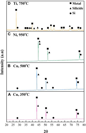
FIGURE 3. Normalized XRD diffractograms of the 5 h annealed Si-deposited foams: (A) Cu, 350°C, (B) Cu, 500°C, (C) Ni, 950°C and (D) Ti, 750°C.
The X-ray Photoelectron Spectroscopy measurements were performed on the 5-h-annealed samples (Figure 4), as those used for the XRD tests. Due to the thick layer of neat-SiNPs on their surface, the copper and nickel samples underwent sputtering at a rate of 47.6 Å/min (calibrated to SiO2) until the atomic % of copper and nickel significantly increased on behalf of the Si-XPS signal. Sputtering time was 1 minute for the copper samples and 6 minutes for the nickel sample. Despite the prolonged sputtering, reaching the depth of about 30 nm, the nickel-silicide layer could not be detected. We attribute this to the formation of thick silicon layer on the top of 3D-Ni-foam during EPD process, in agreement with (Xu et al., 2017), explained by poor penetration of SiNPs to the bulk of the foam. After sputtering, the Cu atomic percent increased from 0% to 3.7% and 21.5% for the copper samples annealed at 350°C and 500°C, respectively. This implies a thicker silicide layer for the latter, as expected. Due to the thin unreacted Si layer on the titanium foam, sputtering was not required to detect the silicide. Fitting of the XPS spectra shown in Figure 4, enabled assignment of the XPS peaks at 103.7 eV and 101 eV to SiOx and Si, respectively. The peaks at 98.8 eV and 99.4 eV are assigned to TiSi2 and Cu3Si, respectively, confirming the formation of a silicide layer between the metal and the neat silicon deposits (Yang et al., 1984; Banholzer and Burrell, 1986; Aarnink et al., 1990).
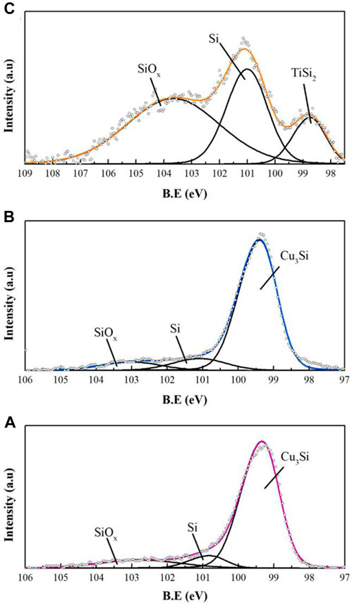
FIGURE 4. XPS Si 2p spectra of 5 h annealed Si-deposited foams: (A) Cu, 350°C, (B) Cu, 500°C, (C) Ti, 750°C.
Electrochemical tests
Pristine and annealed 100 μm-thick silicon-on-foam samples were tested as the anodes in Si/NMC cells. High-voltage NMC cathode is known as the most recent cutting-edge positive electrode for LIBs. It has low internal resistance coming from manganese, high capacity from nickel and the low content of cobalt in the lattice which enables lowering the cost of the cathode active material (Schmuch et al., 2018).
Figure 5 presents the cycle life of the NMC/Si cells with as-deposited 3D Si-on-Cu electrode (SiCu) and the anodes annealed at 350°C and 500°C for 40 mins and 2 h (Si-Cu3Si). NMC/SiCu cell with pristine anode displays an initial lithiation capacity of 2,641 mAh/gSi, the initial capacity of delithiation was 1,520 mAh/gSi, with an irreversible capacity (Qirr) of 42%. As shown in Figure 5, the discharge capacity completely fades at the 20th cycle. Since our anodes are binder-free, we suppose that such capacity decay stems from the loss of mechanical and electrical contacts of silicon nanoparticles with the current collector caused by the internal stresses occurring on charge/discharge. This, in addition, is followed by a continuous SEI formation on newly exposed surface of Si particles. The cell with Si-Cu3Si anode annealed at 350°C for 2 h presents a discharge capacity of ∼300 mAh/gSi+Silicide after 80 cycles, while the other copper-foam-based anodes show even lower capacity. As mentioned above, increasing annealing temperature from 350°C to 500°C results in a transition of the η" copper silicide phase to the η′ phase, . Annealing time of 2 h at 500°C results in worse performance compared to the sample annealed for 2 h at 350°C. When keeping in mind the similar Qirr and Faradaic efficiency (23% and 98.6%–99.4%, respectively, at prolonged cycling) we suggest that η" Cu3Si phase is beneficial for LIB.
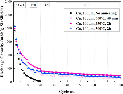
FIGURE 5. Cycle life of 100 μm thick 3D SiNPs-on-copper anodes pristine and annealed at 350°C and 500°C for 40 min and 2 h.
The cycle life of the cell with pristine and annealed silicon anode deposited on the nickel foam (NMC/SiNi, NMC/Si-Ni3Si2) is shown in Figure 6A. Until the 30th cycle the cell with the anode annealed for 40 min (∼0.7 h; 07SiNi) presented higher discharge capacity values than of the cell comprising SiNi anode annealed for 2 h (2SiNi). At the same time the Qirr of 07SiNi (7.2%) and long-term capacity loss/cycle (1.1%/cycle) were higher, than those of 2SiNi (4.8% and 0.8%/cycle, respectively). We assign lower capacity retention of the 40 min annealed Si-Ni3Si2 anode to the thicker layer of neat, unreacted silicon nanoparticles on top of thinner layer of Ni-silicide. Good long-term stability of Si-Ni3Si2 anode annealed for 2 hours, which exhibits 520 mAh/gSi+Silicide after 80 cycles can be explained, in addition, to high reversibility of lithiation of nickel silicide layer, in agreement with (Liu et al., 2007).
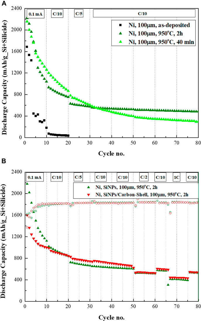
FIGURE 6. (A) Cycle life of 100 μm thick 3D SiNPs-on-nickel anodes pristine and annealed at 950°C for 40 min and 2 h. (B) Cycle life of annealed 3D SiNPs-on-nickel anodes with and without carbon coating.
As described in the literature (Schneier et al., 2019), one of the ways to improve the electrical conductivity of Si-anodes is carbon coating of the particles. In our tests the sample of silicon electrophoretically deposited on nickel foam was wetted with sucrose solution as carbon precursor and annealed at 950°C for 2 h. Energy dispersive X-ray spectrometer analysis of the sample detected 38.04 at % of carbon, formed by pyrolysis of sucrose, 15.54 at% of Si and 46.41 at% of nickel. The morphology of this sample was very similar to that prepared without carbon coating. As presented in Figure 6B the initial discharge capacity of the Si-Ni3Si2-C anode is 1600 mAh/gSi+Silicide, lower than the initial discharge capacity obtained for the anode prepared without the carbon-coating—2,180 mAh/gSi+Silicide. This difference may be caused by the formation of silicon and nickel carbides during pyrolysis, which are known to be inactive anode materials (Sri Devi Kumari et al., 2013; Huang et al., 2018). During the first 50 cycles, the Si-Ni3Si2-C anode displays lower capacity loss per cycle, presumably accompanied by better accommodation of volumetric expansion of silicon nanoparticles on the top of nickel silicide layer. In addition, the carbon-reinforced anode presents higher capacity values over cycles #20–50 at C/5 and C/10 rates. Increasing the C-rate from C/10 to C/2 after 50 cycles, results in a similar capacity value of ∼530 mAh/gSi+Silicide for both anodes. Good capacity retention is observed for both anodes, as well. Reducing the C-rate back to C/10 results in a slightly higher capacity for the carbon-reinforced anode–601 mAh/gSi+Silicide vs. 575 mAh/gSi+Silicide for the carbon-less one. The capacity retention rate is maintained. Increasing the C-rate from C/10 to 1C is followed by a capacity drop to 440 and 410 mAh/gSi+Silicide for the sample prepared with- and without-carbon coating, respectively. Decreasing the C-rate back to C/10 results in a capacity of ∼540 mAh/gSi+Silicide for both anodes. Silicon anodes deposited on titanium foam (SiTi) present a different trend, in which the discharge capacity decreases with enhanced annealing duration. Moreover, the capacity loss/cycle is the lowest for the sample annealed at 40 min (0.8%/cycle). Regarding Qirr and Coulombic efficiency, the 40 mins and 2 h annealed anodes present similar data (∼5% and 99% at cycle #80, respectively). We suggest that when initially a thin layer of silicon is electrophoretically deposited on the foam, prolonged annealing further thins out the neat silicon on top of the growing silicide layer. As found in (Lee et al., 2018), silicon-titanium core-shell particles show lower capacity, as compared to neat silicon. The authors (Schmuch et al., 2018) ascribe the origin of this phenomenon to the formation of titanium diffusion barrier, which limits lithiation of Si. However, in our case titanium does not envelope silicon nanoparticles. Based on higher Coulombic efficiency of Si-TiSi2 anode than that of neat Si anode and in accordance with the dilatometry and Raman data presented in (Lee et al., 2018), we believe that titanium silicide makes the volumetric changes in the composite anode more reversible and more stable.
The capacity retention of NMC/Si-TiSi2 cell (0.82%/cycle capacity loss) is better than of the NMC/Si-Ni3Si2 ones, as shown in Figure 7. Regarding the discharge capacity after 80 cycles, the Si-TiSi2 anode annealed at 2 h delivers 430 mAh/g_Si+Silicide. Silicon anodes deposited on 500 μm-thick copper and nickel foams and annealed for 2 h (not shown here) display discharge capacities of 305 and 236 mAh/g_Si+Silicide, respectively. However, overall, Si-Ni3Si2 anode on 100 μm-thick foam still outperforms by 20% that of Si-TiSi2 in terms of capacity value at cycle #80.
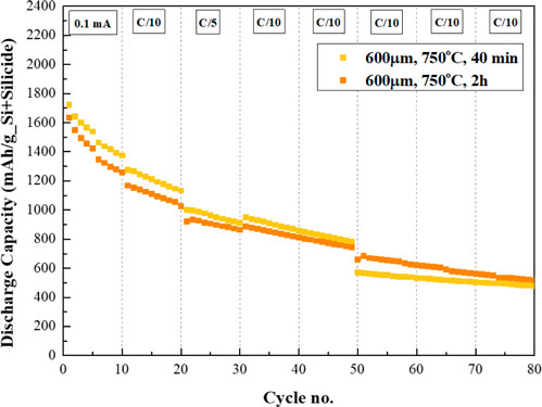
FIGURE 7. Cycle life of 600 μm thick 3D SiNPs-deposited titanium anodes annealed at 750°C for 40 min and 2 h.
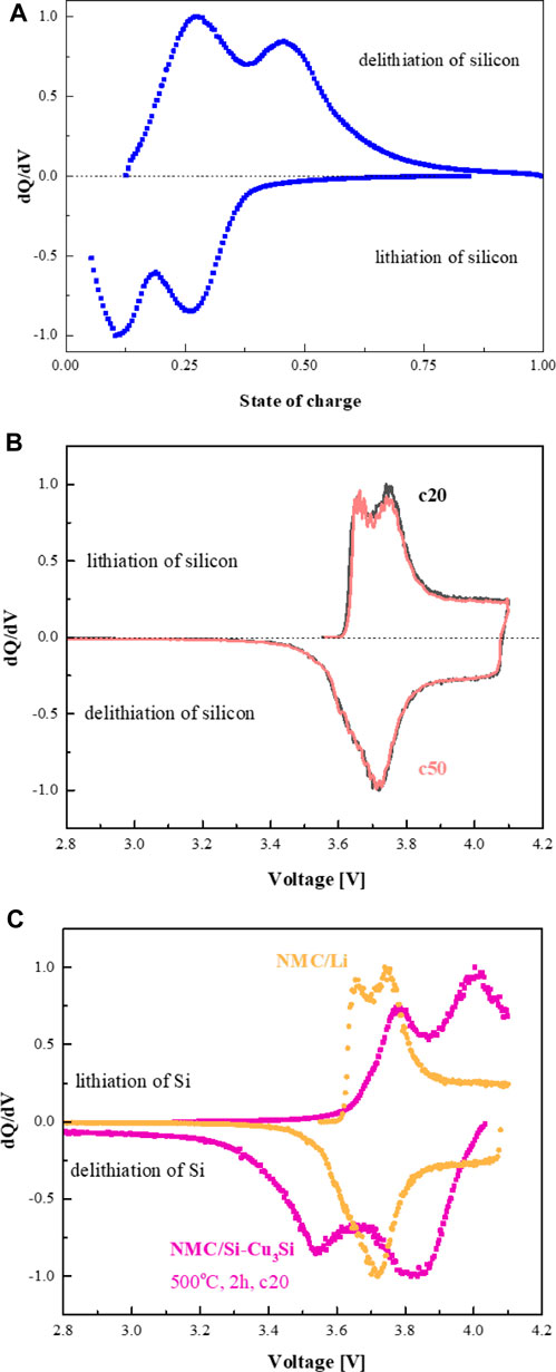
Differential capacity analysis (DCA) is a technique used to study the mechanisms of charge/discharge. The dQ/dV peaks correspond to phase transitions in the active electrode material arising from cation insertion/de-insertion or conversion reactions, from which the behavior of the cell can be understood (Berecibar et al., 2016; Fly and Chen, 2020). Figure 8A shows normalized dQ/dV plots for Si/Li cells with the binder-free silicon anode, presented by us in the previous publication (Mados et al., 2021). It is well established that on the first lithiation, crystalline silicon becomes amorphous (completely or partially), depending on the current density and voltage window). This happens at about 90 mV. During 100% DOD delithiation, on the second and subsequent cycles, typically two dQ/dV peaks are observed. The dQ/dV peak at about 450 mV corresponds to the transformation of the lithium-rich c-Li3.75Si phase and partially delithiated/more disordered (defective) c-Li3.75-δSi crystalline phase to amorphous lithium silicon alloy (a-Li∼1.1Si) (Ogata et al., 2014). The dQ/dV peak at about 270 mV is assigned to the delithiation of a-Li∼1.1Si. Two lithiation peaks, at about 100 and 250 mV, clearly visualized in the dQ/dV plots on cycling, are ascribed to the lithiation of large clusters of silicon, and to the conversion of amorphous lithium silicide to crystalline phases such as Li3.75Si, assisted by the formation of small clusters of silicon. These clusters may act as nuclei for the transformation of c-Li3.75Si/c-Li3.75-δSi into a-Li∼1.1Si on further cycling. The different overpotentials associated with the amorphous–crystalline lithium silicide conversions on discharge and charge are ascribed to the hysteresis of the charge/discharge reaction paths, caused by different kinetics (Ogata et al., 2014). found that it is much easier to add additional Li to c-Li3.75Si to form c-Li3.75+δSi than to remove Li from the structure. The defective structure formed on adding one Li atom to a supercell formed with two Li15Si4 unit cells, that is, Li3.875Si, has a lower formation energy than the structure formed by removal of Li, Li3.625Si.
NMC cathodes are known to present reversible nickel redox chemistry at ∼3.7 V. The role of cobalt is less clear, while manganese is maintained as Mn+4. As shown in Figure 8B, the dQ/dV charge plots of NMC-622 cathode vs. Li/Li+ are represented by 2 peaks at 3.66 V and 3.74 V, attributed to Ni+2 oxidation to Ni+3 and Ni+4. The broad dQ/dV discharge peak at 3.71 V with highly distinguishable shoulder is assigned to overlapped nickel reduction reactions. Upon cycling no significant shifts and redistribution of the relative intensity of the peaks was detected in agreement with the literature data (Shaju et al., 2002; Johnson, 2018; Mu et al., 2018; Ruan et al., 2018). The normalized dQ/dV plots of the NMC/Li and exemplified NMC/3D-Si-Cu3Si cell are shown in Figure 8C. The evolution of an additional peak at ∼3.9 V (charge) and ∼3.8 V (discharge) is detected in the plot of NMC/3D-Si-Cu3Si cell as compared to the plot of the NMC/Li cell. Besides, some broadening of the peaks associated with oxidation/reduction of nickel in the cathode is observed, suggesting their overlapping with the peak related to lithiation/delithiation of Si-based compounds. Bearing in mind the high stability of the NMC cathode upon prolonged cycling (Figure 8B), we assigned the major changes in the dQ/dV curves of the NMC/Si cell to those induced by the electrochemical behavior of the 3D-silicon anode.
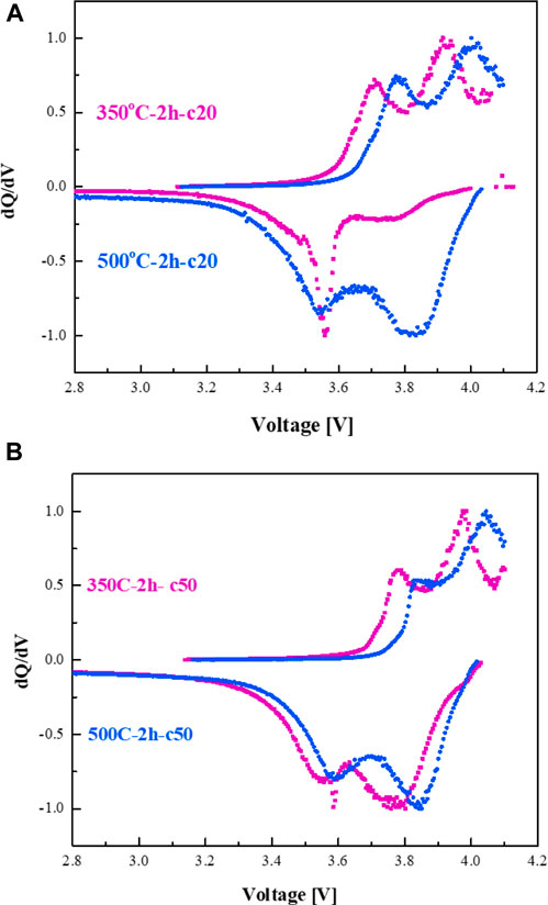
dQ/dV plots of NMC/3DSi-Cu3Si cells are presented in Figures 9A, B. We have found that prolonged annealing is followed by the increase in the peak areas that are associated with lithium-rich phase c-Li15Si4 (∼3.9 V- charge and ∼3.8 V- discharge) on behalf of the lithium-poor phase a-LixSi peak (∼3.5 V- charge and ∼3.4 V- discharge). This increase is more pronounced for the anodes annealed for 5 h. Short, 40 min annealing time causes formation of the insufficiently thick copper silicide layer. For the Si-Cu anode annealed at 350°C for 5 h, we suggest that a very thick silicide interlayer is formed, thus, less unreacted SiNPs are free to participate in the reversible electrochemical reactions, hence enabling high content of lithium-rich silicon phases. For the annealing temperature of 500°C, at which the η" phase is transformed into the η′ phase, the 2 h annealing time was found to be the optimal annealing duration. The presence of η" phase of copper silicide is reflected in faster kinetics of the lithiation/delithiation process as seen in the Figure 9. Upon prolonged cycling, the normalized dQ/dV plots show an increase in the intensity of the peaks associated with lithium-rich c-Li15Si4 phase.
The normalized dQ/dV plots of NMC/3D-Si-Ni3Si2 cells with the anodes annealed at 950°C for 40 min and 2 h are shown in Figures 10A, B. Both anodes present similar intensities of the peaks associated with the lithiated a-LixSi and c-Li15Si4 phases and smaller shifts of dQ/dV peaks upon prolonged cycling. This agrees with the enhanced capacity retention of the cell (Figure 6). The appearance of the dQ/dV peaks at ∼4 V can be assigned to Li plating/stripping on the bare nickel foam left in the bulk of the 3D current collector caused by the incomplete penetration of silicon nanoparticles during the EPD process.
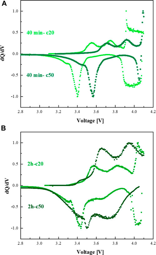
FIGURE 10. dQ/dV plots of NMC/3D Si-Ni3Si2 cells with the electrodes annealed at (A) 40 min and (B) 2 h.
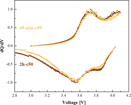
As mentioned above, the 3D-Si-TiSi2 anode differs from the silicon anodes deposited and annealed on copper and nickel foams. First, the deposited layer of silicon nanoparticles is thinner. Second, the mechanism of titanium silicide formation is a two-step process, in which titanium metal decomposes the silicon oxide SiO2 followed by the formation of TiSi2 and TiO2 near the surface (Ting et al., 1984; Yang et al., 1984; Dallaporta et al., 1990; Roy et al., 1995). We have found that increasing the annealing time results in the thickening of the mixed titanium silicide-titanium oxide layer, which causes lowering of the reversible discharge capacity, however it is still higher when compared to 3D-Si-on-Cu and 3D-Si-on-Ni anodes. This is reflected in stronger intensity of the dQ/dV peak associated with lithium-rich phase c-Li15Si4 (Figure 11).
Conclusion
3D Silicon/Silicide anodes were prepared by electrophoretically depositing silicon nanoparticles on copper, nickel, and titanium foams, followed by annealing at different temperatures. The metal silicides were obtained at temperatures of: 350°C (Cu3Si- η" phase) and 500°C (Cu3Si- η′ phase) for copper, 950°C for nickel (Ni3Si2) and 750°C for titanium (C54 phase- TiSi2).
XRD analysis implies the existence of three layers: the bottom layer of metal foam; the top layer which consists of neat-Si nanoparticles and a metal-silicide layer which is formed in between. XPS measurements confirm this structure, as well. In addition, from XPS and XRD measurements, it could be concluded that a thicker silicide layer on the copper anode annealed at 500°C was obtained as compared to the anode annealed at 350°C.
The 3D anodes on copper foam exhibit low reversible capacity, which may be attributed to poor adhesion of silicon to the current collector. Cu3Si- η" phase intermediate layer provides better performance than Cu3Si-η′ silicide. Due to the thick layer of silicon nanoparticles electrophoretically deposited on the surface of nickel foam, it was shown that enhanced annealing time is required for higher capacity and stability of the NMC cells with 3D SiNi anode. The 3D SiTi anodes presented a different trend than the copper and nickel anodes, in which the discharge capacity decreases with annealing time. The anode annealed for 40 min displayed a discharge capacity value of ∼500 mAh/g_Si+Silicide after 80 cycles, and the sample annealed for 2 h presented a capacity value of ∼400 mAh/gSi+Silicide after 80 cycles.
Based on the analysis of the structure and electrochemical properties of the 3D-on foam anodes the enhanced electrochemical performance of SiNi and SiTi composites can be attributed to the introduced Ni3Si2 and TiSi2 phases which act as good binding layers of silicon nanoparticles to the current collector, improving the structural stability and the electrical conductivity of the material. We believe that both nickel and titanium silicides are not the spectator phases, but undergo reversible lithiation, ultimately leading to better cycle performance. Careful study is essential to understand the complex interplay between the porosity, tortuosity, the thickness of foam and the loading of active material for 3D-electrode designs. The optimization of the thickness of the interfacial silicide layer to suppress the formation of the crystalline Li-rich silicon phase during lithiation for further stabilization of the electrode is under way and will be published elsewhere.
Data availability statement
The raw data supporting the conclusion of this article will be made available by the authors, without undue reservation.
Author contributions
SC: Data curation, Investigation, Validation, Visualization, Writing–original draft. DG: Conceptualization, Methodology, Resources, Supervision, Writing–review and editing.
Funding
The author(s) declare financial support was received for the research, authorship, and/or publication of this article. This work was partially supported by the Gordon Energy Fund of Tel Aviv University. The idea of testing copper foam as the current collector for binder-free silicon anodes came to the authors after discussion with Addionics Ltd. researchers.
Acknowledgments
The authors wish to thank Dr. Pini Shekhter and Dr. David Levy from the NanoCenter of Tel Aviv University for the XPS and the XRD analysis.
Conflict of interest
The authors declare that the research was conducted in the absence of any commercial or financial relationships that could be construed as a potential conflict of interest.
Publisher’s note
All claims expressed in this article are solely those of the authors and do not necessarily represent those of their affiliated organizations, or those of the publisher, the editors and the reviewers. Any product that may be evaluated in this article, or claim that may be made by its manufacturer, is not guaranteed or endorsed by the publisher.
References
Aarnink, W. A. M., Weishaupt, A., and van Silfhout, A. (1990). Angle-resolved X-ray photoelectron spectroscopy (ARXPS) and a modified Levenberg-Marquardt fit procedure: a new combination for modeling thin layers. Appl. Surf. Sci. 45, 37–48. doi:10.1016/0169-4332(90)90018-u
Aminu, I. S., Geaney, H., Imtiaz, S., Adegoke, T. E., Kapuria, N., Collins, G. A., et al. (2020). A copper silicide nanofoam current collector for directly grown Si nanowire networks and their application as lithium-ion anodes. Adv. Funct. Mater. 30, 1–9. doi:10.1002/adfm.202003278
Aurongzeb, D., Patibandla, S., Holtz, M., and Temkin, H. (2005). Self-assembly of faceted Ni nanodots on Si(111). Appl. Phys. Lett. 86, 1–3. doi:10.1063/1.1880452
Banholzer, W. F., and Burrell, M. C. (1986). XPS, Auger study of Cu3Si and its reaction with oxygen. Surf. Sci. 176, 125–133. doi:10.1016/0039-6028(86)90167-6
Berecibar, M., Devriendt, F., Dubarry, M., Villarreal, I., Omar, N., Verbeke, W., et al. (2016). Online state of health estimation on NMC cells based on predictive analytics. J. Power Sources 320, 239–250. doi:10.1016/j.jpowsour.2016.04.109
Bhaskaran, M., Sriram, S., Short, K. T., Mitchell, D. R. G., Holland, A. S., and Reeves, G. K. (2007). Characterization of C54 titanium silicide thin films by spectroscopy, microscopy and diffraction. J. Phys. D. Appl. Phys. 40, 5213–5219. doi:10.1088/0022-3727/40/17/030
Chen, X., and Liang, C. (2019). Transition metal silicides: fundamentals, preparation and catalytic applications. Catal. Sci. Technol. 9, 4785–4820. doi:10.1039/c9cy00533a
Dallaporta, H., Liehr, M., and Lewis, J. E. (1990). Silicon dioxide defects induced by metal impurities. Phys. Rev. B 41, 5075–5083. doi:10.1103/physrevb.41.5075
Ding, B., Cai, Z., Ahsan, Z., Ma, Y., Zhang, S., Song, G., et al. (2021). A review of metal silicides for lithium-ion battery anode application. Acta Metall. Sin. Engl. Lett. 34, 291–308. doi:10.1007/s40195-020-01095-z
Dodony, E., Radnóczi, G. Z., and Dódony, I. (2019). Low temperature formation of copper rich silicides. Intermetallics 107, 108–115. doi:10.1016/j.intermet.2019.01.010
Domi, Y., Usui, H., Takaishi, R., and Sakaguchi, H. (2019). Lithiation and delithiation reactions of binary silicide electrodes in an ionic liquid electrolyte as novel anodes for lithium-ion batteries. ChemElectroChem 6, 581–589. doi:10.1002/celc.201801088
Du, N., Fan, X., Yu, J., Zhang, H., and Yang, D. (2011). Ni3Si2-Si nanowires on Ni foam as a high-performance anode of Li-ion batteries. Electrochem. Commun. 13, 1443–1446. doi:10.1016/j.elecom.2011.09.017
Fly, A., and Chen, R. (2020). Rate dependency of incremental capacity analysis (dQ/dV) as a diagnostic tool for lithium-ion batteries. J. Energy Storage 29, 101329. doi:10.1016/j.est.2020.101329
Gambino, J. P., and Colgan, E. G. (1998). Silicides and ohmic contacts. Mater. Chem. Phys. 52, 99–146. doi:10.1016/S0254-0584(98)80014-X
Guo, J., Pei, S., He, Z., Huang, L., Lu, T., Gong, J., et al. (2020). Novel porous Si–Cu3Si–Cu microsphere composites with excellent electrochemical lithium storage. Electrochimica Acta 348, 136334. doi:10.1016/j.electacta.2020.136334
Gyanprakash D, M., and Kumar Rastogi, C. (2023). Investigation of silicon nanoparticle size on specific capacity of Li-ion battery via electrochemical impedance spectroscopy. J. Electroanal. Chem. 931, 117176. doi:10.1016/j.jelechem.2023.117176
Huang, X., Pu, H., Chang, J., Cui, S., Hallac, P. B., Jiang, J., et al. (2013). Improved cyclic performance of si anodes for lithium-ion batteries by forming intermetallic interphases between si nanoparticles and metal microparticles. ACS Appl. Mater Interfaces 5, 11965–11970. doi:10.1021/am403718u
Huang, X. D., Zhang, F., Gan, X. F., Huang, Q. A., Yang, J. Z., Lai, P. T., et al. (2018). Electrochemical characteristics of amorphous silicon carbide film as a lithium-ion battery anode. RSC Adv. 8, 5189–5196. doi:10.1039/c7ra12463e
Johnson, C. S. (2018). Charging up lithium-ion battery cathodes. Joule 2, 373–375. doi:10.1016/j.joule.2018.02.020
Johnson, D. C., Mosby, J. M., Riha, S. C., and Prieto, A. L. (2010). Synthesis of copper silicide nanocrystallites embedded in silicon nanowires for enhanced transport properties. J. Mater Chem. 20, 1993. doi:10.1039/b919281f
Jung, S. J., Lutz, T., Bell, A. P., McCarthy, E. K., and Boland, J. J. (2012). Free-standing, single-crystal Cu3Si nanowires. Cryst. Growth & Des. 12, 3076–3081. doi:10.1021/cg300273d
Kim, I. C., Byun, D., Lee, S., and Lee, J. K. (2006). Electrochemical characteristics of copper silicide-coated graphite as an anode material of lithium secondary batteries. Electrochimica Acta 52, 1532–1537. doi:10.1016/j.electacta.2006.02.055
Kim, J. W., Ryu, J. H., Lee, K. T., and Oh, S. M. (2005). Improvement of silicon powder negative electrodes by copper electroless deposition for lithium secondary batteries. J. Power Sources 147, 227–233. doi:10.1016/j.jpowsour.2004.12.041
Kim, Y. M., Ahn, J., Yu, S. H., Chung, D. Y., Lee, K. J., Lee, J. K., et al. (2015). Titanium silicide coated porous silicon nanospheres as anode materials for lithium ion batteries. Electrochimica Acta 151, 256–262. doi:10.1016/j.electacta.2014.11.016
Kimura, Y., Domi, Y., Usui, H., and Sakaguchi, H. (2020). Lithiation and delithiation properties of silicide/si composite alloy electrodes prepared by rapid quenching method. Electrochemistry 88, 330–332. doi:10.5796/electrochemistry.20-00039
Lee, H.-B., Hsu, H.-C., Wu, S.-C., Hsu, S.-K., Wang, P.-H., and Ho, W.-F. (2016). Microstructure and characteristics of calcium phosphate layers on bioactive oxide surfaces of air-sintered titanium foams after immersion in simulated body fluid. Mater. (Basel) 9, 956. doi:10.3390/ma9120956
Lee, K. M., Lee, Y. S., Kim, Y. W., Sun, Y. K., and Lee, S. M. (2009). Electrochemical characterization of Ti-Si and Ti-Si-Al alloy anodes for Li-ion batteries produced by mechanical ball milling. J. Alloys Compd. 472, 461–465. doi:10.1016/j.jallcom.2008.04.102
Lee, P. K., Tahmasebi, M. H., Ran, S., Boles, S. T., and Yu, D. Y. W. (2018). Leveraging titanium to enable silicon anodes in lithium-ion batteries. Small 14, e1802051–e1802058. doi:10.1002/smll.201802051
Li, F., Yue, H., Wang, P., Yang, Z., Wang, D., Liu, D., et al. (2013). Synthesis of core-shell architectures of silicon coated on controllable grown Ni-silicide nanostructures and their lithium-ion battery application. CrystEngComm 15, 7298–7306. doi:10.1039/c3ce40651b
Li, S., Cai, H., Gan, C. L., Guo, J., Dong, Z., and Ma, J. (2010). Controlled synthesis of copper-silicide nanostructures. Cryst. Growth & Des. 10, 2983–2989. doi:10.1021/cg1000232
Liu, W.-R., Wu, N.-L., Shieh, D.-T., Wu, H. C., Yang, M. H., Korepp, C., et al. (2007). Synthesis and characterization of nanoporous NiSi-Si composite anode for lithium-ion batteries. J. Electrochem Soc. 154, A97. doi:10.1149/1.2402106
Liu, X. H., Zhong, L., Huang, S., Mao, S. X., Zhu, T., and Huang, J. Y. (2012). Size-dependent fracture of silicon nanoparticles during lithiation. ACS Nano 6, 1522–1531. doi:10.1021/nn204476h
Ma, W., Liu, X., Wang, X., Wang, Z., Zhang, R., Yuan, Z., et al. (2016). Crystalline Cu-silicide stabilizes the performance of a high capacity Si-based Li-ion battery anode. J. Mater Chem. A 4, 19140–19146. doi:10.1039/c6ta08740j
Mados, E., Harpak, N., Levi, G., Patolsky, F., Peled, E., and Golodnitsky, D. (2021). Synthesis and electrochemical performance of silicon-nanowire alloy anodes. RSC Adv. 11, 26586–26593. doi:10.1039/d1ra04703e
Mondal, D. P., Patel, M., Das, S., Jha, A., Jain, H., Gupta, G., et al. (2014). Titanium foam with coarser cell size and wide range of porosity using different types of evaporative space holders through powder metallurgy route. Mater. Des. 63, 89–99. doi:10.1016/j.matdes.2014.05.054
Mu, L., Yuan, Q., Tian, C., Wei, C., Zhang, K., Liu, J., et al. (2018). Propagation topography of redox phase transformations in heterogeneous layered oxide cathode materials. Nat. Commun. 9, 2810. doi:10.1038/s41467-018-05172-x
Ogata, K., Salager, E., Kerr, C. J., Fraser, A., Ducati, C., Morris, A., et al. (2014). Revealing lithium-silicide phase transformations in nano-structured silicon-based lithium ion batteries via in situ NMR spectroscopy. Nat. Commun. 5, 3217. doi:10.1038/ncomms4217
Olesinski, R. W., and Abbaschian, G. J. (1986). The Cu−Si (Copper-Silicon) system. Bull. Alloy Phase Diagrams 7, 170–178. doi:10.1007/bf02881559
Oumellal, Y., Delpuech, N., Mazouzi, D., Dupré, N., Gaubicher, J., Moreau, P., et al. (2011). The failure mechanism of nano-sized Si-based negative electrodes for lithium ion batteries. J. Mater Chem. 21, 6201–6208. doi:10.1039/c1jm10213c
Peled, E., Golodnitsky, D., and Ardel, G. (1997). Advanced model for solid electrolyte interphase electrodes in liquid and polymer electrolytes. J. Electrochem Soc. 144, L208–L210. doi:10.1149/1.1837858
Pretorius, R. (1996). Prediction of silicide formation and stability using heats of formation. Thin Solid Films 290-291 (291), 477–484. doi:10.1016/S0040-6090(96)09022-0
Ratynski, M., Hamankiewicz, B., Buchberger, D. A., and Czerwinski, A. (2020). Surface oxidation of nano-silicon as a method for cycle life enhancement of Li-ion active materials. Molecules 25, 4093. doi:10.3390/molecules25184093
Riani, P., Sufryd, K., and Cacciamani, G. (2009). About the Al-Cu-Si isothermal section at 500 °C and the stability of the ε-Cu15Si4 phase. Intermetallics 17, 154–164. doi:10.1016/j.intermet.2008.10.011
Roy, R. A., Clevenger, L. A., Cabral, C., Saenger, K. L., Brauer, S., Jordan-Sweet, J., et al. (1995). In situ x-ray diffraction analysis of the C49-C54 titanium silicide phase transformation in narrow lines. Appl. Phys. Lett. 66, 1732–1734. doi:10.1063/1.113349
Ruan, Y., Song, X., Fu, Y., Song, C., and Battaglia, V. (2018). Structural evolution and capacity degradation mechanism of LiNi0.6Mn0.2Co0.2O2 cathode materials. J. Power Sources 400, 539–548. doi:10.1016/j.jpowsour.2018.08.056
Sa, Q., and Wang, Y. (2012). Ni foam as the current collector for high capacity C-Si composite electrode. J. Power Sources 208, 46–51. doi:10.1016/j.jpowsour.2012.02.020
Samson, Y., Rousset, J. L., Bergeret, G., Tardy, B., Bertolini, J., and Laroze, G. (1993). On the surface segregation of silicon in Cu3Si. Appl. Surf. Sci. 72, 373–379. doi:10.1016/0169-4332(93)90375-L
Schmuch, R., Wagner, R., Hörpel, G., Placke, T., and Winter, M. (2018). Performance and cost of materials for lithium-based rechargeable automotive batteries. Nat. Energy 3, 267–278. doi:10.1038/s41560-018-0107-2
Schneier, D., Harpak, N., Menkin, S., Davidi, G., Goor, M., Mados, E., et al. (2020). Analysis of scale-up parameters in 3D silicon-nanowire lithium-battery anodes. J. Electrochem Soc. 167, 050511. doi:10.1149/1945-7111/ab6f5a
Schneier, D., Shaham, Y., Goldshtein, K., Goor, M., Golodnitsky, D., and Peled, E. (2019). Comparative characterization of silicon alloy anodes, containing single-wall or multi-wall carbon nanotubes. J. Electrochem Soc. 166, A740–A746. doi:10.1149/2.0761904jes
Shaju, K. M., Subba Rao, G. V., and Chowdari, B. V. R. (2002). Performance of layered Li(Ni1/3Co1/3Mn1/3)O2 as cathode for Li-ion batteries. Electrochim Acta 48, 141–151. doi:10.1016/S0013-4686(02)00593-5
Song, H., Wang, H. X., Lin, Z., Jiang, X., Yu, L., Xu, J., et al. (2016). Highly connected silicon-copper alloy mixture nanotubes as high-rate and durable anode materials for lithium-ion batteries. Adv. Funct. Mater. 26, 524–531. doi:10.1002/adfm.201504014
Song, Y., Schmitt, A. L., and Jin, S. (2007). Ultralong single-crystal metallic Ni2Si nanowires with low resistivity. Nano Lett. 7, 965–969. doi:10.1021/nl0630687
Sri Devi Kumari, T., Jeyakumar, D., and Prem Kumar, T. (2013). Nano silicon carbide: a new lithium-insertion anode material on the horizon. RSC Adv. 3, 15028–15034. doi:10.1039/c3ra40798e
Stokes, K., Geaney, H., Sheehan, M., Borsa, D., and Ryan, K. M. (2019). Copper silicide nanowires as hosts for amorphous Si deposition as a route to produce high capacity lithium-ion battery anodes. Nano Lett. 19, 8829–8835. doi:10.1021/acs.nanolett.9b03664
Sufryd, K., Ponweiser, N., Riani, P., Richter, K. W., and Cacciamani, G. (2011). Experimental investigation of the Cu-Si phase diagram at x(Cu)>0.72. Intermetallics 19, 1479–1488. doi:10.1016/j.intermet.2011.05.017
Ting, C. Y., Wittmer, M., Iyer, S. S., and Brodsky, S. B. (1984). INTERACTION BETWEEN Ti AND SiO//2. J. Electrochem. Soc. 131, 2934–2938. doi:10.1149/1.2115445
Um, J. H., Choi, M., Park, H., Cho, Y. H., Dunand, D. C., Choe, H., et al. (2016). 3D macroporous electrode and high-performance in lithium-ion batteries using SnO 2 coated on Cu foam. Sci. Rep. 6, 18626–18629. doi:10.1038/srep18626
Umirov, N., Seo, D. H., Kim, T., Kim, H. Y., and Kim, S. S. (2019). Microstructure and electrochemical properties of rapidly solidified Si–Ni alloys as anode for lithium-ion batteries. J. Industrial Eng. Chem. 71, 351–360. doi:10.1016/j.jiec.2018.11.046
Usui, H., Meabara, K., Nakai, K., and Sakaguchi, H. (2011). Anode properties of composite thick-film electrodes consisted of Si and various metal silicides. Int. J. Electrochem. Sci. 6, 2246–2254. doi:10.1016/s1452-3981(23)18181-8
Usui, H., Nomura, M., Nishino, H., Kusatsu, M., Murota, T., and Sakaguchi, H. (2014). Gadolinium silicide/silicon composite with excellent high-rate performance as lithium-ion battery anode. Mater. Lett. 130, 61–64. doi:10.1016/j.matlet.2014.05.065
Weber, E. R. (1983). Transition metals in silicon. Appl. Phys. A Solids Surfaces 30, 1–22. doi:10.1007/BF00617708
Wen, Z. S., Ji, S., Sun, J., Tian, F., Tian, R., and Xie, J. (2006) Mechanism of lithium insertion into NiSi2 anode material for lithium ion batteries. Rare Met. 25:77–81. doi:10.1016/S1001-0521(07)60049-7
Xu, K., He, Y., Ben, L., Li, H., and Huang, X. (2015). Enhanced electrochemical performance of Si-Cu-Ti thin films by surface covered with Cu3Si nanowires. J. Power Sources 281, 455–460. doi:10.1016/j.jpowsour.2015.02.023
Xu, Y., Li, J., and Huang, W. (2017). Porous graphene oxide prepared on nickel foam by electrophoretic deposition and thermal reduction as high-performance supercapacitor electrodes. Mater. (Basel) 10, 936. doi:10.3390/ma10080936
Yan, W., Li, H., Liu, J., and Guo, J. (2007). EPMA and XRD study on nickel metal thin film for temperature sensor. Sensors Actuators A Phys. 136, 212–215. doi:10.1016/j.sna.2006.11.012
Yang, W. Y., Iwakuro, H., Yagi, H., Kuroda, T., and Nakamura, S. (1984) Study of oxidation of TiSi2 thin film by XPS. Jpn. J. Appl. Phys. 23:1560–1567. doi:10.1143/JJAP.23.1560
Yang, Y., Chen, D., Liu, B., and Zhao, J. (2015). Binder-free Si nanoparticle electrode with 3D porous structure prepared by electrophoretic deposition for lithium-ion batteries. ACS Appl. Mater Interfaces 7, 7497–7504. doi:10.1021/acsami.5b00421
Yoshio, M., Tsumura, T., and Dimov, N. (2006). Silicon/graphite composites as an anode material for lithium ion batteries. J. Power Sources 163, 215–218. doi:10.1016/j.jpowsour.2005.12.078
Zhang, H., Xu, H., Lou, X., Jin, H., Zong, P., Li, S., et al. (2019). Micro-structured Si@Cu3Si@C ternary composite anodes for high-performance Li-ion batteries. Ionics (Kiel) 25, 4667–4673. doi:10.1007/s11581-019-03043-z
Zhang, H. L., Li, F., Liu, C., and Cheng, H. M. (2008). The facile synthesis of nickel silicide nanobelts and nanosheets and their application in electrochemical energy storage. Nanotechnology 19, 165606. doi:10.1088/0957-4484/19/16/165606
Zhao, C., Li, S., Luo, X., Li, B., Pan, W., and Wu, H. (2015). Integration of Si in a metal foam current collector for stable electrochemical cycling in Li-ion batteries. J. Mater Chem. A 3, 10114–10118. doi:10.1039/c5ta00786k
Keywords: binder free silicon anodes, Si nanoparticles, metallic foam current collector, metal silicide, electrophoretic deposition
Citation: Cherf S and Golodnitsky D (2023) Study of 3D binder-free silicide/silicon anodes for lithium-ion batteries. Front. Batteries Electrochem. 2:1292295. doi: 10.3389/fbael.2023.1292295
Received: 11 September 2023; Accepted: 25 October 2023;
Published: 14 November 2023.
Edited by:
Maria Forsyth, Deakin University, AustraliaReviewed by:
Neslihan Yuca, Istanbul Technical University, TürkiyeKevin Hays, Ionblox Inc., United States
Copyright © 2023 Cherf and Golodnitsky. This is an open-access article distributed under the terms of the Creative Commons Attribution License (CC BY). The use, distribution or reproduction in other forums is permitted, provided the original author(s) and the copyright owner(s) are credited and that the original publication in this journal is cited, in accordance with accepted academic practice. No use, distribution or reproduction is permitted which does not comply with these terms.
*Correspondence: Diana Golodnitsky, Z29sb2RAdGF1ZXgudGF1LmFjLmls
 Shiraz Cherf
 Diana Golodnitsky