 Zhuoying Yan
 Weiye Zhong
 Jia Ma2
- 1School of Physical Science and Technology, Guangxi University, Nanning, China
- 2Shanghai Astronomical Observatory, Chinese Academy of Sciences, Shanghai, China
- 3Key Laboratory of Radio Astronomy and Technology, Chinese Academy of Sciences, Beijing, China
- 4College of Sciences, Shanghai University, Shanghai, China
For the system noise temperature calibration of the K/Q/W triple-band cryogenic receiver on Tianma Radio Telescope (TMRT), a design of W-band eight-hole waveguide directional coupler is proposed in this paper. Based on the hole coupling principle proposed by Gian Guido Gentili, a simulation model of the eight-hole coupler is designed by ANSYS HFSS. Both simulation and experimental results demonstrate that the coupler exhibits excellent performance across the 80–110 GHz, with a coupling coefficient ranging from −25 dB to −26 dB, a directivity greater than 11 dB, and an isolation below −38 dB.
1 Introduction
Directional couplers (Lucci et al., 2006; Zheng et al., 2013; Rohlfs et al., 1998; Oraizi., 1998; Levy., 1968) are widely utilized passive microwave device that can be employed in microwave transmission systems for signal separation and isolation, as well as for coupling a portion of energy from the microwave transmission path to monitor microwave power. Four-port couplers, due to their directional coupling of energy, are commonly referred to as directional couplers. In the receiving system of a radio telescope, the directional coupler is strategically positioned between the feed horn and the 90° phase shifter, allowing external calibration noise signal to be injected into the receiving system simultaneously. This configuration facilitates real-time monitoring and accurate measurement of the system noise temperatutre.
According to the classification of transmission line structures, directional couplers can be categorized into microstrip couplers (Golaszewski and Abramowicz. 2017), coaxial couplers (McCurdy and Choi. 1999), and waveguide couplers (Zhang et al., 2013; Alessandri and Ravanelli., 1997). Microstrip couplers are more suitable for planar circuits.
Waveguide couplers, known for their robust structure, stable performance, and low noise, are also commonly used in radio telescope receiver systems. For instance, in 2009, Gentili et al. (2009) designed a new circular waveguide directional coupler for the K-band (19–26 GHz) cryogenic receiver on Sardinia Radio Telescope (SRT). This coupler features a rectangular waveguide that is divided into two sections by a circular waveguide, which are then recombined at the other end. Energy is coupled through four small holes at the microwave junction between the rectangular and circular waveguides. This circular waveguide design integrates seamlessly with the feed horn, effectively replacing the roles of two conventional rectangular couplers. By doing so, it not only streamlines the architecture of the receiving system but also reduces its overall complexity.
Currently, the design theory for directional couplers is more mature, with two main development directions: one is to enhance the flatness of the coupling level and directivity, and the other is to further widen the operational bandwidth at higher frequencies. In 2014, Yuan et al. (2014) designed a noise injection coupler in the Q-band (35–50 GHz) dual-beam cryogenic receiver on Tianma Radio Telescope (TMRT). This coupler is an improvement over the traditional circular waveguide coupler, with an average coupling of −31.5 dB and a flatness of less than 3 dB. In 2022, Ma et al. (2022) provided a theoretical basis for the eight-hole coupled circular waveguide directional coupler used in the K-band (18–26.5 GHz) receiver on TMRT based on the hole coupling theory of the interaction between circular waveguide and rectangular waveguide proposed by Gian Guido Gentili. This design effectively improved the coupler’s bandwidth and directivity without increasing its size.
Based on the hole coupling theory proposed by Gentili et al. (2009), an eight-hole circular waveguide coupler for the W-band cryogenic receiver on TMRT is proposed in this paper. This design not only increases the operational frequency but also widens the operational bandwidth while maintaining the excellent performance of the coupler. Within the frequency range of 80–110 GHz, the coupling level remains stable from −25 dB to −26 dB, the isolation is less than −38 dB, the directivity coefficient exceeds 11 dB, and the reflection coefficients at both the noise injection port and the signal output port are below −15 dB.
The second section of this paper introduces the energy coupling principle of the eight-hole directional coupler. Section 3 presents the structure, design parameters, and simulation results of the directional coupler. The measured results of the coupler are provided in Section 4, and finally, Section 5 concludes the paper.
2 Theory
The circular waveguide coupler proposed in this paper follows the small-hole coupling principle, where the circular waveguide splits the rectangular waveguide in the middle, creating small holes on their common wall. Electromagnetic waves enter the coupler from the rectangular waveguide and, after energy coupling through the small holes, are transmitted into the circular waveguide.
Both Bethe (1944) and Collin (1992) theorized that when an electromagnetic wave passes through a hole of much smaller than the wavelength, the field in the excitation region can be regarded as the superposition of two equivalent sources at the hole: an electric dipole
To design a more compact and higher-performance coupler, Gentili and others expanded and updated the small aperture coupling theory proposed by Bethe and Collin. Instead of using electric and magnetic dipoles as two equivalent sources, they employed current sources and magnetic current sources for analysis. Equations 3, 4 and Gentili et al. (2009) are equivalent analytical formulas.
After reasoning and calculations, when a unit wave
a is the long side of the rectangular waveguide, b is the short side, and
For a small hole with a certain wall thickness and a radius of
In Equation 15,
Based on this principle, Gentili designed a circular waveguide directional coupler operating in the frequency range of 19–26 GHz, and Ma et al. (2022) designed an eight-hole circular waveguide coupler operating in the 18–26.5 GHz band. The measured results demonstrated the accuracy of this principle. However, these two couplers do not meet the frequency requirements for the W-band receiver of the TMRT. Therefore, there is a need to propose a directional waveguide coupler that operates at a higher frequency and has a wider operational range.
3 Design of waveguide directional coupler
Single-hole couplers have certain limitations in use due to their poor coupling directivity and low coupling flatness. Based on the small-hole coupling theory, further research into multi-hole coupling is conducted to meet the high directivity and broadband requirements of the noise calibration system of radio astronomy receivers. This paper proposes an eight-hole circular waveguide directional coupler to enhance the observation efficiency of the W-band receiver for TMRT. This section discusses the design of an eight-hole circular waveguide directional coupler with a frequency range of 80–110 GHz. It exhibits good isolation, coupling, and directivity, as well as high flatness.
In this design, the circular waveguide splits the rectangular waveguide in the middle, as shown in Figure 1. One end of the rectangular waveguide is Port 1, where the calibration noise enters, and the other end is Port 2, which is connected to a matched load. The rectangular waveguide supports a single mode, with dimensions conforming to the WR-10 standard waveguide (a = 2.54 mm, b = 1.27 mm). The circular waveguide features two mutually orthogonal modes, H and V. Ports 3 and 4 are located at both ends of the circular waveguide, with Port 3 serving as the coupling port connected to the feed horn, and Port 4 serving as the isolation port, connected to the phase shifter at the backend.
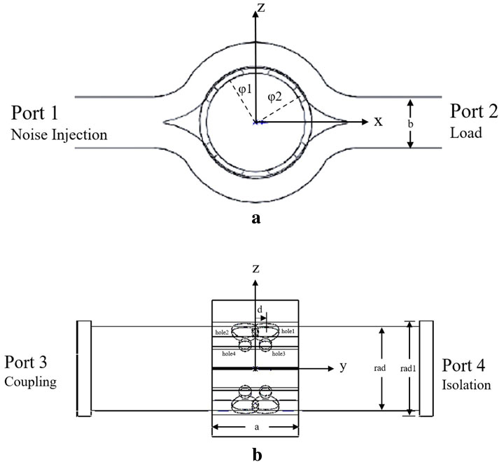
Figure 1. Structural diagram of the eight-hole coupler. (A) Front view. (B) Side view.
The noise enters the coupler through Port 1, which approximates the curved region around the circular waveguide as a rectangular waveguide and the wave is coupled into the circular waveguide through eight small holes. The holes are divided into two groups symmetrically about the Y-axis, which causes the horizontal polarization mode in the circular waveguide to be canceled out. Among these eight small holes, two sizes are used: the larger coupling hole has a radius of
The crosstalk between the two polarizations in the circular waveguide can affect the coupler’s coupling and directivity. After the continuous wave is coupled into the circular waveguide through the eight small holes, it can be divided into a forward wave A and a backward wave B along the axis of the circular waveguide. The position and size of the small holes affect the phase of the waves. When the wave travels from Port 1 to Port 4, if the wave coupled through the small holes has the same electrical length, the forward waves along the axis of the circular waveguide will be superimposed, while the backward waves will be canceled out. The expression for the directivity of this coupler is Equation 16.
The eight coupling holes are divided into two groups based on their aperture sizes for analysis. The coupling coefficient of the larger coupling holes, as well as their contribution to directivity and isolation, will be analyzed. From the ZOY plane, the larger coupling holes are symmetric along the Y-axis, and the coupling coefficients of the two holes in the positive Z-axis space are the same as those in the negative space. From Equations 5, 6, the expression for the coupling coefficient of the larger coupling holes is derived as follows:
In Equations 17, 18,
In the same way, Equation 21, 22 are the expressions for the coupling coefficients of small coupled holes.
where
According to the theory of small-hole coupling, the total coupling coefficient and isolation coefficient for V-polarization and H-polarization of the coupler are the sum of the contributions from the eight small holes, expressions such as Equation 25, 26.
To meet the requirements of the W-band receiver for TMRT, an electromagnetic model was established using the ANSYS HFSS, as shown in Figure 2.
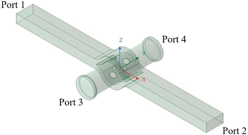
Figure 2. Electromagnetic simulation model of the coupler.
The key parameters of the eight-port waveguide directional coupler include the radius of the circular waveguide (rad), the radius of the transition section of the circular waveguide (rad1), the radius of the large coupling hole (hole_rad), the radius of the small coupling hole (hole_rad2), the angle (
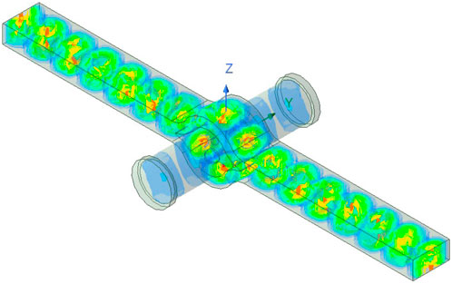
Figure 3. E field of the proposed circular waveguide directional coupler.
Figure 4 shows the effect of the coupling hole deflection angle (
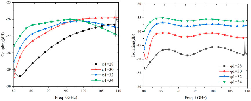
Figure 4. The effect of
As shown in the results of Figure 5, the size of the coupling aperture has a significant impact on both the coupling coefficient and the isolation coefficient, especially for the large coupling hole. As the coupling aperture increases, the coupling degree improves significantly, but the isolation deteriorates. Additionally, we need to consider that as the coupling aperture becomes larger, more electromagnetic waves can pass through the aperture, which enhances the coupling effect. This may lead to resonance at certain frequencies, resulting in a resonant phenomenon. It can be observed from Figure 5 that when the radius of the coupling hole increases to a certain value, the coupling deteriorates at low frequencies, and resonance occurs at specific frequency points. Therefore, it is necessary to comprehensively consider the size of the aperture to achieve high isolation and design requirements for coupling while avoiding resonance.
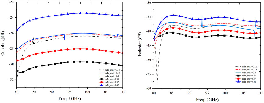
Figure 5. The effect of coupling hole radius on coupling and isolation.
Figure 6 shows that the effect of d on the coupling level of the coupler is minimal; however, an increase in d improves the isolation of the coupler.
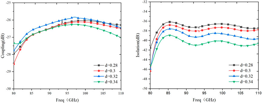
Figure 6. The effect of d on coupling and isolation of the coupler.
For the K/Q/W triple-band cryogenic receiver on TMRT, it is essential to maintain the injected noise level within approximately 10% of the system noise temperature. To meet the stringent requirements for noise calibration, the coupler specifications are critical. Specifically, the coupler must exhibit a coupling level of around −25 dB, provide isolation greater than −35 dB, and ensure directivity exceeding 10 dB. After simulation and analysis, the optimal parameter values are presented in Table 1, with WR-10 standard rectangular waveguide.
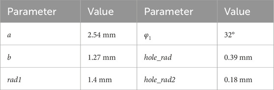
Table 1. Dimensions of the directional coupler.
Considering that the W-band operates at high frequencies, both the hole and waveguide dimensions are very small, requiring high precision in machining. Errors introduced by mechanical equipment, cutting tools, and cutting processes can potentially impact the performance of the directional coupler and may introduce resonances. Therefore, some tolerance space should be incorporated into the coupler’s design. Based on the error range provided by the manufacturer, all parameters were adjusted by
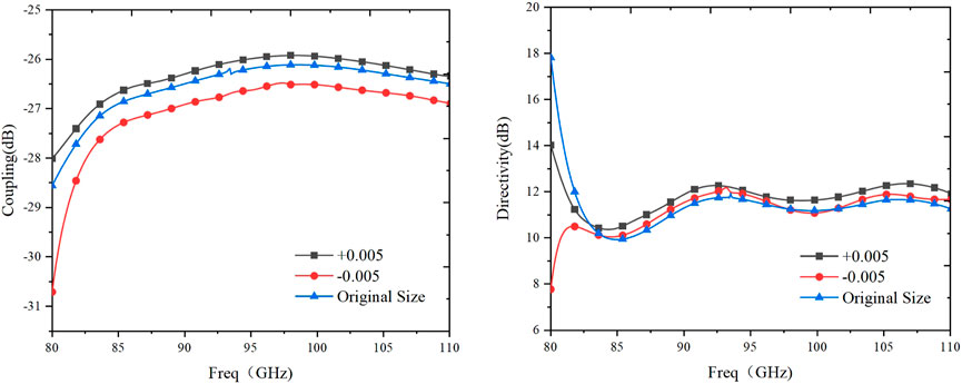
Figure 7. Tolerance analysis.
4 Measured results of the waveguide directional coupler
Based on the structural parameters of the simulation model, a prototype was fabricated using mechanical machining methods, with the material being AL6061-T6. The thermal expansion coefficient of this material is 23.9

Figure 8. Physical model of the coupler.

Figure 9. Performance measurement of the coupler.
The measurement was conducted using the Keysight N5242B VNA, enhanced with the N5293AX03 frequency extension module to extend the maximum measurable frequency to 110 GHz. The VNA is equipped with a WR-10 standard waveguide port. For the setup, the coupler interfaces with the VNA via a transition from a circular to a rectangular waveguide. Port 1 of the coupler is connected to Port 1 of the VNA, and Port 2 is terminated with a matched load. For coupling measurements, Port 4 of the coupler is connected to the feed horn, with a black body placed in front of the horn to serve as an absorptive termination. Port 3 of the coupler is linked to Port 2 of the VNA through a waveguide transition. For isolation measurements, the feed horn is connected to Port 3 of the coupler, and Port 4 of the coupler is connected to Port 2 of the VNA through a waveguide transition. The connection measurement diagram is shown in Figure 10.
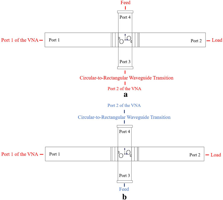
Figure 10. Measurement connection diagram. (A) Coupling measurements. (B) Isolation measurements.
Figure 11 shows that the measured results of the coupler are in good agreement with the simulation results, and the coupling degree meets the design requirements. Figure 12 shows the entire measured results of the eight-port directional coupler. In the measurement bandwidth of 80–110 GHz, the coupling level reaches −25 dB to −26 dB, and the coupling flatness is ±0.5 dB, showing good coupling flatness. The isolation is less than −38 dB, and the directivity coefficient is greater than 11 dB.
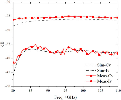
Figure 11. Comparison of isolation and coupling level simulation and measured results: coupling Cv; isolation Iv.
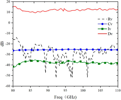
Figure 12. Coupler performance measured results: reflection coefficient Rv; coupling Cv; directivity Dv; isolation Iv.
The reflection coefficient at the noise injection port stays below −15 dB across the entire frequency band, as shown in Figure 13A. In contrast, the reflection coefficient at the signal output port experiences a slight rise at lower frequencies but remains below −20 dB above 82 GHz, as depicted in Figure 13B. Moreover, the measured insertion loss within the operational frequency range is less than 0.2 dB, as presented in Figure 14.

Figure 13. Reflection coefficient. (A) Noise injection port. (B) Signal output port.
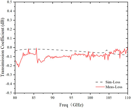
Figure 14. Insertion loss.
Table 2 presents a performance comparison of the coupler with similar structures from other studies. The results indicate that the coupler designed in this paper can operate at higher frequencies, with superior performance and high flatness. Table 3 compares the performance of couplers with different structures within the same frequency range. The coupler proposed in this paper not only operates stably over a wide frequency range but also demonstrates excellent performance in terms of coupling and isolation.
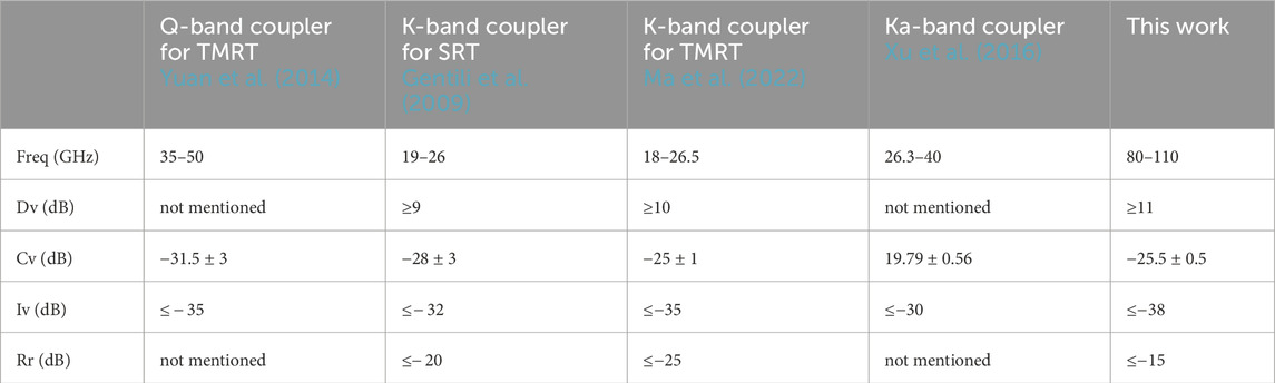
Table 2. Performance comparison of some recently reported directional couplers.
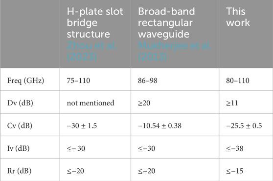
Table 3. Performance comparison of some recently reported directional couplers.
5 Conclusion
This paper presents an eight-hole circular waveguide directional coupler operating at the W-band, which is used as a noise injection coupler in the W-band receiver on TMRT. Simulation and measured results demonstrate that the eight-hole directional coupler exhibits good directivity, isolation, and coupling, with all three coefficients remaining very flat. Theoretically, changes in the shape of the coupling holes will directly affect the performance of the coupler. The symmetry of the circular hole gives the coupler a relatively uniform degree of coupling in all directions. However, when the shape of the coupling hole changes to an imperfectly symmetrical shape such as a cross or an oval, the coupling along the major axis is stronger, while the coupling along the minor axis is weaker. This change in directionality can be used to enhance or suppress signal coupling in specific directions, which requires further experimental verification.
Data availability statement
The original contributions presented in the study are included in the article/supplementary material, further inquiries can be directed to the corresponding author.
Author contributions
ZY: Writing–original draft. WZ: Writing–review and editing. JM: Writing–review and editing. HZ: Writing–review and editing. CZ: Writing–review and editing. ZP: Writing–review and editing. JW: Writing–review and editing.
Funding
The author(s) declare that financial support was received for the research, authorship, and/or publication of this article. The development of the K/Q/W triple-band cryogenic receiver on Tianma Radio Telescope (TMRT).
Conflict of interest
The authors declare that the research was conducted in the absence of any commercial or financial relationships that could be construed as a potential conflict of interest.
Generative AI statement
The author(s) declare that no Generative AI was used in the creation of this manuscript.
Publisher’s note
All claims expressed in this article are solely those of the authors and do not necessarily represent those of their affiliated organizations, or those of the publisher, the editors and the reviewers. Any product that may be evaluated in this article, or claim that may be made by its manufacturer, is not guaranteed or endorsed by the publisher.
References
Alessandri, F., and Ravanelli, R. (1997). A new class of dual-mode directional couplers for compact dual-polarization beam-forming networks. IEEE Microw. Guid. Wave Lett. 7, 300–301. doi:10.1109/75.622548
Bethe, H. A. (1944). Theory of diffraction by small holes. Phys. Rev. 66, 163–182. doi:10.1103/physrev.66.163
Gentili, G. G., Lucci, L., Nesti, R., Pelosi, G., and Selleri, S. (2009). A novel design for a circular waveguide directional coupler. IEEE Trans. Microw. Theory Tech. 57, 1840–1849. doi:10.1109/TMTT.2009.2022886
Golaszewski, A., and Abramowicz, A. (2017). Properties of high directivity microstrip couplers, 1–4.
Levy, R. (1968). Analysis and synthesis of waveguide multiaperture directional couplers. IEEE Trans. Microw. Theory Tech. 16, 995–1006. doi:10.1109/TMTT.1968.1126855
Lucci, L., Nesti, R., Pelosi, G., Selleri, S., and Tofani, G. (2006). “Design of a circular waveguide directional coupler at 22ghz,” in 2006 IEEE antennas and propagation society international symposium, 3443–3446. doi:10.1109/APS.2006.1711356
Ma, J., Zhong, W., Zhang, H., Zhang, C., Xu, Z., Sun, Z., et al. (2022). A highly directional eight-hole coupling circular waveguide coupler. Int. J. RF Microw. Computer-Aided Eng. 32. doi:10.1002/mmce.23208
McCurdy, A., and Choi, J. (1999). Design and analysis of a coaxial coupler for a 35-ghz gyroklystron amplifier. IEEE Trans. Microw. Theory Tech. 47, 164–175. doi:10.1109/22.744291
Mcdonald, N. A. (1972). Electric and magnetic coupling through small apertures in shield walls of any thickness. IEEE Trans. Microw. Theory Tech. 20, 689–695. doi:10.1109/tmtt.1972.1127844
Mukherjee, S., Sarkar, M., Bhanja, S., and Majumder, A. (2013). “Computer aided design of broad-band rectangular waveguide directional coupler at w band,” in 2013 IEEE applied electromagnetics conference (AEMC), 1–2. doi:10.1109/AEMC.2013.7045089
Oraizi, H. (1998). Optimum design of multihole directional couplers with arbitrary aperture spacing. Microw. Theory Tech. IEEE Trans.46, 331–342. doi:10.1109/22.664134
Rohlfs, K., Wilson, T. L., Burke, B. F., Graham-Smith, F., and Heiles, C. (1998). Tools of radio Astronomy and an Introduction to radio Astronomy. Phys. Today 51, 62–64. doi:10.1063/1.882299
Xu, K., Wang, Z., Yan, B., and Deng, X. (2016). Compact full ka-band waveguide directional coupler based on large aperture array. Electron. Lett. 52, 936–937. doi:10.1049/el.2016.0272
Yuan, T., Yin, X., Zhao, H., Shi, J., Zhong, W., and Liu, Q. (2014). “A design of q-band noise injector,” in Proceedings of 2014 3rd asia-pacific conference on antennas and propagation, 1162–1164. doi:10.1109/APCAP.2014.6992719
Zhang, Y., Wang, Q., and Ding, J. (2013). A cross-guide waveguide directional coupler with high directivity and broad bandwidth. IEEE Microw. Wirel. Components Lett. 23, 581–583. doi:10.1109/LMWC.2013.2281407
Zheng, P., Sun, H.-J., Luo, M.-J., Wen, Z.-L., and Deng, H. (2013). “W-band waveguide 3db directional coupler based on e-plane branch line bridge,” in 2013 asia-pacific microwave conference proceedings (APMC), 279–281. doi:10.1109/APMC.2013.6695119
Keywords: W-band, directional coupler, circular hole coupling, eight-hole coupling, broadband directional coupler
Citation: Yan Z, Zhong W, Ma J, Zhang H, Zhang C, Pu Z and Wang J (2025) Design of an eight-hole directional coupler for W-band cryogenic receivers. Front. Astron. Space Sci. 12:1538558. doi: 10.3389/fspas.2025.1538558
Received: 03 December 2024; Accepted: 21 January 2025;
Published: 14 March 2025.
Edited by:
Christophe Risacher, International Research Institute for Radio Astronomy, FranceReviewed by:
Ningfeng Bai, Southeast University, ChinaJuan Pablo Pascual, University of Cantabria, Spain
Copyright © 2025 Yan, Zhong, Ma, Zhang, Zhang, Pu and Wang. This is an open-access article distributed under the terms of the Creative Commons Attribution License (CC BY). The use, distribution or reproduction in other forums is permitted, provided the original author(s) and the copyright owner(s) are credited and that the original publication in this journal is cited, in accordance with accepted academic practice. No use, distribution or reproduction is permitted which does not comply with these terms.
*Correspondence: Weiye Zhong, d3l6aG9uZ0BzaGFvLmFjLmNu