 Honglan Fu
 Ming Wang
 Hao Zhang1*
95% of researchers rate our articles as excellent or good
Learn more about the work of our research integrity team to safeguard the quality of each article we publish.
Find out more
ORIGINAL RESEARCH article
Front. Astron. Space Sci. , 04 May 2023
Sec. Planetary Science
Volume 10 - 2023 | https://doi.org/10.3389/fspas.2023.1177573
This article is part of the Research Topic Recent Progress from Lunar, Mars and Asteroid Missions View all 5 articles
The cis-lunar periodic orbit exhibits some unique dynamic characteristics. Among them is the distant retrograde orbit, which has long-term stability and is one of the ideal candidate deployment orbits for cis-lunar space stations and deep-space exploration transfer stations. Orbiting, rendezvous, and docking are among the flight operations involved in space station on-orbit construction, material supply, spacecraft monitoring, and other tasks. Suitable initial conditions can be created for these operations by shortening the relative distance between spacecraft through phasing. In this study, the characteristics of a two-impulse phasing orbit on a distant retrograde orbit (DRO) are summarized, and its phasing ability is globally analyzed. Based on these analyses, a phasing optimization problem was presented and solved. Using DRO’s dynamic characteristics, a DRO multi-impulse phasing rolling solution method is presented. For accuracy purposes, the orbit determination error is also considered in this method. The simulation analysis was performed using the circular restricted three-body problem (CR3BP) dynamic model and the ephemeris model. Compared with the results of two-impulse phasing, this method reduces the offset of the end position of the DRO phasing orbit from hundreds to tens of kilometers. This result satisfies the relative distance requirements for subsequent spacecraft operations. The total pulse requirement of this phasing method for the two models was within a reasonable and feasible range.
With the development of astronautical technology and willingness of various countries to develop cis-lunar space resources, cis-lunar space utilization has increasingly attracted attention. In 2018, Queqiao, the relay satellite of the Chinese Chang’e-4, was launched successfully and injected into cis-lunar L2 orbit. This satellite was used to provide relay communication services for the Chang’e-4 landing on the far side of the Moon. Queqiao is the first special relay communication satellite outside the Earth’s orbit (Gao et al., 2019). NASA’s Artemis program plans to deploy lunar space stations, named LOP-G, around the Moon in 2024. Compared with near-Earth space stations, Earth-Moon space stations have many incomparable advantages. Research, including planetary science, astrophysics, Earth observation, solar physics, basic space biology, human health, and behavior, will be conducted using LOP-G (Fuller et al., 2021). The Lunar Pathfinder was developed by the Surrey Satellite Technology (Giordano et al., 2021). It was the first commercial lunar orbiter to provide high-performance, competitively priced Earth-Moon communication services. After the success of this mission, more lunar satellites will be launched to form a lunar GPS.
The cis-lunar periodic orbits exhibit unique dynamic characteristics. Distant retrograde orbits (DROs) have long-term stability (Bezrouk and Parker, 2014). This implies that the spacecraft deployed on a DRO requires only a small number of pulses for orbit maintenance. In addition, the DRO’s orbit amplitude is large; therefore, the entire cis-lunar space is visible to this orbit (Peng et al., 2018). Hence, the DRO is suitable as the parking orbit of a cis-lunar space station or deep-space exploration transfer station. Research on DRO applications has also been conducted. Murakami and Yamanaka (2015) introduced a DRO rendezvous program from two perspectives: orbit and launch window design. NASA proposed an asteroid redirect mission (Gates et al., 2015a; Gates et al., 2015b) that captures the asteroid and saves it on the DRO; subsequently, manned spacecraft from low-Earth orbit rendezvous with asteroids to carry out related scientific missions. Smitherman and Griffin (2014) analyzed the concept of the habitation module in deep-space exploration. The deployment of the habitation module on the DRO can support lunar missions, extend the duration of manned missions, and provide full lunar surface accessibility.
Spacecraft rendezvous and docking not only play an important role in traditional space missions but also are one of the key technologies to perform cis-lunar space missions. For example, the flight processes of missions such as the cis-lunar space station on-orbit assembly (Liu et al., 2019), material supply, and spacecraft monitoring (Corpino and Stesina, 2020), all include rendezvous and docking. Rendezvous and docking technologies have achieved extensive theoretical research and practical verification results in two-body space environments such as international space station missions in LEO and Apollo missions in LLO. However, research on cis-lunar three-body environments has only emerged in the last decade. The applications of natural dynamical structures of periodic orbits have been widely discussed. McCarthy and Howell (2021) investigated applications in eclipse avoidance and transfer design by utilizing quasi-periodic orbits and their related hyperbolic manifolds in the lunar region. Bolliger (2019) examined transfers between the Near-Rectilinear Halo Orbit (NRHO), and periodic orbits termed the “butterfly” family. Invariant manifolds of periodic orbits were used to design transfers in cislunar space, such as transfers from a super-Geostationary Transfer Orbit (sGTO) to NRHOs (Singh et al., 2021a; Singh et al., 2021c), and a Lunar Polar Orbit (Singh et al., 2021b). For a far-range rendezvous, Murakami et al. (2015) and Schulte et al. (2020) studied the impulsive maneuver method, and Lizy-Destrez et al. (2019) studied the manifold splicing method. Blazquez et al. (2018) and Blazquez et al. (2020) proposed that the natural drift of ephemeris NRHO relative to the reference orbit can be used to achieve far-range rendezvous and docking.
In the rendezvous stage, the navigation mode of the spacecraft changes from absolute navigation, which depends on the ground station, to relative navigation, which depends on the radar and optical cameras on board. Relative navigation has certain requirements regarding the relative distance between two spacecraft. Considering this requirement, a natural question is how to create suitable initial relative distance conditions for the DRO’s rendezvous and docking. Phasing can solve this problem. The latter can be classified into two patterns: phasing in the same orbit (Bucchioni and Innocenti, 2021) and phasing in different orbits (Sato et al., 2015; Chen and Ma, 2017; Qi and de Ruiter, 2020). The second one refers to a spacecraft departing from another orbit to its target phase on which the target spacecraft parks. Phasing in the same orbit indicates that the spacecraft is in the same orbit before phasing. If the phase in which the spacecraft enters after orbit transfer is not accurate, the final phase of phasing on different orbits is not suitable, or the rendezvous operation fails, the phasing on the same orbit needs to be performed again, which highlights the importance of the co-orbit phasing technology. In recent years, co-orbit phasing on the three-body periodic orbit around the cis-lunar space has been studied. To address the need for halo orbit navigation satellite deployment and on-orbit fuel refueling, Qi and de Ruiter (2020) analyzed two-impulse phasing on the halo orbit. For the maximum impulse maneuver constraint, a two-impulse phasing orbit optimization problem was proposed to achieve a maximum phase change., A frog-leaping phasing strategy is proposed when the phase difference changes significantly. This strategy enables multiple revisits of the halo orbit and is therefore suitable for fueling tasks. Motivated by the positioning using the Earth-Moon Halo Orbit Experimental Beacons (PHOEBE) project, Chen and Ma (2017) studied a phasing method using the invariable manifolds of NRHO to deploy the CubeSat target configuration. Fossà et al. (2022) designed a three-impulse co-orbit phasing method that used unstable and stable manifolds. This method was compared with two-impulse transfer phasing from the Halo parking orbit to the NRHO. Therefore, it can be concluded that the phasing costs of these two methods are equivalent. Sato’s research results show that when the phase difference between spacecraft on a Halo orbit is large, phasing using an invariant manifold can save fuel (Sato et al., 2015). Few phasing studies have considered these errors. Davis et al. (2020) analyzed and found that in the case of solar radiation light pressure, navigation error, and maneuvering error, the practical orbit of the spacecraft deviates from the NRHO baseline orbit and enters the Earth’s shadow area. This destroys the eclipse-free nature of the baseline orbit. Phase control was added to the orbit maintenance algorithm to adjust the time required for the spacecraft to pass through the perilune. This improved algorithm ensures eclipse-free characteristics of the baseline orbit. In Davis’s study, the goal of the phase control was orbit maintenance, which requires small pulses.
Model predictive control (MPC) is an optimal control algorithm based on prediction models. The algorithm has been widely applied in fields such as petrochemical industries, electric power, aerospace, transportation, and robotics (Qin and Badgwell, 2003; Holkar and Waghmare, 2010; Mayne, 2014). The rolling horizon optimization and feedback correction included in MPC can effectively solve optimal control problems with multiple uncertain factors (Camacho and Alba, 2013). Rolling optimization has the same relative form of performance indicators at each sampling time, but the time interval included is different. Optimization is not completed at one time but is repeatedly performed online, which is the meaning of rolling. Due to the existence of uncertainties such as model errors and environmental disturbances, online repeated optimization strategies can be robust against these uncertain factors. This study is partially inspired by the strength of the rolling optimization strategy and proposes a multi-impulse phasing rolling solution method. This method continuously updates the control from the updated orbit state, thus reducing the impact of uncertain factors on the deviation of the phasing orbit’s terminal position. The difference is that rolling optimization has a finite optimization time domain at each sampling time, while the multi-pulse phasing rolling solution method includes the time domain from the current time to the terminal time.
The DRO have a wide application in the future. This was the demand-driven task in this study. Space missions around a DRO cannot be completed without phasing technology. This is the technical demand considered in this study. Based on these two requirements, it is considered that the tracking and target spacecrafts are both on the same DRO, and then the co-orbit phasing operation is emphatically studied. DRO does not have stable/unstable manifolds; therefore, the existing low-cost phasing scheme using manifolds is not applicable. Modeling, orbit determination, and maneuvering errors are inevitable; therefore, it is necessary to address these errors. This is the feasibility requirement of this study. In this study, the returnability of free trajectories departing from the DRO is summarized. The characteristics of the two-impulse phasing orbit in the DRO are summarized, and its phasing ability is globally analyzed. These analyses included the effects of the flight time, initial phase of the spacecraft, and phase difference on the total required impulse. The results showed that, bounded by one orbital period, the phasing impulse decreased rapidly and then decreased slowly with an increase in flight time. This indicates that the ability to reduce the phasing impulse by increasing flight time is limited. Given the time of flight, the adjustable range of the phase difference increases linearly with an increase in the maximum impulse constraint. Based on these analyses, an optimization problem for phasing was designed and solved. Considering the orbit determination error, a multi-impulse phasing rolling solution method was proposed. The simulation results demonstrate that this method can effectively reduce the accumulation of orbit errors. In addition to the ideal model, this method applies to the ephemeris model, which indicates that it has practical significance.
This study is divided into six sections. The first section introduces the background of phasing in the cis-lunar space and the research status of phasing in the DRO. The second introduces the dynamics model and reference DRO. A mathematical model of the phasing problem is presented in Section 3. The characteristics of the phasing orbit on the DRO are discussed in the fourth section. A phasing optimization problem is also presented and solved. Section five gives the multi-impulse phasing rolling solution method, simulation results, and analysis. The final section concludes this paper.
The earth-centered inertial (ECI) coordinate frame and Moon center rotation (MCR) frame are defined in this section. They are shown in Figure 1.
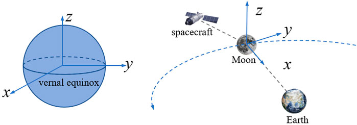
FIGURE 1. Earth-centered inertial frame and Moon-centered rotation frame.
The ECI is centered at the Earth’s center of mass. The Earth’s mean equatorial plane is the reference plane. The x-axis is aligned with a vernal equinox. The z-axis is aligned with the normal direction of the reference plane. The y-axis is perpendicular to the x- and z-axes, forming a right-handed Cartesian coordinate system.
The MCR is centered at the Moon’s center of mass. The x-axis points toward the center of mass of the Earth. The z-axis points in the direction of the angular momentum of the Moon with respect to the Earth. The y-, x-, and z-axes form a right-handed Cartesian coordinate system.
In the circular restricted three-body problem (CR3BP), it is assumed that the spacecraft is affected only by the gravity of the Earth and Moon, with masses mE, mM. The mass of the spacecraft is so small that it can be ignored. Furthermore, let us suppose that the two central bodies move in circles around a common centroid. In the frame MCR, the dimensionless dynamic equations of the spacecraft were obtained. The spacecraft state is written as
In which, μ = mM/(mE + mM) is the mass parameter of the earth-moon system, x, y, and z are the position components, res, rms present the distances between spacecraft, Earth, and Moon respectively:
In an Earth-centered inertial system, the dynamic equations of a spacecraft relative to the Earth are as follows:
where n is the number of celestial bodies of the solar system, μk is the mass parameter of the kth celestial body, subscript pk presents the kth celestial body, subscript e presents the Earth, and subscript i presents the spacecraft.
The DRO family is illustrated in Figure 2. Among these, a DRO with a period of approximately 14.7 days, equivalent to one-half of the Moon’s synodic period, is at a moderate distance from the Moon, making it easy to travel to the Moon, Earth, and even deep spaces. This orbit is denoted as a 2:1 lunar synodic resonant DRO, which indicates that two periods of this orbit are completed for one lunar synodic period. It is beneficial for mitigating long eclipses (McCarthy and Howell, 2021). Therefore, this orbit can be used as a parking orbit for the cis-lunar space station. This orbit was selected as the baseline orbit in this study.
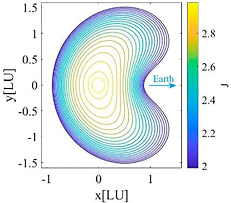
FIGURE 2. DRO family (Moon centered Moon–Earth rotation system).
The DRO’s phase is defined as follows.
where t0 is the time the DRO intersects the positive x-axis, and this intersection is the zero-phase point. t represents the moment at which the spacecraft travels along DRO to the phase θ. TDRO is the orbital period of the DRO.
The phase difference of spacecraft is given by
in which subscripts c and t represent chaser spacecraft and target spacecraft, respectively.
On DRO, the values of orbit state at time t are given by the mapping function of phase θ: x = g(θ).
We use the DRO trajectory under the CR3BP model as the initial guess; and construct a continuous four-loop counterpart (about 2 months) under the ephemeris model. The ephemeris-DRO still maintains the basic shape as that of the CR3BP-DRO. The orbital period of the ephemeris-DRO is defined as the averaged period. The DRO phase diagrams in the CR3BP and ephemeris models are shown in Figure 3. The initial epoch of the DRO in the ephemeris model was 2030/1/1 00:00:00. It is noteworthy to mention that the ephemeris DRO is not a closed orbit; therefore, the orbit states corresponding to the 0° and 360° phases are different.
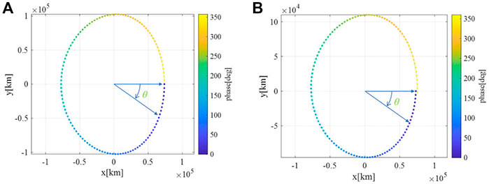
FIGURE 3. The definition of DRO (2:1) phase. (A) CR3BP model, (B) ephemeris model.
It is assumed that two spacecraft with an initial phase difference travel in the DRO. The chaser executes impulse several times, arriving at the same phase and time as the target spacecraft. This process is called multi-impulse DRO phasing. A general mathematical description of the multi-impulse phasing problem is presented in this section. Two-pulse phasing is a special case of multi-pulse phasing.
The initial phase angle of target is θt. The initial phase target of chaser is θc. The phase difference is Δθ = θc–θt. The orbit times corresponding to θt and θc are tt, and tc. The phase angle of rendezvous point is θr. The corresponding orbital time is tr. Because the target flies freely, the time of flight of phasing TOF can be determined by the phase parameters of the target:
Notably, the phase units in Eqs 4, 6 are radians. If the phase θ is in degrees, then the term “2π” in these two equations should be replaced by “360°”.
The number of impulses was assumed to be N. The phasing orbit is divided into N−1 arcs using N discrete points. The flight time was decomposed into N−1 segments. The departure and arrival times are t1 = tt and tN = tr. The corresponding times of the discrete points are
The multi-impulse phasing problem is stated as follows:
Given the phasing input parameters θc, θt (or Δθ), θr, find the departure pulse, the positions, and pulses of splicing points, so that the position constraints of splicing points and rendezvous point are satisfied.
Considering
where φ is a symbol of flow, which represents the orbit state obtained by integrating from an initial value for a time interval.
The multi-impulse phasing problem can be expressed using the formula in Table 1 (Zhao et al., 2016).
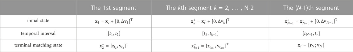
TABLE 1. Multi-impulse phasing model.
Constraints:
The unsolved variables consist of N pulses:
The two-impulse phasing problem is a special case of the multi-pulse phasing problem. When N = 2, the preceding equations represent a two-pulse phasing problem. The unsolved variables are Δv1, and Δv2.
The phasing orbit was close to the DRO baseline orbit, and the points in the DRO were chosen as the initial estimates for the patching points. The points on the two-pulse phasing orbit can also be chosen as the initial values when solving the multi-impulse phasing problem.
The phasing characteristics of the DRO were mainly analyzed from two aspects. First, the evolution characteristics of the free orbit from any point in the DRO are analyzed, and several definitions of returnability are provided. Subsequently, the characteristics of the DRO phasing orbit are studied using a two-impulse phasing method. The effects of time of flight, initial/final phase, and phase difference on fuel cost were analyzed. Finally, a phasing optimization problem is proposed and solved based on the above analysis results.
Taking two-impulse phasing as an example, the returning capability after departing from the DRO is studied in this section.
Given departure phase θ1 and velocity Δv1, the free flight trajectory is calculated. The orbit state of departure phase is denoted as: x1 = [r1; v1] = g (θ1). The initial value of free trajectory is [r1; v1+Δv1].
The intersection point of the free trajectory and DRO is denoted as x2, then the phase angle of this point is θ2 = g-1 (x2), where, g-1 () indicates the inverse function of g (). The calculation method of intersection points refers to the program uploaded by Canós, which computes the locations where a curve self-intersects itself in a fast and robust way (Canós, 2006).
More than one intersection point may exist between the free trajectory and the DRO. At the intersection point, the spacecraft can return the DRO by maneuver Δv2. The magnitude of the maneuver is the difference between the orbital velocity of the DRO and that of the free-flight trajectory. Therefore, the intersection point is called a returnable point. In this study, only the intersection point with the minimum velocity difference was discussed.
For analysis purposes, the direction of the departure velocity Δv1 is defined as the angle between v1 and Δv1, written as α. The span of α is [0, 2π).
Three indices are given to measure the returning capability and are summarized in Table 2.

TABLE 2. Returning capability indexes.
The magnitude of Δv1 = 5 m/s is taken as an example. The returning capability of the free-flight trajectory departing from the DRO was analyzed. 200 directions of departure velocity and 200 departure phases were uniformly selected; that is, n = o = 200. The free-flight time in this study was selected as two orbital periods. The distribution of the phase θ2 and speed difference Δv2 of returning points are shown in Figure 4.
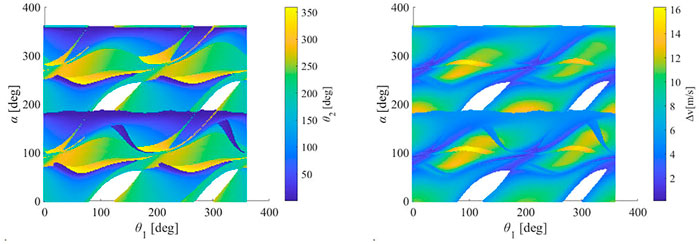
FIGURE 4. Distribution of phases and velocity differences at the reachable points (Δv1 = 5 m/s).
As shown in the left picture of Figure 4, the asymmetric characteristics of the free-flight trajectory departing the DRO can be seen. On the one hand, for any target phase of the DRO, a (θ1, α) combination can be found whose corresponding free trajectory returns this target phase. This indicates the global returnability of the target phase of the DRO. On the other hand, there are four blank areas which mean that not all the free trajectories from the departing phase θ1 can return DRO which highlights the non-global returnability of the DRO departure phase. In addition, these blank points do not completely represent unreturnable. When the time of flight is extended to a certain value, some free trajectories corresponding to the blank area return to the DRO. This implies that the blank area will narrow. As shown in the right picture of Figure 4, when the initial phase was near 100° or 300° (i.e., near the apolune), and the direction of departure pulse was near 100° or 300°, the velocity difference of the reachable point reaches its peak. This is probably because the velocity of the DRO near the apolune is relatively small, and the same pulse causes a greater change in the orbital state. Therefore, the speed difference was relatively large when the trajectory returned to DRO.
Intuitively, overall return probability γ is the proportion of the non-blank area in the distribution graph. When the magnitudes of the departure velocities were 2.5 m/s, 5 m/s, 10 m/s, 15 m/s, and 20 m/s, the overall return probabilities were 0.9288, 0.9246, 0.9206, 0.9142, and 0.9044, respectively. A larger value means that, under the simulation conditions, the probability of a spacecraft departing from the DRO and then returning to the DRO is high.
The returnable characteristics of free-flight trajectories departing from different phases of the DRO are shown on the top of Figure 5. Unaffected by the direction of the departure velocity, the departure phases in which almost 100% can return DRO are mainly distributed in two regions: [0°, 80°] and [230°, 260°], and the velocity difference of the corresponding return point was relatively small. When the phase in these regions is selected as the phasing start point (initial pulse application point), the phasing orbit has high fault tolerance for the pulse direction, high safety, and a small escape risk.
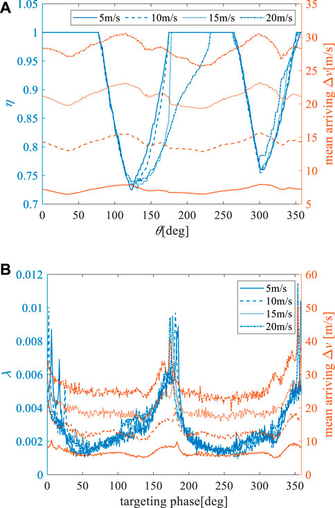
FIGURE 5. (A) Return probability of departure phase and mean arrival pulse, (B) the return probability of target phase and mean arrival pulse.
The return probability of the target phase and mean arriving pulse (velocity differences of the reentry points) are shown on the bottom of Figure 5. It was found that the phases with the highest return frequency were near the perilune of the DRO, and the corresponding velocity difference was larger. This indicates that under free-flight conditions, the collision risk near the perilune is higher. In addition, the larger the departure pulse, the larger the velocity difference in the arriving point. Significantly, departure phases and directions of departure velocity are uniformly sampled, while the corresponding free flight trajectories return to all phases of DRO unevenly. This is why λ fluctuates rapidly and also illustrates the complexity of orbits in cislunar space.
In this study, the effects of the initial phase, phase difference, and time of flight on the total pulse required for phasing were mainly considered in the analysis of the phasing capability of the DRO. A simple two-impulse phasing method is adopted. The two-impulse phasing model is shown in Section 3 and solved via a standard Newton iteration routine.
To analyze the effect of time of flight, the parameter Δt of the two-impulse phasing problem proposed in Section 3 is also taken as an unknown. In other words, the initial phase θt of target, initial phase θc of chaser, and initial phase difference Δθ are given, then the foresaid two-impulse phasing problem is solved. The phase angle of the rendezvous point is determined using Eq. 6. The parameters to be solved are Δv1, Δv2, and Δt.
The initial values of the departure velocity and flight time were given randomly. The value ranges of both were 0–100 m/s, and 0.2–2.5TDRO respectively. The target’s initial phase angles considered were 0°, 90°, 180°, 270° respectively. Initial phase differences are −90°, 90°, 180°. Therefore, there are 12 cases in total. For each case, the initial values were randomly assigned 500 times, and the two-impulse phasing problem was solved. Convergent solutions were recorded (solutions with excessive pulses were excluded). The minimum pulse solutions for each case are listed in Table 3. The corresponding flight times were greater than one TDRO.
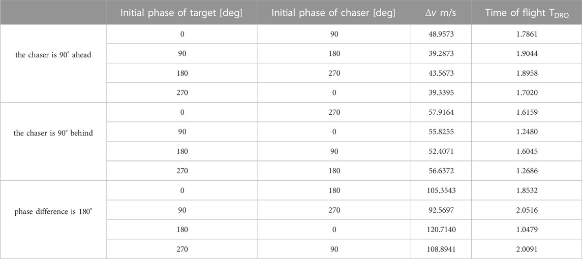
TABLE 3. Minimum pulse solutions.
For instance, the simulation results were analyzed when the initial phase of the chaser was 90° behind. The results are shown in Figure 6. In this figure, 0°–270° indicates that the initial phase angles of the target and chaser were 0° and 270°, respectively. Overall, the convergent solutions are concentrated on a curve descending along the x-axis. It indicates that the required Δv decreases with the increasing time of flight of phasing. When the flight time is more than one orbital period (right part of the convergent solutions figure), the convergent solutions are distributed on many curves, indicating that there are multiple solutions. Because of the existence of multiple solutions, if the initial value is not appropriate, the magnitude of the maneuver of the solution to the phasing problem is too large. This implies that the two-impulse phasing problem is sensitive to the initial value. The phasing orbits corresponding to the minimum pulse solutions inside the reference DRO are shown on the right side of Figure 6. On the left side of Figure 6, the curve where the minimum pulse solution is located is denoted as curve a. The phasing orbits corresponding to the points on curve a were also located inside the reference DRO. The phasing orbits corresponding to the points on the other curve were located outside and away from the reference DRO. Overall, increasing flight time can reduce the required pulse phasing. Thus, when the phasing maneuver is too large to violate the impulse constraint, a multiple-revolution phasing strategy can be adopted.
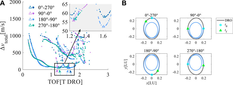
FIGURE 6. Results when the chaser is 90° behind. (A) Δv vs. TOF (the dots represent the convergent solutions. The triangles represent the solutions with Δvmin), (B) the phasing trajectory of minimum pulse solution.
The initial phase θt of target, initial phase θc of chaser, initial phase difference Δθ, and time of flight Δt are given, then the two-impulse phasing problem of Section 3 is solved. The phase angle of the rendezvous point is determined using Eq. 6. The parameters to be solved are Δv1, Δv2.
The simulation parameters are as follows: The time of flight of the phasing was fixed at one orbit period. The range of the initial phase difference is [−90°, 90°]. The range of the initial phase of target θt is [0°, 360°]. Because the time of flight is short, the case where the absolute phase difference is greater than 90 °is temporarily not considered.
The simulation results are presented in Figure 7. When the phase of the target was near 0°, 180°, and 360° (the ridge in the figure) at the initial time of phasing process, that is near the perilune, the required phasing pulse was relatively large. When the phase was near 90° and 270° (the saddle of the mountain in the figure), that is, near the apolune, the phasing pulse was small. The reason behind this may be that the velocity at the apolune of the DRO is small, so the velocity difference between the spacecraft is also small when the spacecraft moves to the apolune. From the perspective of reducing fuel consumption, the apolune is a more suitable target for phasing. Therefore, when there is a need for phasing, if the time requirement is relatively loose, the phasing operation can be performed after the spacecrafts move to the apolune.
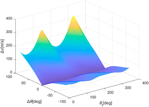
FIGURE 7. Δv vs. phase difference and initial phase (Δt = 1TDRO).
Among the simulation results, the initial phase differences conforming to the condition that the total phasing pulse was less than 50 m/s were found. The maximum and minimum initial phase differences are 45° and −64° respectively, which means that the range of adjustable phase difference is [−64°, 45°]. When the initial phase difference is outside this range, the phasing mission cannot be completed using a single two-impulse phasing under a pulse constraint. The maximum adjustable phase differences under different pulse constraints were obtained using the same method. The results are shown on the left side of Figure 8. It is found that the adjustable initial phase difference increases linearly with the increase of the maximum pulse constraint.
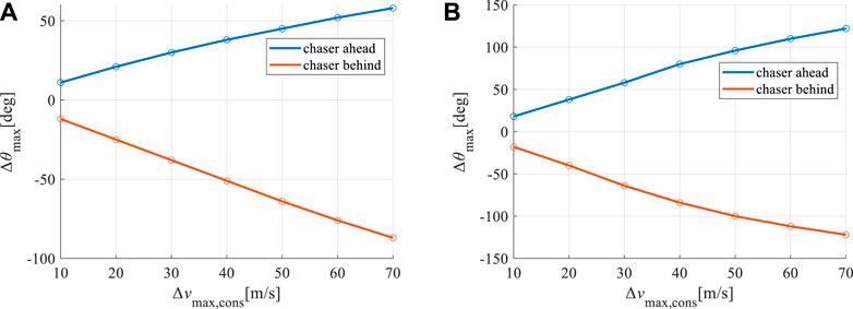
FIGURE 8. The phasing capability under the maximum pulse constraint. (A) Δt = 1TDRO, (B) Δt = 1.5TDRO.
The time of flight was added to the 1.5 TDRO. The range of the initial phase difference was [−180°, 180°]. The other simulation parameters remained constant. The maximum adjustable phase differences under different pulse constraints were obtained using the same method. The results are shown on the right side of Figure 8. The adjustable initial phase difference also increased linearly with an increase in the maximum pulse constraint.
When a phasing mission is provided, the initial phasing difference is generally known, whereas the initial/final phases and flight time of the phasing orbit are optional. The discussion in the previous section guides the selection of the initial phasing parameters. The returning capability analysis results provide a better value range for the starting point phase of the phasing orbit. Based on the results of the target phase returning characteristics and phasing capability analyses, for the purpose of safety and fuel economy, the final point of the phasing orbit should be selected near the apolune.
Next, a phasing optimization problem is presented and solved. The input parameter of this phasing problem is the phase difference Δθ, which is positive when the chaser is ahead. The optimization parameters are the initial phase of phasing orbit θc, final phase θr, the magnitude Δv1 and direction β of impulsive maneuver. The β is the angle between impulsive maneuver and x-axis. The range of β is [−180°, 180°]. The optimization objective was to minimize the total fuel cost. The final position error should be as small as possible to satisfy the endpoint position constraint. The time of flight was determined using Eq. 4. The optimization problem can be stated as follows:
where Δvtot is the total fuel cost. xtf,err represents the position error, k is the weighting coefficient, which is related to the balance between minimizing Δvtot and minimizing xtf,err. In this study, k is taken to be 2. According to the phasing capability analysis, increasing flight time can reduce fuel costs. Because the initial/final phase range is limited, time of flight can only be added by multiples of TDRO. Note that, to improve the convergence property, k is 10 under these circumstances.
The optimization problem is solved by genetic algorithm; though other global optimization algorithms such as particle swarm optimization or differential evolution algorithm may be also applicable (Zhu et al., 2020). As shown in Formula 9, the position error constraint is converted into a part of the objective function to achieve faster convergence. Taking phase differences of 5°, 10°, 20°, and 30° as examples, numerical examples are provided. The original optimization results and the results that Δt is added with one orbital period are shown in Table 4. This indicates that when time of flight increases, the total fuel cost decreases significantly.
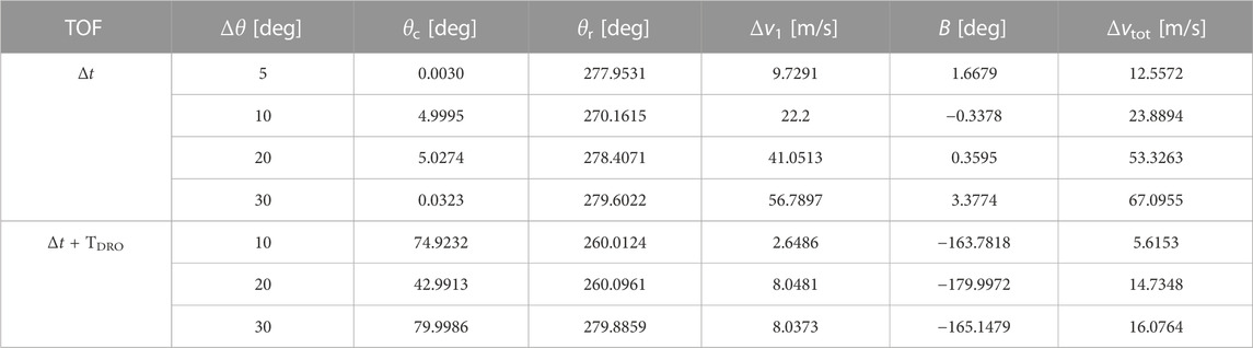
TABLE 4. Results of the phasing optimization problem.
In actual flight missions, the spacecraft’s trajectory is affected by various uncertain factors, such as orbit determination errors. The orbital period of a DRO is long and the terminal orbital errors will be larger because of the long duration of all types of error propagation. As shown in Figure 9, the accumulation of the orbit determination error over time leads to the endpoint of the two-impulse phasing orbit deviating from the reference trajectory. Terminal orbit errors of the phasing trajectory lead to an excessive relative distance between spacecraft, which may not meet the initial state requirements for rendezvous and docking missions.
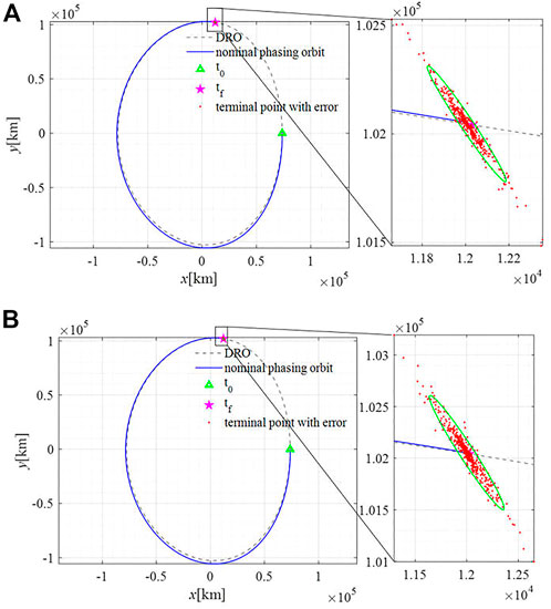
FIGURE 9. Terminal position distribution of two-impulse phasing orbit. (A) small orbit determination error, (B) large orbit determination error.
Consider the two-impulse phasing orbit as a reference, given the initial values of the splicing points. Thus, the actual phasing trajectory obtained using the multi-impulse phasing method is close to the two-impulse phasing trajectory. This guarantees that the phasing trajectory remains near the DRO. To reduce the influence of uncertain factors on the terminal orbit precision of the phasing trajectory, the rolling optimization strategy of model predictive control was used in this study, and a multi-impulse phasing rolling solution method was proposed. This method was verified using both CR3BP and ephemeris models.
As stated above, orbit phasing on DRO has a fairly long flight time. The terminal error is susceptible to various types of errors. Thus, several middle correction maneuvers can be applied in course when new orbit state is available. In the multi-impulse phasing process, the spacecraft flies freely for a period after the implementation of the first phasing maneuver. The phasing impulses are then solved again according to the new orbit determination state. A new maneuver was then implemented. These steps are repeated until the phasing operation is complete. This method is called the multi-impulse phasing rolling solution method because it updates the orbit state of the spacecraft several times and continuously calculates the phasing maneuver.
A process diagram of this method is shown in Figure 10. The steps are as follows:
0) The state at the initial time is the initial state of the chaser;
1) The initial state is used as the input, the two-impulse phasing trajectory is taken as a reference, then solve the N-impulse phasing problem and obtain the pulse sequence: Δvk, k = 1, … ,N;
2) Implement the first maneuver;
3) Update the orbit determination state of chaser at t2, take this value as the new initial state of chaser. Update N = N-1;
4) Return to step 1;
5) Repeat the above steps until N = 1.
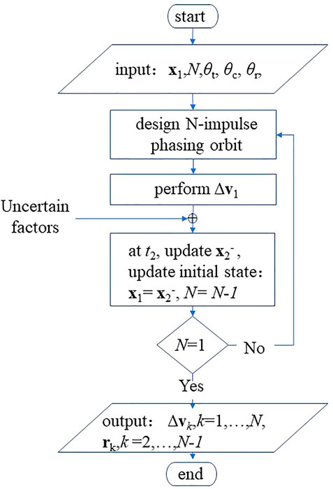
FIGURE 10. Diagram of multi-impulse phasing rolling solving method.
These multi-impulse phasing methods are feasible under both the CR3BP and ephemeris models.
In this section, the phasing trajectory evolution under an orbit determination error is analyzed using a Monte Carlo (MC) simulation. The number of simulations is set to 500. The uncertainty factors considered in this study are the two types of orbit determination errors that are listed in Table 5 (Liu et al., 2021). Every time the first maneuver was implemented, an orbit determination error was added to the initial state of the chaser. The phasing orbit without considering the orbit-determination error is called the nominal phasing orbit, and the pulse is called the nominal pulse.
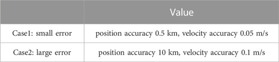
TABLE 5. Two types of orbit determination errors.
The case with a phase difference of 5° in Table 4 was used as an example to verify the multi-impulse phasing method. That is, θc is 0.0030°, θr is 277.9531°. The considered phase difference is only 5°; thus, it belongs to the tiny phasing category.
To provide a quantitative analysis of the orbit state errors, the end-position deviation of the phasing orbit is defined as follows: The error ellipse of the terminal position deviation distribution of MC simulation is projected onto the coordinate axis, then the half of the projection on the x and y directions are the position deviation, denoted as δx, δy. Thus, the total error of the phasing orbit is.
We considered five-impulse phasing as a numerical example. The two-impulse phasing optimal solution in Section 4.3 is used as the initial value, and the corresponding phasing orbit is used as the initial reference orbit. A nominal five-impulse phasing orbit was obtained, as shown in Figure 11. The phasing orbit remains near the DRO. Next, when the orbit determination error was considered, the required impulse and terminal position distribution of the phasing orbit with different numbers of impulsive maneuvers were analyzed.

FIGURE 11. Five-impulse nominal phasing orbit.
The pulses of the multi-impulse phasing are listed in Table 6. Compared to 12.5572 m/s two-impulse phasing, the total pulse of the multi-impulse phasing increased slightly. In addition, the total pulse required by the rolling-solving method was close to the nominal pulse of multi-impulse phasing. A smaller number of pulses is required in Case 1 than in Case 2. In the case of a small orbit determination error (Case 1), the terminal position errors δ of 2/3/4/5 impulse phasing orbit are 323 km, 69 km, 31 km, and 21 km. In the case of a large orbit determination error (Case 2), the 2/3/4/5 impulse phasing orbit errors δ are 661 km, 149 km, 77 km, and 51 km. With an increase in the pulse number, the position deviations decreased, which satisfied the requirement of the final relative distance between the spacecraft.
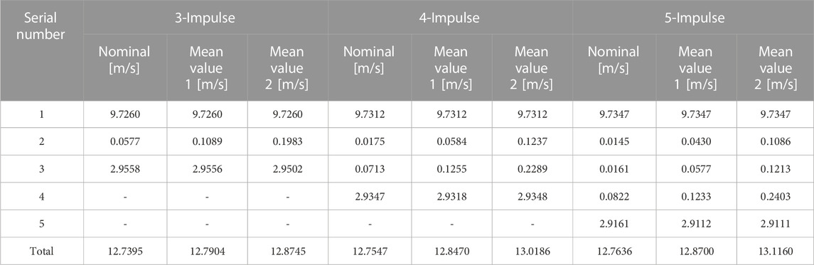
TABLE 6. Pulse statistical result of the multi-impulse phasing. (Value 1 means the results in case 1, value 2 means the results in case 2).
It is noteworthy to say that the ephemeris dynamical model is constructed in the inertial frame, while the DRO phase is defined in the rotation frame. In addition, the orbital state in the ephemeris model is related to the epoch. Therefore, special attention should be paid to the epoch and coordinate transformation when selecting the initial value to ensure that the phasing trajectory is close to the DRO reference orbit. Otherwise, the phasing trajectory is deviated from the reference orbit, increasing the phasing pulse.
The five-impulse nominal phasing trajectory under the ephemeris model without considering errors is shown in Figure 12.
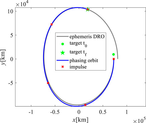
FIGURE 12. Five-impulse nominal phasing trajectory under ephemeris model.
The pulses of multi-impulse phasing under the ephemeris model are listed in Table 7. The impulse required for two-impulse phasing under the ephemeris model was 13.6400 m/s, compared to that of the CR3BP model which was 12.5572 m/s. With an increase in the number of phasing impulses, the total impulse also increased. Compared with the results of the CR3BP model, the total impulse of the multi-impulse phasing under ephemeris was slightly larger and may be related to the selection of the initial value. In the case of small orbit determination error (Case 1), the terminal position errors δ of 2/3/4/5 impulse phasing orbit are 350 km, 71 km, 30 km, and 23 km. In the case of large orbit determination error (Case 2), the terminal position errors δ of 2/3/4/5 impulse phasing orbit are 739 km, 178 km, 70 km, and 53 km. Similarly, as the number of phasing impulses increased, the terminal position deviation of the phasing trajectory decreased.
TABLE 7. The pulse statistical result of the multi-impulse phasing under ephemeris model. (Value 1 means the results in case 1, value 2 means the results in case 2).
A mathematical model of the phasing problem is presented in this study. The phasing characteristicsof the DRO were analyzed mainly from two aspects. First, from the perspective of returnability, the propagation characteristics of a free-flight orbit departing from the DRO were analyzed. Subsequently, the characteristics of the DRO phasing orbit were studied using the two-impulse phasing method. The effects of time of flight, initial/final phase, and phase difference on fuel cost were analyzed. A phasing optimization problem was proposed and solved based on the above analysis results. To mitigate the impacts of uncertain factors on the accuracy of the endpoint state of the phasing orbit, a multi-impulse phasing rolling solving method was proposed and verified using both the CR3BP and ephemeris models. This method considers errors and can also work effectively under the ephemeris model; thus, it has practical application significance.
The conclusions of the analysis of the DRO phasing capacity are as follows.1) The departure phases with the maximum DRO return probability are mainly distributed in [0°, 80°] and [230°, 260°]. 2) Extending the time of flight can reduce the phasing impulse; however, this reduction is limited. This is because the decreasing trend of the phasing pulse slows down with an increase in the TOF when the TOF is larger than 1.5 orbit period. 3) The impulsive maneuver capability limits the range of the adjustable phase difference, and the adjustable phase difference increases linearly with the increase of the maximum impulse constraint. The results of the multi-impulse phasing simulation are as follows: 1) In the case of a larger orbit determination error, the spacecraft is at risk of the terminal position deviation of the two-impulse phasing trajectory exceeding the initial relative distance requirement for the subsequent rendezvous operation. 2) The multi-impulse phasing rolling solution method can reduce the terminal position deviation of the phasing trajectory by reducing the error accumulation time and updating the orbital information several times. Compared to the two-impulse phasing method, the multi-impulse phasing method can reduce the position deviation from hundreds of kilometers to tens of kilometers, which meets the relative distance requirement for subsequent rendezvous operations. 3) In this study, two to five pulses are considered. With an increase in the number of pulses, the total fuel cost required for phasing increases slightly. Under the CR3BP model, the maximum total fuel cost required for multi-impulse phasing was approximately 13.1 m/s, whereas, under the ephemeris model, the total required fuel cost was approximately 14.3 m/s, both were within the acceptable pulse range. In addition, going from the CR3BP to the ephemeris model, the total pulse did not increase significantly.
The original contributions presented in the study are included in the article/supplementary material, further inquiries can be directed to the corresponding author.
HF completed the theoretical research, method design, simulation, and analysis, and writing and revision of the manuscript. HZ provided research guidance and wrote and reviewed the paper. MW provided the initial state of the ephemeris DRO.
This study was supported by the Strategic Priority Research Program of the Chinese Academy of Sciences (XDA30010200).
The authors declare that the research was conducted in the absence of any commercial or financial relationships that could be construed as a potential conflict of interest.
The handling editor YW declared a past co-authorship with one of the authors HZ.
All claims expressed in this article are solely those of the authors and do not necessarily represent those of their affiliated organizations, or those of the publisher, the editors and the reviewers. Any product that may be evaluated in this article, or claim that may be made by its manufacturer, is not guaranteed or endorsed by the publisher.
Bezrouk, C. J., and Parker, J. (2014). “Long duration stability of distant retrograde orbits,” in AIAA/AAS astrodynamics specialist conference (San Diego, CA.
Blazquez, E., Beauregard, L., Lizy-Destrez, S., Ankersen, F., and Capolupo, F. (2020). Rendezvous design in a cislunar near rectilinear Halo orbit. Aeronautical J. 124 (1276), 821–837. doi:10.1017/aer.2019.126
Blazquez, E., Beauregard, L., and Lizy-Destrez, S. (2018). “Safe natural far rendezvous approaches for cislunar near rectilinear halo orbits in the ephemeris model,” in 7th international conference on astrodynamics tools and techniques (ICATT) (Oberpfaffenhofen, Germany.
Bolliger, M. J. (2019). Cislunar mission design: Transfers linking near rectilinear halo orbits and the butterfly family. Purdue University Graduate School.
Bucchioni, G., and Innocenti, M. (2021). Phasing maneuver analysis from a low lunar orbit to a near rectilinear halo orbit. Aerospace 8 (3), 70. doi:10.3390/aerospace8030070
Camacho, E. F., and Alba, C. B. (2013). Model predictive control. Springer science & business media.
Canós, A. J. (2006). Fast and robust self-intersections [online]. MATLAB central file exchange. Available: https://www.mathworks.com/matlabcentral/fileexchange/13351-fast-and-robust-self-intersections [Accessed 2023].
Chen, H., and Ma, J. (2017). Phasing trajectories to deploy a constellation in a halo orbit. J. Guid. Control, Dyn. 40 (10), 2662–2667. doi:10.2514/1.G002518
Corpino, S., and Stesina, F. (2020). Inspection of the cis-lunar station using multi-purpose autonomous Cubesats. Acta Astronaut. 175, 591–605. doi:10.1016/j.actaastro.2020.05.053
Davis, D. C., Khoury, F. S., Howell, K. C., and Sweeney, D. J. (2020). “Phase control and eclipse avoidance in near rectilinear halo orbits,” in AAS guidance, navigation and control conference (Breckenridge.
Fossà, A., Bucchioni, G., Blazquez, E., Canalias, E., Lizy-Destrez, S., Bertrand, R., et al. (2022). Two and three impulses phasing strategy with a spacecraft orbiting on an Earth–Moon NRHO. Acta Astronaut. 198, 669–679. doi:10.1016/j.actaastro.2022.06.042
Franzini, G., and Innocenti, M. (2019). Relative motion dynamics in the restricted three-body problem. J. Spacecr. Rockets 56 (5), 1322–1337. doi:10.2514/1.A34390
Fuller, S., Lehnhardt, E., Zaid, C., and Halloran, K. (2021). “Gateway program status and overview,” in 72nd international astronautical congress.
Gao, Y. X., Ge, Y. M., Ma, L. X., Hu, Y. Q., and Chen, Y. X. (2019). Optimization design of configuration and layout for Queqiao relay satellite. Adv. Astronautics Sci. Technol. 2 (1-2), 33–38. doi:10.1007/s42423-019-00034-0
Gates, M., Muirhead, B., Naasz, B., McDonald, M., Mazanek, D., Stich, S., et al. (2015a). “NASA's Asteroid Redirect Mission concept development summary,” in 2015 IEEE aerospace conference. IEEE.
Gates, M., Stich, S., McDonald, M., Muirhead, B., Mazanek, D., Abell, P., et al. (2015b). The Asteroid Redirect Mission and sustainable human exploration. Acta Astronaut. 111, 29–36. doi:10.1016/j.actaastro.2015.01.025
Giordano, P., Grenier, A., Zoccarato, P., Swinden, R., Trenta, D., Schoenemann, E., et al. (2021). “Orbit determination and time synchronisation in lunar orbit with GNSS-Lunar Pathfinder experiment,” in IAC 2021 congress proceedings, 72nd international astronautical congress.
Holkar, K., and Waghmare, L. M. (2010). An overview of model predictive control. Int. J. control automation 3 (4), 47–63.
Liu, H. W., Li, W. J., Tian, B. Y., Ding, J. F., Zeng, F. M., Wang, Y. B., et al. (2019). Development and application of modular deep-space probe based on on-orbit assembly and maintenance. J. deep space Explor. 6 (6), 595–602. doi:10.15982/j.issn.2095-7777.2019.06.011
Liu, S., Yan, J., Cao, J., Ye, M., Li, X., Li, F., et al. (2021). Review of the precise orbit determination for Chinese lunar exploration projects. Wiley Online Library.
Lizy-Destrez, S., Beauregard, L., Blazquez, E., Campolo, A., Manglativi, S., and Quet, V. (2019). Rendezvous strategies in the vicinity of Earth-Moon Lagrangian points. Front. Astronomy Space Sci. 5, 45. doi:10.3389/fspas.2018.00045
Mayne, D. Q. (2014). Model predictive control: Recent developments and future promise. Automatica 50 (12), 2967–2986. doi:10.1016/j.automatica.2014.10.128
McCarthy, B. P., and Howell, K. C. (2021). Leveraging quasi-periodic orbits for trajectory design in cislunar space. Astrodynamics 5 (2), 139–165. doi:10.1007/s42064-020-0094-5
Murakami, N., Ueda, S., Ikenaga, T., Maeda, M., Yamamoto, T., and Ikeda, H. (2015). “Practical rendezvous scenario for transportation missions to cis-lunar station in Earth-Moon L2 halo orbit,” in Proceedings of the 25th international symposium on space flight dynamics (ISSFD) (Munich.
Murakami, N., and Yamanaka, K. (2015). “Trajectory design for rendezvous in lunar distant retrograde orbit,” in 2015 IEEE aerospace conference. IEEE.
Peng, C., Wen, C. X., and Gao, Y. (2018). DRO and HEO(3:1/2:1) resonant orbits in cislunar space calculated by continuation and their stability analysis. Manned Spacefl. 24 (6), 703–718. doi:10.16329/j.cnki.zrht.2018.06.001
Qi, Y., and de Ruiter, A. (2020). Achievable halo phasing with short-range trajectories. J. Guid. Control, Dyn. 43 (5), 928–938. doi:10.2514/1.G004751
Qin, S. J., and Badgwell, T. A. (2003). A survey of industrial model predictive control technology. Control Eng. Pract. 11 (7), 733–764. doi:10.1016/s0967-0661(02)00186-7
Sato, Y., Kitamura, K., and Shima, T. (2015). Spacecraft rendezvous utilizing invariant manifolds for a halo orbit. Trans. Jpn. Soc. Aeronautical Space Sci. 58 (5), 261–269. doi:10.2322/tjsass.58.261
Schulte, P. Z., Spehar, P. T., and Woffinden, D. C. (2020). “GN&C sequencing for Orion rendezvous, proximity operations, and docking,” in Annual AAS guidance, navigation and control conference.
Singh, S., Junkins, J., Anderson, B., and Taheri, E. (2021a). Eclipse-conscious transfer to lunar gateway using ephemeris-driven terminal coast arcs. J. Guid. Control, Dyn. 44 (11), 1972–1988. doi:10.2514/1.g005920
Singh, S. K., Anderson, B. D., Taheri, E., and Junkins, J. L. (2021b). Exploiting manifolds of L1 halo orbits for end-to-end Earth–Moon low-thrust trajectory design. Acta Astronaut. 183, 255–272. doi:10.1016/j.actaastro.2021.03.017
Singh, S. K., Anderson, B. D., Taheri, E., and Junkins, J. L. (2021c). Low-Thrust transfers to southern $$L_2$$ near-rectilinear halo orbits facilitated by invariant manifolds. J. Optim. Theory Appl. 191 (2-3), 517–544. doi:10.1007/s10957-021-01898-9
Smitherman, D. V., and Griffin, B. N. (2014). “Habitat concepts for deep space exploration,” in AIAA space 2014 conference and exposition.
Zhao, Y. S., Shi, P., and Zhang, C. (2016). Deep space flight dynamics. Beijing: China Astronautic Publishing House.
Keywords: phasing, distant retrograde orbit (DRO), circular restricted three-body problem, returning capability, multi-impulse maneuver
Citation: Fu H, Wang M and Zhang H (2023) Phasing analysis on DRO with impulsive maneuver. Front. Astron. Space Sci. 10:1177573. doi: 10.3389/fspas.2023.1177573
Received: 01 March 2023; Accepted: 17 April 2023;
Published: 04 May 2023.
Edited by:
Yue Wang, Beihang University, ChinaReviewed by:
Yi Qi, Beijing Institute of Technology, ChinaCopyright © 2023 Fu, Wang and Zhang. This is an open-access article distributed under the terms of the Creative Commons Attribution License (CC BY). The use, distribution or reproduction in other forums is permitted, provided the original author(s) and the copyright owner(s) are credited and that the original publication in this journal is cited, in accordance with accepted academic practice. No use, distribution or reproduction is permitted which does not comply with these terms.
*Correspondence: Hao Zhang, aGFvLnpoYW5nLnpockBnbWFpbC5jb20=
Disclaimer: All claims expressed in this article are solely those of the authors and do not necessarily represent those of their affiliated organizations, or those of the publisher, the editors and the reviewers. Any product that may be evaluated in this article or claim that may be made by its manufacturer is not guaranteed or endorsed by the publisher.
Research integrity at Frontiers
Learn more about the work of our research integrity team to safeguard the quality of each article we publish.