 Marc Gagnon
- Biorex Inc., Québec, QC, Canada
A global inventory of extractive species mariculture in wave-exposed temperate waters shows that the longline is the technology used in more than 99% of the sites (Part 1 of this review). In this second part, I compare the static (longline at rest), quasi-static (tidal sea surface elevation, steady currents and mainline lifting operation) and dynamic (wind seas and swells) loading and motion of surface, semi-submerged and fully submerged longlines used to grow bivalves and kelp. This review is based on a hundred papers published on the subject mostly after 2010 and on simple analytical models used to illustrate the many compromises that must be made to ensure the survivability of the structure and the survival (retention), growth and quality of the cultured biomass. Surface longlines are unsuitable for fully exposed environments. To mitigate storm energy it is necessary to minimize the volume of surface buoys and submerge the mainline to the maximum depth possible. There is however a limit to minimizing the volume of surface buoys due to the uplifting of the mainline by currents. In the case of kelp, its optimal growing depth is within a few meters from the sea surface. This limitation can be partly circumvented by having the kelp float above the mainline. In the case of bivalves, mainline depth can be tens of meters below the sea surface. This comes with some disadvantages including difficulties in maintaining the delicate buoyancy balance, particularly for fully submerged longlines without legs, and reduced access to the mainline, particularly for fully submerged longlines with legs. Devices that allow autonomous or remote-controlled changes of mainline depth on a daily, occasional (husbandry and harvest operations) or seasonal basis have been tested but are not yet used commercially on longlines.
1 Introduction
Aquaculture is currently expanding offshore in more exposed sites in response to the increasing demand for seafood and seaweed. As defined by Buck et al. (2024), exposed sites are unprotected from strong currents, large waves and strong winds and they may be near to land or far offshore. Compared to sheltered sites, exposed sites have several potential advantages, including more space (larger leases), fewer user conflicts, more stable and better water quality, better growth of the cultured biomass and fewer environmental impacts. However, they also have several disadvantages, including the need for larger and more powerful vessels, shortened operating window, increased risks of structural failure and cultured biomass loss caused by storms, and increased risks of marine mammal entanglement and for human health & safety (ICES, 2012; Lovatelli et al., 2013; Mizuta and Wikfors, 2019; Yang et al., 2020; Mascorda Cabre et al., 2021; Bath et al., 2023).
The companion article (Part 1) to this paper (Gagnon, 2024) presents a systematic inventory of extractive species (non-fed) off-bottom commercial farms in exposed temperate waters. This inventory shows that shellfish, tunicate and kelp grow-out in wave exposed sites (as defined in Part 1) are currently absent in many regions with a large extent of sheltered sites such as Norway, Scotland (UK), British-Columbia (Canada), Alaska (USA) and southern Chile. They are a new venture since 2010 in many countries such as Portugal, Spain, Turkey and New Zealand and have been practiced for more than 30 years in Japan and France. The longline (LL) is the culture method used in more than 99% of the exposed farms. In the sites for which the information is available, the submerged LL on which the cultured biomass is maintained more than 2 m below the sea surface is the adopted design.
Currently, the main constraint to extractive species aquaculture in exposed sites is its low profitability (van den Burg et al., 2017a, 2017b). Capital and operational costs are higher compared to those in sheltered sites while the market value of the cultured biomass remains relatively low compared to fin-fishes. Up-scaling, mechanization, and automation of farm installation, seeding, monitoring, and harvesting operations still need to be developed and tested. However, the survivability of the structures and the survival (retention), growth, and quality of the cultured biomass in exposed sites remain crucial. These depend largely on how much the lines and anchors are loaded and the cultured biomass is agitated by currents, waves and husbandry operations.
Few reviews focus on the loading and motion of longlines in currents and waves and most of them are technical reports that have limited diffusion and are more than 10 years old. Bompais (1991) provides an in-depth review of the design of various types of LLs and Priour (1995) reviews mooring and anchoring alternatives applicable to LLs. Gagnon and Bergeron (2011, 2014) review the various designs of submerged longlines, the physical and hydrodynamic characteristics of their components and buoyancy management alternatives applicable to this type of LL. Since these early reviews, more than 70 original research papers on various case studies have been published (Supplementary Table S1A and B). These include in-situ measurements of the tension in the lines and the motion of buoys and suspensions (e. g. mussel droppers, lantern nets, kelp-lines), tests on full-scale and physical models of suspensions and complete longlines in current and wave flumes as well as static and dynamic LL simulations using numerical modelling. It is out of the scope of the present paper to make a systematic review of this extensive literature. The purpose of this article is rather to compare the loading and motion of three types of longlines (surface, semi-submerged and fully submerged) used to grow bivalves and kelp on four types of well-documented suspensions (mussel droppers, scallop lantern nets, horizontal kelp-lines and floating vertical kelp-lines) and to review how farm layout affects currents and waves inside the farms. Section 2 provides a description of the LL components, LL types and suspension case studies. The static equilibrium attained by LLs in the absence of external forces is addressed in Section 3. Section 4 covers the quasi-static equilibrium attained by LLs when lifted to the sea surface and forced by tidal sea surface elevation and steady currents. Finally, Section 5 addresses how LL design affects their loading and motion by wind seas and swells.
2 Longline components, longline types and suspension case studies
A longline (LL) consists of a long horizontal rope (mainline or backbone) supported by buoys (floats) and anchored individually to the sea bed at both ends or in arrays of several parallel ropes anchored by a grid of mooring lines. The following descriptions of the LL components and LL types are based on reviews by Bompais (1991) and Goseberg et al. (2017) and the LL designs used on wave exposed commercial farms (Gagnon, 2024). Figure 1 provides a schematic illustration of the types of LLs and their main components.
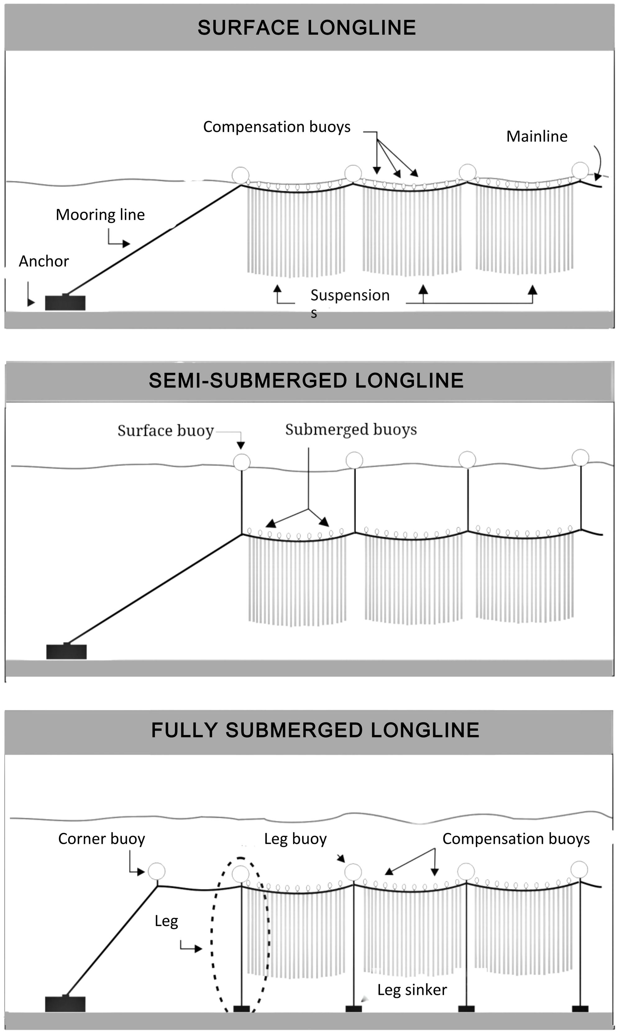
Figure 1. Schematic representation of the three types of longlines compared in this article. Not to scale.
2.1 Longline components
2.1.1 Anchors
The various types of anchors used to ensure station-keeping are deadweight anchors, screw anchors, drag embedment anchors and piles. Unless their holding capacity is exceeded, their characteristics have no effect on LL loading and motion and for this reason they are not further discussed in this review.
2.1.2 Lines
The main types of lines on a individually anchored LL are the mainline (ML), the mooring lines, the legs, the dropper lines, the kelp-lines and the lines used to attach the buoys and suspensions to the mainline. The mainline is the long horizontal rope to which the suspensions, the compensation buoys and, for some types of LLs, the legs are attached. The mooring lines are attached between both ends of the mainline and the anchors; their main function is to transmit the forces exerted on the ML to the anchors. The legs are vertical lines attached between the mainline and sinkers resting on the sea bottom; their main function is to keep the ML at a constant depth above the sea bottom. The dropper line and kelp-lines are described in Section 2.3. All these lines are usually synthetic fiber ropes which are nearly neutrally buoyant (Table 1). Their buoyant weight (weight in water) has a negligible effect on the buoyancy balance unless they are covered by a thick layer of biofouling (see Section 2.1.4). Their elasticity is important in determining the geometry of the longline. For given rope type and tension, rope elongation (% of initial length) is roughly inversely proportional to the squared rope diameter (Fredheim and Lien, 2001).
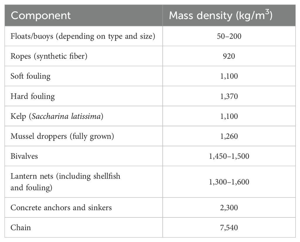
Table 1. Typical values of the mass density of longline components (WHOI, 1952; Yamamoto et al., 1988; Gagnon and Bergeron, 2011; Macleod et al., 2016).
2.1.3 Buoys (floats)
On individually anchored LLs, four types of buoys can be distinguished: corner buoys, compensation buoys, leg buoys and tensioner buoys. Corner buoys are large buoys (or a combination of many small ones) placed at the junction of the mainline and mooring lines; their main function is to exert a pretension in the lines. Compensation buoys are attached along the mainline to compensate the buoyant weight of the suspensions and fouling on the lines and buoys. Leg buoys are attached at the junction of the legs and ML; their function is to keep the legs taut thus maintaining constant the height above the bottom of fully submerged LLs. Tensioner buoys used on some LLs are submerged floats attached to the mooring lines at some distance from the anchors; their main function is to dampen the forces exerted on the mooring lines by sea surface elevation. Most submerged buoys are pressurized thick-walled hollow or foam-filled plastic buoys. Their mass density (kg/m3) depends on their shape, size and make (Table 1). The effective buoyancy of surface buoys depends on their degree of submergence while submerged floats that resist the local hydrostatic pressure have a constant effective buoyancy. Buoys must resist the hydrostatic pressure to which they are submitted during the grow-out cycle. Even buoys designed to remain at the sea surface must be able to withstand pressures > 1 bar because they will likely be pulled at greater depths in various situations including drag forces on the LL and the loss or implosion of adjacent buoys (Bompais, 1991; Fredheim and Lien, 2001).
2.1.4 Fouling
When left uncleaned for several months, lines, buoys and nets can be colonized by large volumes of biofouling. Soft fouling (seaweeds, anemones, tunicates, hydroids) is nearly neutrally buoyant while hard fouling (mussels, barnacles, tube worms) have a mass density similar to that of mussel droppers (Table 1). In temperate waters on the continental shelf mussels are by far the main contributor to the fouling buoyant weight on buoys and lines (WHOI, 1952; Macleod et al., 2016; Bannister et al., 2019). The lines and buoys on the part of the ML accessible from the sea surface are usually cleaned during husbandry operations but the inaccessible part of the ML, the mooring lines, tensioner and corner buoys and the legs are usually covered by a thick layer of mature mussels within several months (Paul and Grosenbaugh, 2000; Buck, 2007; Gagnon and Bergeron, 2014).
2.1.5 Sinkers
Sinkers are usually concrete blocks of various sizes that are attached to the bottom end of the legs, kelp-lines on surface and semi-submerged LLs to maintain their depth constant and to mooring lines with or without tensioner buoys to dampen the effects of sea surface elevation. The buoyant weight of concrete is roughly 55% of its weight in air (Table 1).
2.2 Longline types
In this article, the following three types of LLs are compared (Figure 1): surface, semi-submerged and fully submerged. The latter two may be fitted with legs or not (Table 2). To illustrate the effect of some parameters, a standard longline (StdLL) will be used in the following sections. The characteristics of this standard longline are given in Table 3.
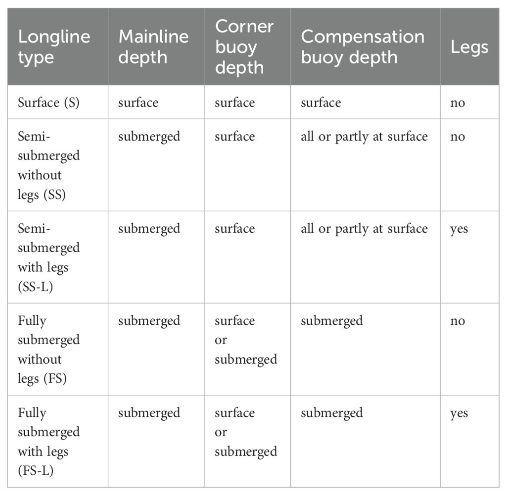
Table 2. Longline type definitions based on the designs currently used in wave exposed sites (Gagnon, 2024).
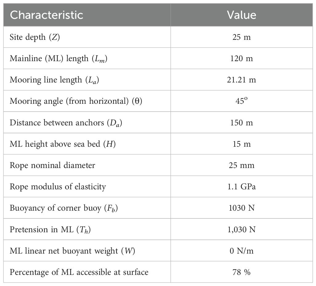
Table 3. Characteristics of the standard longline (StdLL).
2.3 Suspension case studies
The suspensions are the ropes, cages, nets and other structures with the cultured biomass and fouling they contain or hold that are attached along the ML. This article focuses on the following four types of suspensions: 1) blue mussel droppers, 2) scallop lantern nets, 3) horizontal kelp-lines, and 4) floating vertical kelp-lines. Table 4 presents the characteristics of these four case studies.
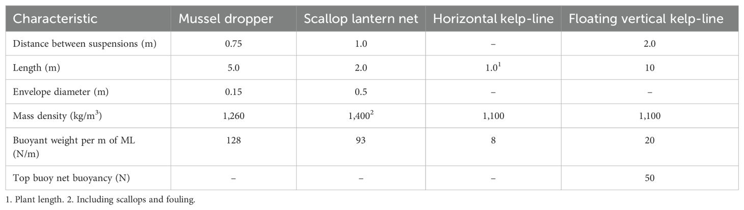
Table 4. Characteristics of the four suspension case studies.
2.3.1 Mussel dropper
The first case study is a typical fully grown blue mussel (Mytilus edulis) dropper that is seeded with juvenile mussels (15 to 25 cm length) and is grown until harvest (average length of 5.5 to 6 cm) in 10 to 24 months, depending on latitude. The physical and hydrodynamic characteristics of mussel droppers are reviewed by Gagnon and Bergeron (2011) and Gagnon (2019) and are summarized in Table 4. They consist of a central rope to which mussels attach by their byssal threads to form a dense cylindrical and porous matrix. Mussels can be grown at a relatively large depth where good conditions for growth may be found (Mizuta and Wikfors, 2019; Gagnon, 2024). The droppers can be vertical droppers of various lengths individually attached along the mainline. Their buoyant weight at seeding is high enough that there is no need to attach a sinker at their bottom end. Another technique consists of attaching very long droppers (continuous droppers) in consecutive loops along the mainline. When the biomass is evenly distributed along the dropper and no sinker is attached at the dropper free end, this type of suspension may be modeled as a free hanging rigid circular cylinder (bluff body).
2.3.2 Scallop lantern net
The second case study (Figure 2) is the lantern net used for the final grow-out phase of the Japanese scallop (Mizuhopecten yessoensis). The cylindrical enclosure consist of circular metal frames covered by a net of various mesh sizes (depending on scallop size) and is subdivided into 10 superposed chambers by porous floors. Juveniles are grown to market size in these enclosures during 18 to 30 months (Kosaka, 2016). Scallops are very sensitive to wave induced motion and are usually grown at depths of more than 10 m. Lantern nets are individually attached to the mainline at intervals of roughly 1 m. Their buoyant weight at seeding is high enough that there is no need to attach a sinker at their bottom end. Their physical and hydrodynamic characteristics depend on the level of fouling and the weight of the scallop biomass. Table 4 provides the characteristics of a typical fouled lantern net containing fully grown scallops (Yamamoto et al., 1988; Wang et al., 2023). When the biomass is evenly distributed in the enclosure, this type of suspension may also be modeled as a free hanging rigid circular cylinder (bluff body).
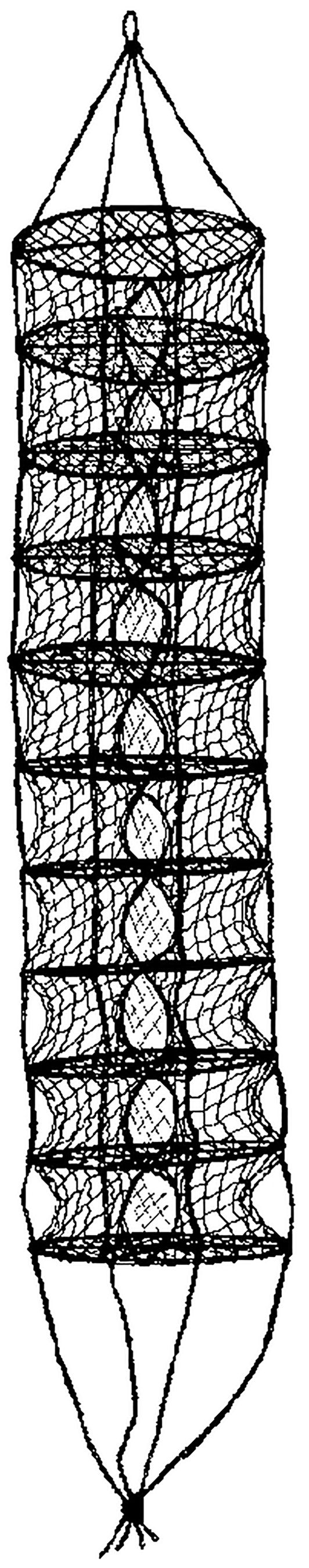
Figure 2. Example of an empty lantern net.
2.3.3 Kelp-lines
Cases 3 and 4 are sugar kelp (Saccharina latissima) fully grown kelp-lines attached to the longline with two different methods that have a significant effect on their hydrodynamic characteristics: the horizontal kelp-line and the floating vertical kelp-line. S. latissima is composed of a single long blade, a short stipe and a holdfast. In commercial farms, these suspensions are currently seeded by winding around the kelp-line a string that holds a high density of small plants (length< 1 cm). Hundreds of plants per m attach by their holdfast around the circumference of the kelp-line while the blades are free to move with the currents and waves. The kelp-line may be the ML itself or a rope placed parallel and under the ML (horizontal kelp-lines) or several vertical ropes attached along the ML with a buoy attached at their free end (floating vertical kelp-line; Bak et al., 2018). Table 4 provides the characteristics of typical kelp-lines at harvest. They differ from mussel droppers and scallop lantern nets in many ways. Firstly, kelp needs sufficient light to grow so it must be kept near the surface in the case of the horizontal kelp-line and at a maximum of 10 m in relatively clear water in the case of the floating vertical kelp-line. Secondly, grow-out time is much shorter (6–9 months including the winter season) than for the mussel dropper and scallop lantern net and does not include the summer fouling season; consequently, the buoyant weight of fouling on kelp-lines at harvest is negligible. Thirdly, the mass density of kelp is nearly neutral. The buoyant weight of the kelp-lines per m of mainline is nearly zero at the start and is one order of magnitude lower than that of the mussel and scallop longlines at harvest (Table 4). In the case of the horizontal kelp-line, sinkers are usually attached to the mainline to maintain it at the design depth (Flavin et al., 2013). Fourthly, kelp-lines can be partially harvested by cutting the blades above their junction with the stipes and the blades regrow from the stump left on the line (Bak et al., 2018). Finally, kelp-lines cannot be modeled as bluff bodies because their shape changes significantly with changing current velocity and angle of attack (see Section 4.3.1).
3 Static analysis
In the absence of currents, waves and other external forces (LL at rest), the LL reaches a static equilibrium that depends on its geometry and the balance between the buoyancy and the buoyant weight of its components. Of particular interest in static conditions are the pretension and the sag in the ML and buoyancy management alternatives.
3.1 Pretension in mainline
When the LL is at rest, the tension in the ML is called the “pretension”. This force depends mostly on the mooring geometry and the effective buoyancy of the corner buoys which may be at the sea surface or submerged. In the case of LLs with submerged corner buoys of effective buoyancy (), if we assume to simplify that the mainline is neutrally buoyant and the mooring line is a simple rope of length which makes an angle θ with the horizontal (Figure 3), from basic geometric force analysis (Gagnon and Bergeron, 2014), the horizontal tension in the ML is given by Equation 1:
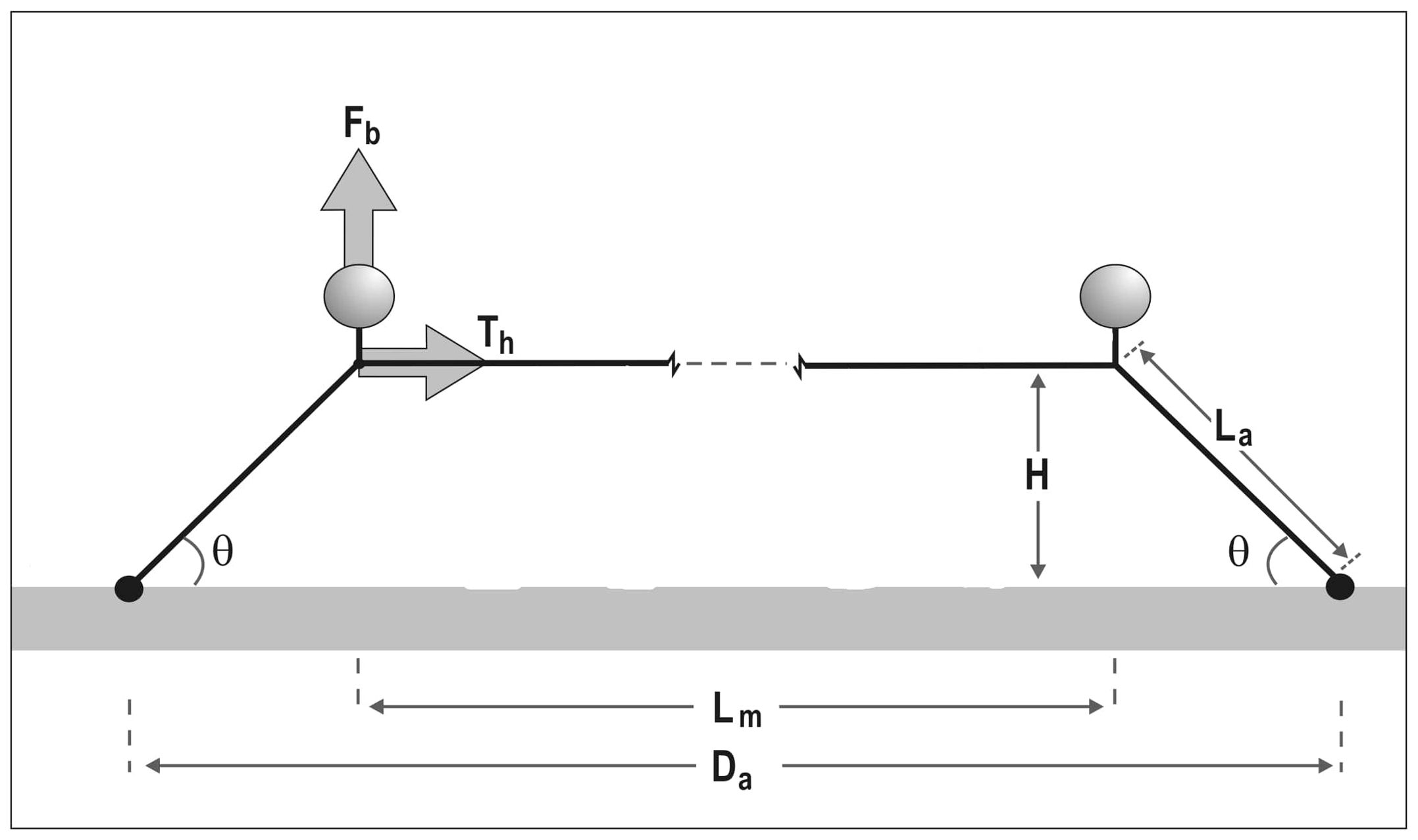
Figure 3. Diagram explaining how the pretention in the mainline (Th) is determined by the LL geometry and the effective buoyancy of the corner buoys (Fb). Da: distance between the anchors; Lm: ML length; La: mooring line length; H: ML height above the sea bottom; θ: mooring angle.
The horizontal component of the pretension in the ML () increases with increasing buoyancy of the submerged corner buoys and with the increasing length of the mooring line (decreasing θ); it is zero when θ = 90° (), equal to when θ = 45° and infinite when θ = 0°. If we assume that the lines are stiff (no elongation), the distance between the anchors () and the height of the ML above the sea bottom (H) are given by Equation 2:
where is the length of the ML. From the above it can be seen that if the distance between the anchors is increased without changing and , θ decreases, the pretension () increases and the ML height above the bottom (H) decreases. Conversely, if decreases the pretension decreases and the ML height increases.
In the case of surface corner buoys, the pretension in the ML is maximal when these buoys are fully submerged. If is decreased from that situation, the corner buoys progressively emerge, their effective buoyancy decreases and the pretension in the ML decreases. At a certain value of the corner buoys are fully emerged and the ML becomes slack. The range where the corner buoys go from fully emerged to fully submerged is smaller for spherical buoys than for pencil (spar) buoys as illustrated in Figure 4. Thus, LLs with surface corner buoys require higher precision in anchor placement and are more sensitive to anchor movement (slippage) than LLs with submerged corner buoys. Spar corner buoys are preferable to spherical ones when they are positioned at the sea surface (Bompais, 1991).
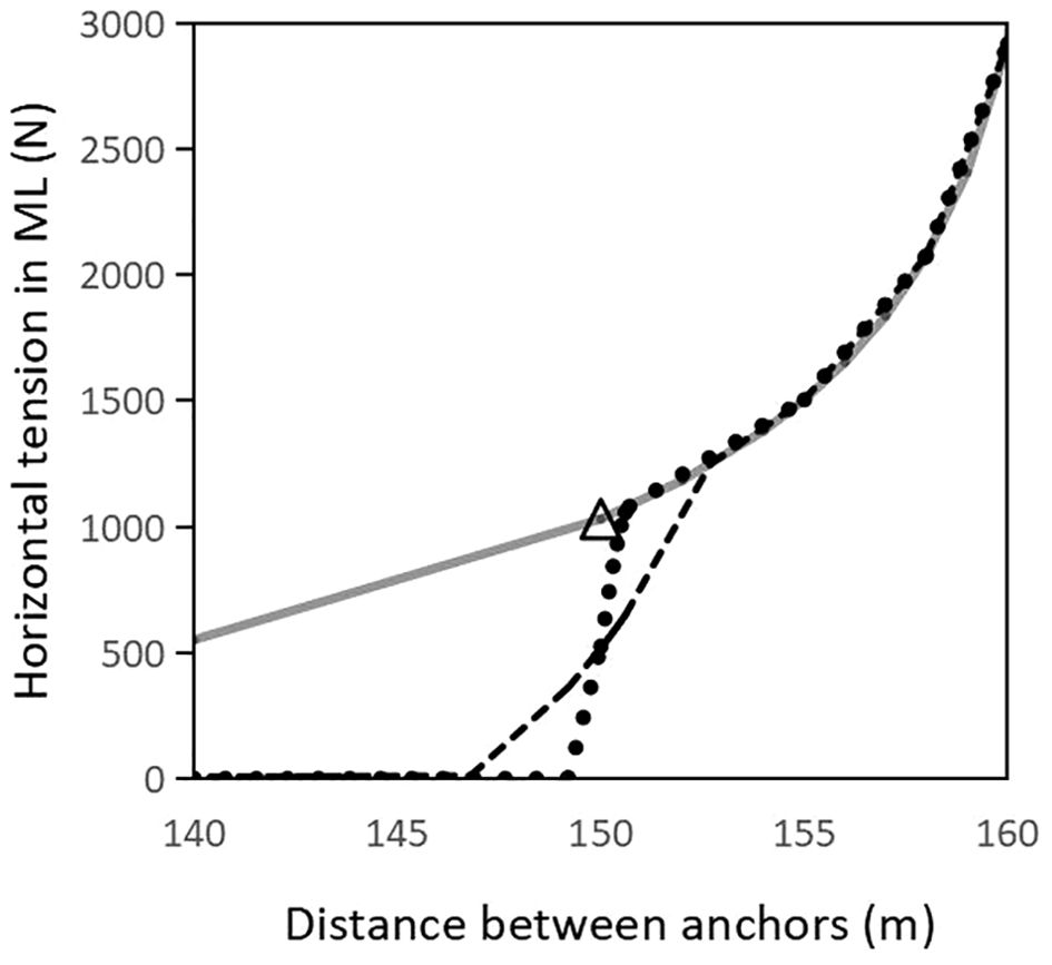
Figure 4. Variation of the horizontal component of pretension in the mainline as a function of the distance between anchors with submerged corner buoys (full gray line), spar surface corner buoys (dashed line) and spherical surface corner buoys (dotted line). The triangle is the standard LL (Table 3).
3.2 Sag in mainline
When the LL is at rest the ML is supported by the buoys with a buoyancy reserve and the ML segments between these supports sags towards the bottom if their net mass density (suspensions, fouling and submerged floats included) is higher than that of sea water or rises towards the surface in the opposite situation. The position of the support floats depends on the type of LL. On surface and semi-submerged LLs, all surface floats act as supports. On fully submerged LLs without legs only the corner buoys act as supports. Finally, on fully submerged LLs with legs, the corner buoys and the leg floats with a buoyancy reserve act as supports. The sag between two supports can be estimated by using the parabolic approximation (Equation 3) (Gagnon and Bergeron, 2014):
where the Sag is vertical distance (m) from the supports attained by the middle point of the ML segment (positive when the mainline sags downward), the span (S) is the horizontal distance (m) between the supports; W is the linear net buoyant weight or the net buoyancy (N/m) of the ML segment between the supports; and is the length (m) of the ML segment. Since the sag is proportional to the squared span (S2), fully submerged LLs without legs are prone to large sags if the buoyancy is not adjusted frequently to minimize W. This type of LL is fitted with large corner buoys (large ) for that reason (Langan and Horton, 2003). With all other variables constant, adding one leg in the center of a fully submerged LL (i.e. reducing the span roughly by half) reduces the sag in each of the two spans by 75% and adding three equally spaced legs (reducing the span by 75%), reduces the sag in each of the four spans along the ML by 94%.
3.3 Buoyancy management
During a normal grow-out cycle, the weight of the cultured biomass and biofouling increases continually. In temperate waters, kelp and bivalve growth is relatively slow during the winter and fast during spring and summer while the fouling on a newly installed LLs usually starts to affect the buoyancy balance only during the first summer. This increasing weight must be compensated by adjusting the buoyancy installed on the ML and, between buoyancy adjustments, by the buoyancy reserve on the ML. A buoyancy reserve can only be installed on surface buoys or leg buoys. Moreover, lifting a submerged ML to the sea surface to adjust its buoyancy is time consuming, often requires a trial and error process and may have harmful effects on the cultured biomass (fall-off, shell breaking, reduced growth; Matsubara, 2000; Myamoto et al., 2020). In the case of surface and semi-submerged LLs, the frequency of buoyancy adjustments must be relatively frequent because the presence of a large buoyancy reserve in the surface buoys increases the risks of unwanted wave effects (Bompais, 1991; Langan et al., 2010). In the case of fully-submerged LLs without legs, buoyancy management is a critical element of their operation. The only way to keep the mainline close to the design depth is to add buoyancy frequently during the grow-out cycle. When unsuitable weather conditions or other problems prevent buoyancy adjustments a large sag may appear in the ML, buoys may implode due to their increased depth and a chain reaction may occur resulting in the complete collapse of the ML to the sea bottom (Fredheim and Lien, 2001; Langan et al., 2010; Lindell, 2015). Finally in the case of fully-submerged LLs with legs, three alternatives are possible (Figure 5): 1: frequent buoyancy adjustments, 2: a few buoyancy adjustments; or 3: no buoyancy adjustments by installing on the legs at the start a buoyancy reserve that will be sufficient to compensate the projected weight at harvest (the “set and forget” approach; Goseberg et al., 2017). One problem with the third alternative is that the net weight that must be lifted to the sea surface for servicing and harvesting (including the weight of the leg sinkers) increases constantly until harvest time as illustrated in Figure 5I. However, if a single buoyancy adjustment is made during the grow-out cycle (Alternative 2), the weight of the leg sinkers can be reduced considerably as is the force required to lift the ML to the sea surface at harvest (Figure 5F).
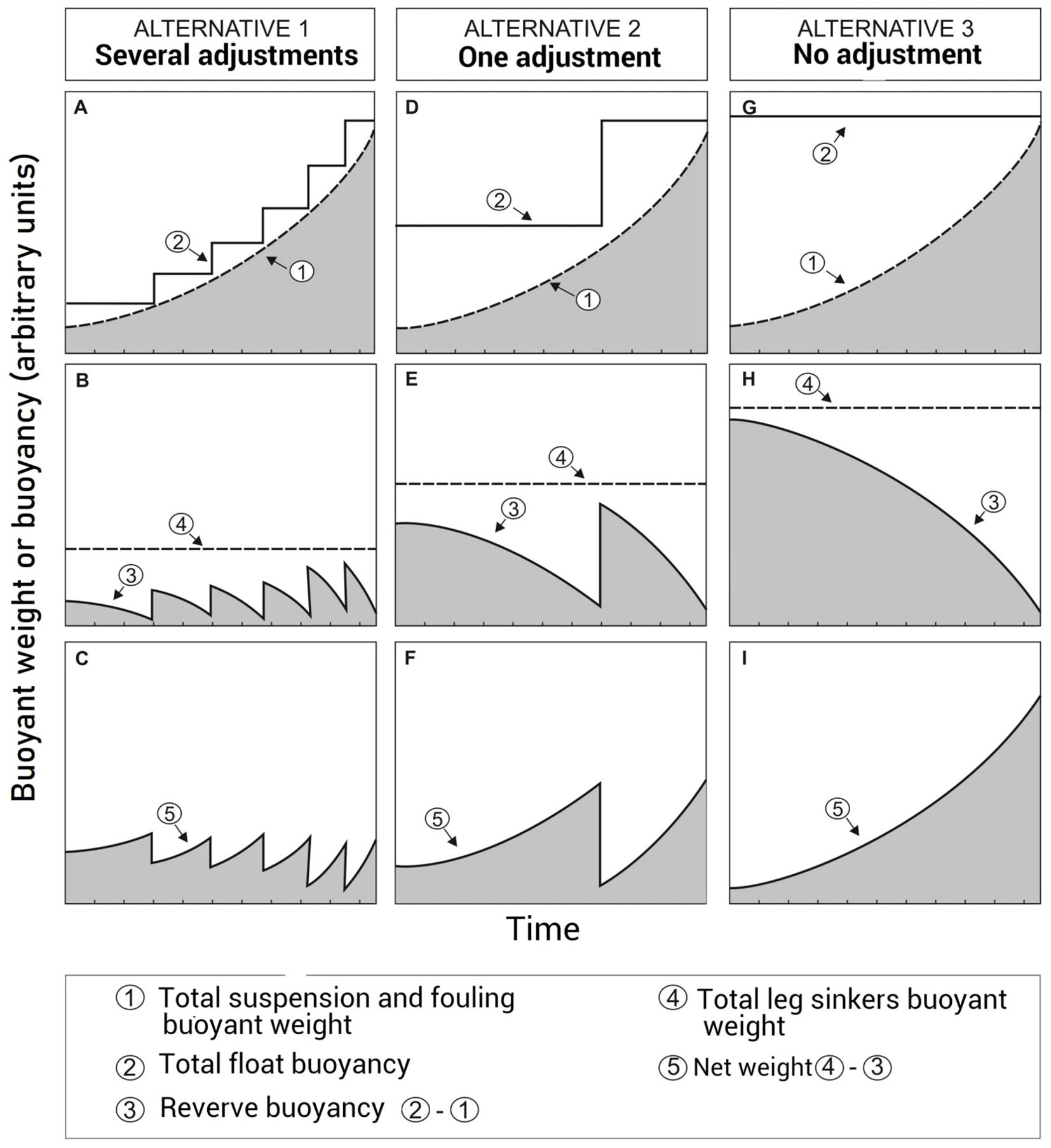
Figure 5. Buoyancy management alternatives for a fully submerged longline with legs. (A–C) Several buoyancy adjustments during the grow-out cycle; (D–F) one adjustment; (G–I) no adjustment required. (A, D, G) evolution of the total buoyant weight of the suspensions and fouling and total buoyancy of the compensation buoys; (B, E, H) evolution of the buoyancy reserve and total buoyant weight of the leg sinkers; (C, F, I) evolution of the longline net buoyant weight (buoyant weight of leg sinkers minus buoyancy reserve).
4 Quasi-static analysis
When external forces acting on a LL are slow-varying the LL attains a quasi-static equilibrium. Such forces are exerted by steady currents, tidal sea surface elevation and when the ML is lifted to the sea surface in the absence of waves.
4.1 Mainline lifted to the sea surface
The force that can be used to lift the ML to the sea surface is limited by the lifting capacity of the vessel, the breaking strength of the lines and holding capacity of the anchors. One disadvantage of semi-submerged and fully submerged LLs is that a part of the ML at both ends is usually not accessible from the surface (Bonardelli, 1996). Bergeron and Gagnon (2003) developed a simplified model to approximate the percentage of the mainline accessible from the surface based on the basic geometry of an ellipse where the focal points are the anchors and the sum of the distances of a point on that ellipse to the two focal points is equal to the total length of the ropes (Figure 6). This model provides a rough estimate of the percentage accessible as a function of Lm, La (or θ), ML height above the bottom (H), water depth (Z) and rope elongation (as a surrogate for the maximum allowable tension in the lines when one end of the ML is lifted 3 m above the sea surface). Figure 7 presents how these variables affect the percentage accessible for the StdLL (Table 3). With all other variables constant, this percentage increases with increasing ML length (Figure 7A), decreasing ML depth (Figure 7B), decreasing site depth, increasing rope elongation (Figure 7C), and decreasing rope diameter. The effect of mainline length is significant only for lengths smaller than 200 m. The effect of the mooring angle (which decreases with increasing mooring line length) is complex (Figure 7D): with stiff ropes (1% elongation) the percentage accessible is zero for mooring angles between 12 and 22°, and increases with increasing and decreasing mooring angle on both sides of this minimum. However, with typical ropes (at least 3% elongation) the entire length of the mainline is accessible at low mooring angles and the percentage accessible tends towards 79% as this angle increases to 90°. In fully exposed sites, it is likely that water depth is more than 25 m, rope diameter is larger than 25 mm (stiffer lines) and the mainline depth is as large as the cultured biomass growth allows. Thus, the results indicate that the MLs in these sites should have a length of at least 200 m to maximize the percentage of the mainline accessible to the surface.
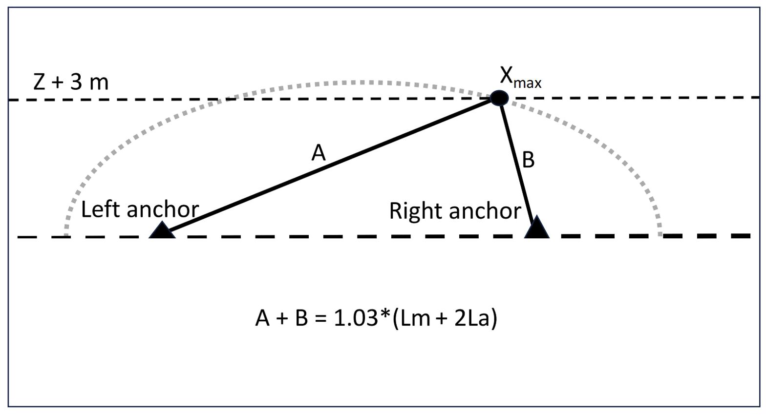
Figure 6. Basic assumptions of the simplified model used to determine the percentage of the ML that can be raised 3 m above the sea surface with a 3% elongation of the lines. Z is the water depth. The dotted gray curve is the half ellipse whose foci are the two anchors and the set of points are such that the sum of the distances to the foci (A + B) is equal to the total length of the stretched ML (Lm) and the two mooring lines (2La). The leftmost point of the LL that can be brought 3 m above the sea surface is denoted Xmax.
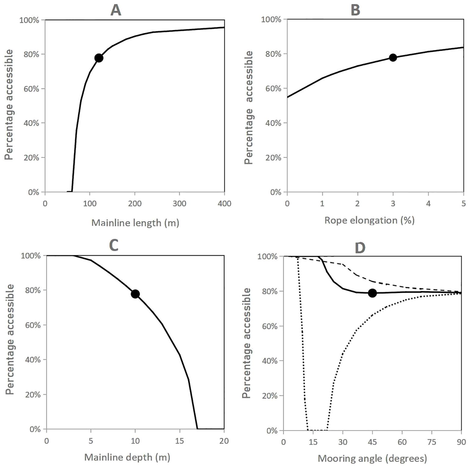
Figure 7. Effect on the percentage of the mainline accessible from the surface of changing (A) mainline length, (B) rope elongation, (C) mainline depth, and (D) mooring angle. The black dot is the standard longline (Table 3). In (D), results are for a rope elongation of 1% (dotted line), 3% (full line) and 5% (dashed line).
To sum up the above, ML depth control for surface and semi-submerged LLs is relatively easy because there are many supports with reserve buoyancy along the mainline (small sag), these serve as direct visual clues on the need to adjust the buoyancy and, in the case of surface LLs and kelp LLs, there is relatively easy access to the ML to make this adjustment. It is more difficult for fully-submerged LLs (no direct visual clues and limited access to ML) and it is critical for those without legs because there is no place to install any buoyancy reserve along the ML and, consequently, the buoyancy must be adjusted frequently to limit the sag in the ML. If the ropes have a reasonable stretch under safe lifting forces and these can be higher than 10 kN, increasing the mooring line length (increasing the scope) will increase the accessibility of the ML from the sea surface, increase the pretension in the mainline and decrease the potential sag in the ML. However this will be at the expense of a larger LL footprint. A compromise will likely be necessary if space is limited in the leased area.
4.2 Tidal sea surface elevation
On surface and semi-submerged LLs, variations in sea surface elevation (SSE) caused by tides produces large variations of the tension in the lines. This is caused by variations in the submergence of the surface buoys. Plew (2005), Plew et al. (2005), Stevens et al. (2007), Nguyen et al. (2019), Zhu et al. (2019) and Moscicki et al. (2024) observed that the mean forces generated on this type of LL in mesotidal sites were mostly due to tidal SSE. In macrotidal sites the tension in the ML may become high enough at high tide to render lifting operations difficult and low enough at low tide that the ML becomes slack with large sags and increased wave effect on the suspensions (Bompais, 1991). One way of reducing the effect of SSE is the use surface spar (pencil) buoys. Indeed, for the same nominal buoyancy and SSE, the increase of the effective buoyancy of spar buoys is much less than that of spherical and elliptical buoys. Another way is to add tensioner buoys on the mooring lines. In the case of fully submerged LLs the effect of SSE is negligible because it does not increase the effective buoyancy of the floats (Gagnon and Bergeron, 2017).
4.3 Steady currents
Steady currents are generally assumed to be purely horizontal. They exert on LL components a horizontal force in the direction of the current (hereafter called the “drag”) and a vertical force directed towards the sea surface (“uplift”) or towards the sea bottom (“downlift”). On a typical LL, the cultured biomass and the structures to which it is attached or in which it is contained represent up to 90% of the total LL drag area, volume and mass. Consequently, forces acting on the LLs mainly depend on those exerted on the suspensions. The latter are reviewed first before reviewing the effect on whole LLs in the next section.
4.3.1 Effect on LL suspensions
In the cases of the mussel dropper and scallop lantern net, an analytical numerical model developed by Raman Nair et al. (2008) was used to simulate the effect of steady currents on these two types of suspensions (Figure 8). Both suspensions gradually incline with increasing current velocity. The mussel dropper attains a 45° inclination from vertical at a current velocity of 0.53 m/s (Figure 8A) and this produces an uplift (Figure 8C) corresponding to 40% of the buoyant weight of the dropper (Figure 8D). In the case of the lantern net, a 45° inclination is attained at 0.37 m/s and the uplift corresponds to 43% of the lantern net’s buoyant weight.
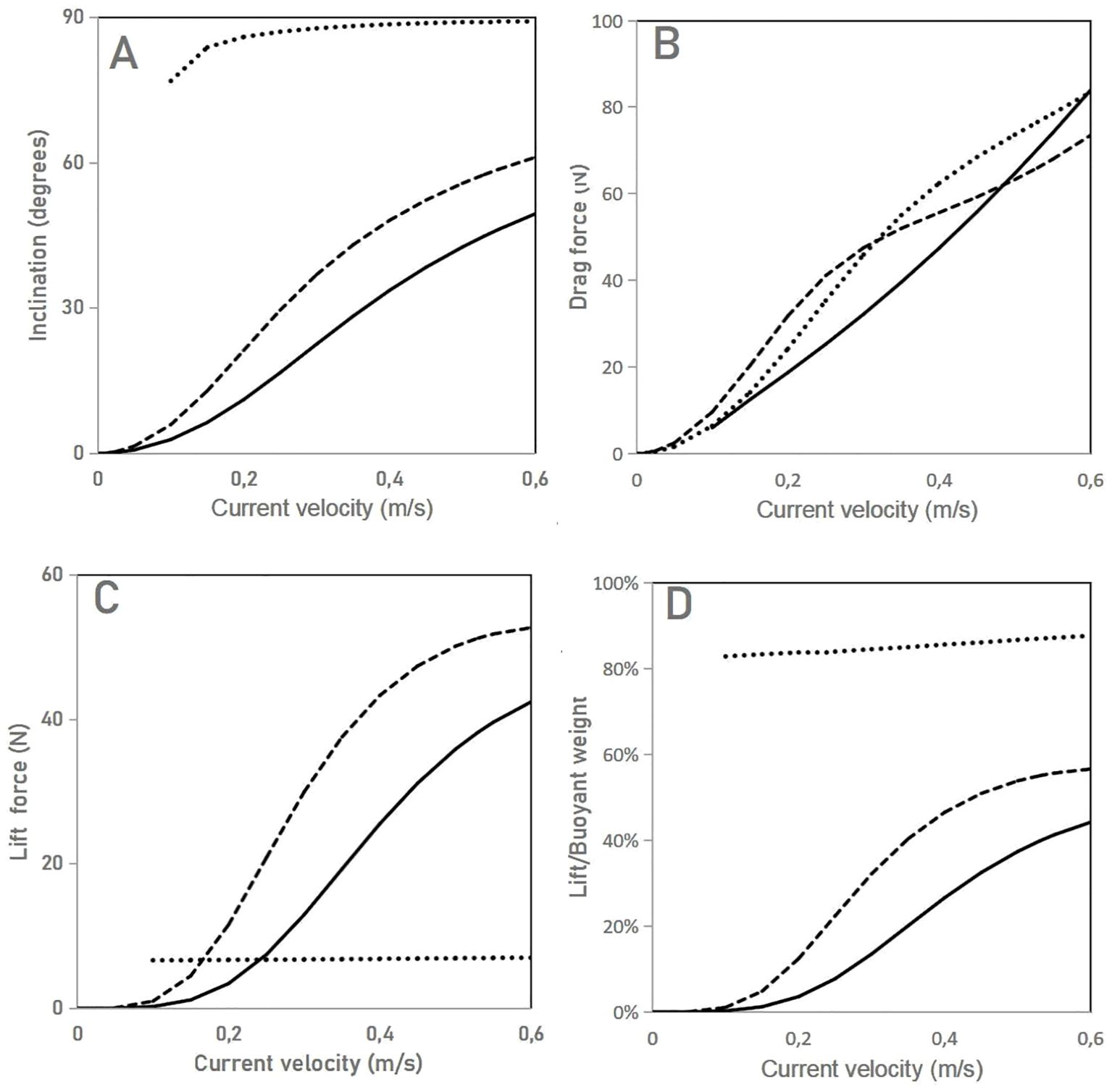
Figure 8. Effect of steady currents on individual suspensions. (A) Inclination of the suspensions; (B) drag force on the suspensions; (C) lift force on the suspensions; (D) lilt force on the suspensions as a percentage of their buoyant weight. Full line: mussel dropper; dashed line: scallop lantern net; dotted line: horizontal kelp line.
In the case of the horizontal kelp-line, the results presented in Figure 8 come from the relationship established by Endresen et al. (2019) between the drag force, plant length, kelp weight and current velocity for full-scale live 3 m long kelp-line segments in perpendicular currents and from Lei et al. (2021) observations on the inclination and reconfiguration in steady currents of full-scale live kelp-line segments similar to the case study. The kelp blades attain a nearly horizontal posture in steady currents of more than 0.1–0.2 m/s. Above this threshold, in a cross-sectional view, the kelp-line resembles a streamlined body whose upstream (frontal) part is formed by the stipes that bend around the rope in the current direction and the downstream (distal) part is formed by the blades oriented parallel to the current direction. With increasing current velocity, the height of the stipe bundle decreases and the blades adopt a more streamlined shape. Due to this reconfiguration, the drag force on the kelp-line is not proportional to the current velocity squared (U2) as in the case of a flat plate but rather to roughly U1.4. In this example, the uplift corresponds to more than 85% of the kelp’s buoyant weight at velocities > 0.3 m/s. The fact that the current exerts a drag force of similar magnitude on all three study cases (Figure 8B) is a coincidence in the choice of the suspension characteristics. Steady currents exert on kelp-lines a much smaller lift force than on heavy suspensions (mussel droppers and lantern nets; Figure 8C). In response to the lift force the buoyant weight of mussel droppers and lantern nets do not allow full reorientation parallel to the current direction seen with the kelp-line. This force changes the delicate balance between the installed buoyancy and the buoyant weight of the cultured biomass and fouling (see Section 4.3.3).
In the case of the floating vertical kelp-line at rest it resembles a wide and rough cylinder with the blades hanging downward parallel to the kelp-line axis (Bak et al., 2020). As the current velocity increases to 0.1–0.2 m/s, the kelp biomass adopts the same posture and streamlined shape around the rope as described above for the horizontal kelp-line and the kelp-line itself adopts a curved posture due to the presence of a float at the top end (Lona et al., 2020). As in the case of the mussel dropper and lantern net, the mean inclination of the kelp-line increases with increasing current velocity, but this time the inclination is towards the bottom and, if the buoyancy of the float is just enough to compensate the buoyant weight of the kelp at harvest, the kelp-line at that time will tend to be horizontal (at the depth of the mainline) at current velocities > 1.0 m/s.
4.3.2 Effect on complete longlines
The force exerted by steady currents on isolated LLs depends on their angle of attack (0° when parallel to the anchor axis). In the case of the force transmitted to the mooring lines and anchors, two factors are in play: the shielding effect and the LL deflection effect.
4.3.2.1 Shielding effect
In currents parallel to the LL, the bulk drag force on the ML is usually lower than the sum of the forces on the individual isolated suspensions because there is a strong fluid-suspension interaction that reduces the velocity of the current acting on downstream suspensions (Plew, 2005; Plew et al., 2005; Gagnon and Bergeron, 2017). The importance of this shielding (sheltering, shadowing) effect depends on the angle of attack (minimum when the current is perpendicular and maximum when parallel) and the suspension spacing ratio (distance between the suspensions divided by their diameter). This effect is very difficult to measure in-situ due to many confounding factors (Gagnon and Bergeron, 2017) or on large scale physical models in current flumes because the latter are not wide enough. With a few exceptions (Lopez et al., 2017), published numerical simulations ignore this effect.
To illustrate the complexity and importance of the shielding effect for LLs with mussel droppers and lantern nets I use here the results of flume tests on rows of rigid fixed smooth cylinders carried out by Plew (2005) and Fredheim (2005). A spacing ratio of 2.2 representative of a LL with the fouled lantern nets was used in the case of Plew’s tests and of 5.0 representative of a LL with mussel droppers was used in Fredheim’s tests. The results of these tests are presented in Figure 9A where the shielding effect is given as a function of the current angle of attack and is expressed as the ratio of the measured bulk drag force on the row of cylinders to the maximum drag force (Fbk/Fmax; %) that would be exerted if there was no shielding (drag on a single isolated cylinder multiplied by the number of cylinders in the row). For the closely spaced cylinders, the relationship adopts the form of a sine curve where the shielding effect gradually decreases as the angle of attack increases. In the case of the larger spacing the shielding effect is lower in a parallel current than in the case of the closely spaced cylinders and decreases with increasing angle of attack up to 30° then remains nil up to 90°. According to these exploratory results, there would be a strong shielding effect on mussel LLs only for small angles of attack while the shielding effect would be much stronger on LLs with lantern nets spaced 1 m apart.
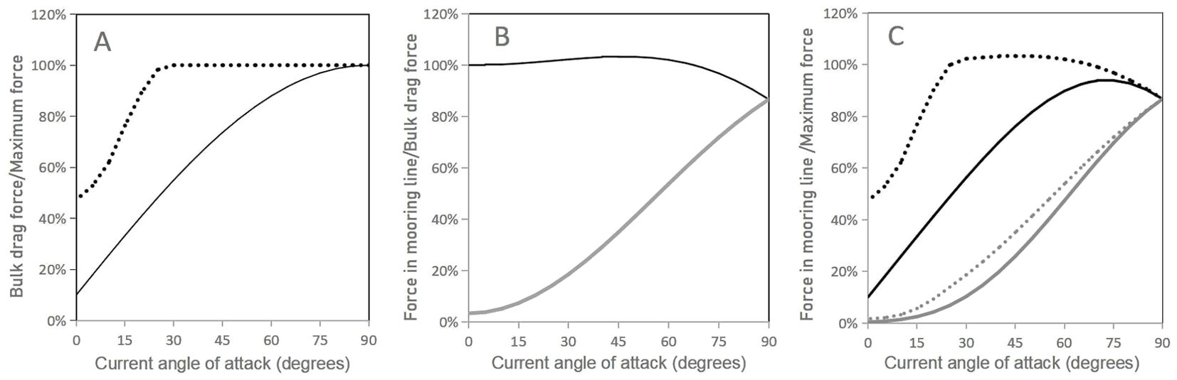
Figure 9. (A) Shielding effect: measured bulk drag force on the mainline (Fbk) as a percentage of the force that would be exerted if there was no shielding effect (Fmax) as a function of the current angle of attack (0° when parallel to the anchor axis). (B) LL deflection effect: percentage of the bulk drag force on the ML (Fbk) that is transmitted to each mooring line (Fmo) as a function of the current angle of attack. (C) Combined effect: measured drag force transmitted to each mooring line (Fmo) as a percentage of the force that would be exerted on the ML if there was no shielding effect (Fmax) as a function of the current angle of attack. In (A) and (C): full lines: suspension spacing ratio = 2.2; dashed lines: suspension spacing ratio = 5. In (B) and (C): black lines: upstream mooring line; gray lines: downstream mooring line.
The case of the horizontal kelp-line in a perpendicular current was covered in Section 4.3.1. When parallel to a current stronger than 0.1–0.2 m/s, the kelp mass in a side view of the kelp-line likely resembles a thick and rough cable the diameter of which decreases as the current velocity increases (Lei et al., 2021). Since the drag area of the kelp mass in this posture is much smaller than when the current is perpendicular, it is also likely that there is a large shielding effect on horizontal kelp-lines. In the case of fully grown floating vertical kelp-lines (Bak et al., 2018) in a parallel current higher than 0.1–0.2 m/s, the kelp mass in a side view of the kelp-line resembles in-line flags. The wetted area of the kelp mass in this posture is not significantly different than when the current is perpendicular but the pressure drag on the frontal part of the kelp-lines is likely less for low angles of attack as in the case of mussel droppers.
4.3.2.2 Longline deflection effect
When a LL without legs is parallel to the current all the bulk drag force on the ML is transmitted to the upstream anchor and when it is perpendicular it is split evenly between the two anchors. However, the perpendicular current causes a horizontal deflection of the center of the LL in the direction of the current and the total force on each anchor is larger than half the bulk drag force on the ML. Contrary the the shielding effect, this effect is well captured by numerical simulations (Fredheim and Lien, 2001; Buck et al., 2017; Dewhurst, 2019; Cheng et al., 2020). It is illustrated in Figure 9B for a longline with a deflection ratio of 0.19 (deflection distance/distance between anchors) as a function of the current angle of attack. It is expressed as the ratio (%) of the force in each mooring line to the bulk drag force on the ML (Fmo/Fbk; %). The force on the upstream anchor is higher than the bulk drag force on the ML for angles of attack between 15° and 67° and, when the current is perpendicular to the anchor axis, the force on both anchors is the same but is more than half (87%) the bulk drag force.
4.3.2.3 Combined effect of the current angle of attack
Figure 9C combines the shielding and deflection effects as a function of the current angle of attack for a deflection ratio of 0.19 and is expressed as the ratio of the force in each mooring line to the maximum force (Fmo/Fmax; %). It shows that in currents parallel to the anchor axis the force on the upstream anchor for the LL with closely spaced suspensions is only 10% of what the force would be if there was no shielding and that the maximum force on this anchor is attained at an angle of attack of 75°. For the LL with more spaced suspensions, the force on the upstream anchor is much higher at all angles of attack and is maximum at a 45° angle of attack.
The presence of legs on the mainline completely changes the relationships shown in Figure 9. Indeed, in oblique and perpendicular currents the legs limit the horizontal deflection of the mainline and resist a large part of the bulk drag force (Gagnon and Bergeron, 2017). Although the relationships in Figure 9 are just approximations, they show that orienting LLs parallel to the main current axis will reduce the probability that they experience large hydrodynamic forces. This is currently the practice adopted in most commercial farms (Gagnon, 2024).
4.3.3 Effect on mainline depth
One of the main objectives of LL design and husbandry operations is to maintain the ML depth within a narrow window (design depth). Steady currents affect the depth of the ML in several ways, depending on the type of LL, its orientation relative to the current direction and the type of suspension. In the case of LLs without legs in a current parallel to the anchor axis, the tension in the mainline increases from the downstream end towards the upstream end of the ML. This tends to deflect the ML downstream, decreases the mooring angle at the upstream end of the ML and increase it at the downstream end and creates a positive slope in the ML from the upstream to the downstream end. If the corner buoys are at the surface, the submergence of the upstream one will increase and that of the downstream one will decrease. The reserve buoyancy of the upstream buoy will limit the slope in the ML. If the corner buoys are submerged, the depth of the upstream buoy will increase and that of the downstream buoy will decrease and the slope in the ML will be more pronounced than with surface buoys. If the mooring lines are longer than the water depth, the downstream corner buoy will reach the sea surface. Furthermore, the uplift exerted by currents on mussel droppers and lantern nets (see Section 4.3.1) may lift the downstream part of the ML up to the sea surface if the submerged buoyancy on it is too high (Langan et al., 2010; Dewhurst, 2019; Boo et al., 2023). These situations must be avoided for many reasons including increased risks of navigational and marine mammal entanglement and increased wave forces on the downstream part of the ML. To eliminate this problem the total buoyancy of the submerged compensation buoys must not exceed the total buoyancy (surface + submerged) required to compensate the total buoyant weight on the ML minus the expected uplift force on the suspensions for the design current velocity. In the case of the semi-submerged mussel longline studied by Dewhurst (2019), the submerged buoyancy not to exceed corresponded to 67% of the total required buoyancy, with a minimum of 33% of the required buoyancy placed in the surface buoys. On fully submerged LLs without legs where 100% of the buoyancy is submerged, ML uplifting by currents cannot be avoided for LLs with mussel droppers or lantern nets (Langan et al., 2010; Dewhurst, 2019). However, if legs are added along the ML with sufficient buoyant weight of the sinkers (Raman Nair et al., 2008), the slope in the mainline will be limited to the upstream part of the mainline while the rest of the mainline will stay at the design depth (Figure 10A).
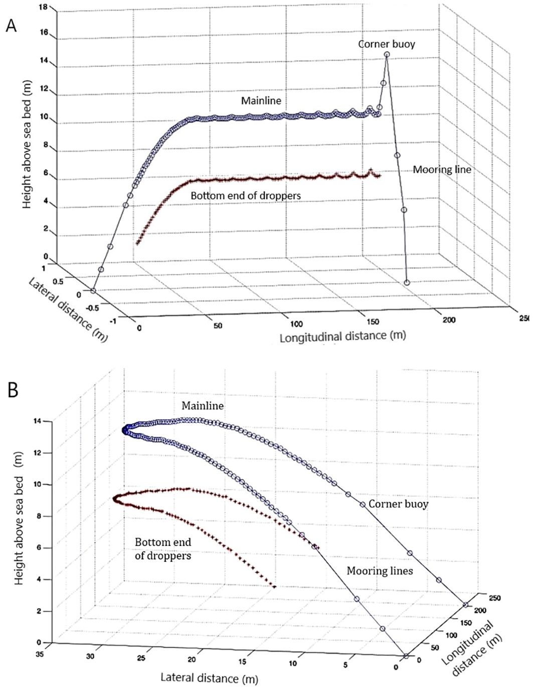
Figure 10. Three-dimensional posture of a typical fully submerged mussel longline with 11 m long legs in a steady current parallel to the anchor axis (A) and perpendicular to the anchor axis (B). Site depth is 21 m. Only the mooring lines, mainline and bottom end of the mussel droppers are represented. Not to scale.
In a current perpendicular to the anchor axis, the ML is deflected horizontally in the direction of the current and adopts the shape of a catenary in a top view (Grosenbaugh et al., 2002; Fredheim and Lien, 2001). The tension in the ML increases from the center towards both ends. The increased tension at both ends reduces the mooring angle and increases the depth of both ends of the ML unless there are surface corner buoys with sufficient reserve buoyancy to counteract this effect. The uplift on the suspensions tends to lift the middle part of the ML towards the surface unless there are legs on the ML as shown in Figure 10B. In the case of LLs with floating vertical kelp-lines in parallel and perpendicular currents, the downlift on the suspensions prevents the lifting of the ML to the surface and tends to incline the suspensions towards the bottom (Lona et al., 2020).
4.3.4 Interactions with whole farms
The interaction between steady currents and LL farms has been the object of several studies (Supplementary Table S1C). Generally, the velocity of an unidirectional steady current will be reduced at its passes through the farm as part of the flow is redirected above, below and/or on both sides of the farm. For a given type of suspension, the importance of this reduction depends on the areal density (number/ha) and vertical distribution in the water column of the suspensions and on LL orientation relative to the current. Shellfish farms in exposed sites have a relatively low density; they are arranged in rows of several in-line LLs, with 25 to 50 m between parallel rows (Gagnon, 2024). Orienting the rows perpendicularly to the flow results in a greater attenuation of currents inside the farm and therefore a greater reduction of seston and nutrient supply to the farm as a whole than orienting them parallel to the flow. However, in the latter case the flow is concentrated in the channels between the rows of LLs while the shielding effect between the droppers locally reduces the flow around the droppers. In most farm sites currents are tidal and reverse every 6 hours and they are seldom uni-directional in exposed sites (Gagnon and Bergeron, 2017; Dewhurst, 2019). According to Plew (2005), the natural variability of flow direction is likely to be sufficient to ensure an adequate supply to all suspensions when placing LLs parallel to the main current axis. For a large and low density farm, the advantages of aligning the LLs at low angles to the dominant currents, reducing the interference between LLs, should outweigh any shielding effect between individual droppers on individual LLs. However, more research is required to confirm this statement.
5 Dynamic analysis
5.1 Effect of wind seas and swells on isolated longlines
Wind seas are generated locally and their energy depends on the fetch of the site in the direction from which the wind is blowing while large swells are generated by storms that pass far from the site. The effect of wind seas and swells on LLs is very complex due to the confounding effect of several factors including the wave type (regular or irregular), wave height, wavelength and orientation and the presence or absence of currents and their orientation relative to the waves. Furthermore, waves exert not only a drag force but also an inertia force cause by the acceleration of the fluid around the LL components. In this section I review the effects of LL design and buoyancy management on the loading of the windward mooring line and the motion of the buoys and suspensions. But first, the wave shielding effect must be addressed.
5.1.1 Longline orientation and wave shielding
Tests on a surface LL model parallel to wave propagation in a wave flume by Cheng et al. (2023) show that there is a significant wave shielding effect that depends on the wavelength; it is small for low frequency waves (swells) and large for high frequency waves (wind seas). These authors did not test other angles of attack. To my knowledge, in-situ observations and physical model tests in wave tanks have not addressed the effect of LL orientation on wave loading. However, this effect was studied using numerical simulations by Deng et al. (2010), Zhang et al. (2015), Lopez et al. (2017), Cheng et al. (2020), Davonski (2020) and Feng et al. (2021). Contradictory results were obtained where the maximum tension on the windward mooring line increases or decreases with increasing angle of attack or is maximum in oblique waves. This is likely due to the fact that the numerical models used do not include a wave shielding effect. Plew (2005) and Plew et al. (2005) observed that the attenuation of waves as they propagated perpendicularly to the LLs in a large (650 m wide; 22 LLs across) low density (600 droppers/ha) farm depended on their wavelength: small waves (period< 5 s) were more attenuated than large waves for which attenuation was less than 10%. Zhu et al. (2020) came to the same conclusion using numerical simulations of a 200 m wide and more dense (1,250 droppers/ha) mussel farm during a large storm; the farm reduced the incident wave energy by more than 60% for 3 s period waves and by less than 15% for 20 s period waves.
The above indicates that high frequency waves interact more with the LLs than swells. It can only be speculated that, in the case of an isolated LL, there is a significant wave shielding effect that depends on dropper spacing when it is placed parallel to the prevailing direction of fetch-limited waves and that this effect is minimal for a 90° angle of attack. For a block of several LLs there would be a shielding effect for high frequency waves at all orientations while for large swells the shielding effect would be small for all orientations. If this proves correct, the orientation of LLs relative to waves in exposed sites would be less important than their orientation to storm generated currents.
5.1.2 Effect of mainline depth
Generally, the force exerted by waves on LL components decreases with increasing depth. For example, for waves of 2 m height and 40 m wavelength in 25 m water depth, the forces on a bluff body at 10 m will be 25-fold less than at the surface (Bompais, 1991). This reduction was verified by numerical simulations for semi-submerged scallop and mussel LLs and a kelp submersible array (Lopez et al., 2017; Dewhurst, 2019; Lian et al., 2023) and mussel semi-submerged and fully submerged LLs (Smeaton, 2019). The comparison of in-situ observations of surface and fully submerged mussel LLs (Gagnon and Bergeron, 2017) shows that the maximum vertical acceleration of the droppers in the latter case is one order of magnitude less than for surface LLs. Thus, to minimize wave forces, ML depth on shellfish LLs should be maximized while in the case of kelp-lines that must remain in the photic zone, the floating vertical kelp-line is the design that will minimize wave forcing.
5.1.3 Effect of mainline length
Tests on physical LL models in wave flumes (Matsubara et al., 1985, 1990; Zhao et al., 2019; Cheng et al., 2023; Wang et al., 2023) show that the loading and motion of LLs parallel to wave propagation depend on the ratio of the ML length to wavelength (Lm/λ). Maximum tension in the windward mooring line increases with increasing wave height but the relationship with the wavelength (period) is complex and not fully understood. Cheng et al. (2023) tested Lm/λ ratios between 0.59 and 1.93. Incorporating the shielding effect in their numerical model simulations, the maximum tension in the windward mooring line was largest for Lm/λ ratios between 1.15 and 1.35. It was concluded that to minimize the loading of the windward mooring line in waves parallel to the LL, a ML length between 1.15 and 1.35 times the wavelength of the design wave should be avoided. This result is likely due to how the forces along the ML act in the same or opposite directions as suggested by Stevens et al. (2007). According to Cheng et al. (2023) most part of the force transmitted to the windward mooring line is caused by the submersion of the surface buoys. In the case of a fully submerged LL without legs (Matsubara et al., 1990), tension in the mainline did not vary significantly for a Lm/λ range of 0.4 to 2.0. This is likely because the effective buoyancy of submerged buoys is not affected by waves.
The tests carried-out by Zhao et al. (2019) and Wang et al. (2023) on surface and semi-submerged LLs parallel to wave propagation and in ranges of the Lm/λ ratio of 0.8 to 1.25 and 1.7 to 5.0, respectively, show that the amplitude of the horizontal and vertical displacement of the surface buoys and lantern nets decreases with increasing Lm/λ ratio and is lower than the wave height for ratios > 1.0. They explain this result by the fact that the tension in the lines increases with increasing Lm/λ ratio and high tension in the ML constrains the displacement of the suspensions (Boo et al., 2023). Finally, in tests on a fully submerged LL without legs parallel to wave propagation with a range of Lm/λ ratios between 0.4 and 2.0 Matsubara et al. (1985) found that the maximum vertical displacement of the buoys was highest (and higher than wave height) for ratios of 0.8 to 1.4. To sum up the above, in order to minimize the loading of the mooring lines and the vertical displacements of the suspensions on a LL parallel to wave propagation, the length of the ML should be at least 1.4 times the wavelength of the design waves.
5.1.4 Effect of buoy size, shape and placement
Lee et al. (2014) have studied in a wave flume the effect of steady currents and waves on tethered surface buoys of various shapes. Steady currents exerted more tension in the tether line in the case of long cylinders moored vertically (pencil floats, spar buoys) than for spherical floats. However, the contrary was observed for the forces exerted by waves. This is because spherical floats ride the waves while pencil floats are less sensitive to sea surface elevation (Bompais, 1991). The worst shape tested by Lee et al. (2014) was a low-aspect cylindrical buoy moored horizontally similar to the buoys used on double backbone surface LL (Plew et al., 2005).
Lien and Fredheim (2001) compared with numerical simulations two types of surface mussel growing structures: a conventional LL with pencil floats and a horizontal longtube. In waves parallel to the LLs, there were snap loads in the dropper lines of the conventional LL while in those attached to the longtube the tension was much less variable and no zero tensions were recorded. In small waves, snap loads were seen in droppers directly under the buoys while in large waves they were seen in the droppers placed in the middle of the span between the buoys. In waves perpendicular to the LL, the span between the floats and the droppers attached to it show large accelerations as the ML stretches and un-stretches at each passing wave while this effect is not possible with the longtube. This shows that, for the same total buoyancy, placing several small buoys on the ML is a better approach for surface LLs than a few large floats (Bompais, 1991).
Snap loads in the suspensions are responsible for mussel drop-off from fully grown mussel droppers and reduced growth and survival of scallops grown in lantern nets. These are caused by the out of phase motion of the buoys and suspensions. At each passing wave, the tension in the dropper line can go down to zero as the wave through passes and suddenly increase in the ascending phase of the wave (Bompais, 1991). For surface and semi-submerged LLs, the risk of snap loads can be reduced by 1) increasing the tension in the ML, 2) preventing surface buoys from having too much reserve buoyancy (by frequent buoyancy adjustments), 3) limiting the span between the buoys (many small floats better than smaller number of large floats) and 4) using pencil floats rather than spherical ones (Bompais, 1991; Lien et al., 2001). In the case of fully submerged LLs snap loads are less likely due to the reduced wave loading and absence of forces caused by buoy submergence.
5.1.5 Effect of adding legs
The only study on the effect of adding legs on wave loading of fully submerged LLs is that of Knysh et al. (2020). They simulated the effect of adding three legs to a fully submerged mussel LL in extreme waves and currents perpendicular to the anchor axis. When compared to the LL with the same geometry without the legs, the maximum vertical acceleration of the droppers increased by 24%. According to Loste and Cazin (1993) adding legs to a LL decreases its structural flexibility and increases the risk of snap loads in the suspensions.
5.1.6 Effect of mooring configuration and angle
Mooring lines can be designed in many different configurations. For a thorough review of those most often used on LLs see Bompais (1991) and Priour (1995). Most of the commercial farms that are currently operating in exposed sites use the most simple configuration: a single taut rope (Gagnon, 2024). Some use a tensioner mooring with one submerged buoy attached to the mooring line at some distance between the anchor and corner buoy. The disadvantage of the single-leg mooring is that it is less effective in damping wave energy than the chain catenary mooring and the tensioner mooring. The chain catenary mooring is more expensive and requires a much larger distance between the anchors than the other mooring configurations and are not used when lease space is limiting. The latter reduces the dynamic range of the mooring force on the condition that the tensioner buoy remains submerged in all conditions (Palm and Eskilsson, 2020).
Cheng et al. (2023) studied the effect of increasing the mooring line angle from 19° to 45° (decreasing mooring line length, scope) on a surface LL with a simple taut mooring line in waves parallel to the LL. This caused a decrease of the maximum tension in the windward mooring line. This is likely because the pretension in the mainline decreased with increasing mooring angle.
6 Discussion and conclusion
Although LLs are relatively simple and inexpensive structures, their interaction with currents and waves is complex and they should be carefully designed before deployment in high energy environments. The simple analytical models presented in this paper were used only to illustrate this complexity and the many compromises that must be made. Site surveys to collect metocean data and more complex and suitable models based on finite element analysis (FEA) must be used to properly design LLs for exposed sites. However, simulations that ignore the current and wave shielding effects provide over-estimations of the loading and motion of LLs in many situations.
While it is standard practice to multiply by safety factors the estimated maximum forces to determine the dimensions of LL components such as anchors and ropes, this is not applicable to buoys/floats. Buoyancy management requires to maintain a delicate balance between the buoyancy of the floats and the time varying buoyant weight of the cultured biomass and fouling. Over-sizing buoys compromises the survivability of the structure and the survival (retention), growth and quality of the cultured biomass. The best way to reduce the hydrodynamic loading and agitation of LLs by waves is to maintain the ML at the largest depth possible. That depth can be considerable for bivalves but not for kelp which must remain in the surface illuminated layer at least during day time. In the case of the floating giant kelp (Macrocystis sp.) the ML can serve as the kelp-line and the plants float naturally above it (Tullberg et al., 2022) while in the case of kelp species with negative buoyancy (S. latissima and S. japonica), a promising method consists of growing then on vertical lines fitted with a small float at the top end. This way the ML can be lower in the water column and the downlift exerted by currents on the kelp-lines will push the kelp biomass out of the surface layer during storms.
Lowering the ML in the water column comes at the expense of reducing the percentage of the ML accessible from the surface (or increasing the size of the lines, the holding power of the anchors and the size of the vessels required for this operation). It also complicates considerably buoyancy management in the case of fully submerged LLs. Buoyancy management becomes problematic on fully submerged LLs without legs because there is no place to install a buoyancy reserve on the ML. To maintain the ML at the design depth frequent buoyancy adjustments are required and these may be costly and impossible for considerable periods of time. Lifting frequently the ML can also affect the survival (retention) and growth of the cultured biomass. An interesting design is to install all the buoyancy required until harvest at the beginning of the grow-out cycle so that adjustments are not required (i.e. the “set and forget” approach). This is possible by adding legs on fully submerged LLs but this increases considerably the forces required to lift the ML to the surface at harvest. A new concept developed in New Zealand eliminates this problem by clamping the ML to fixed legs with a special device that releases it on command from the surface for servicing and harvesting (Goseberg et al., 2017). Other concepts being tested are based on depth cycling using variable buoyancy components (submersible buoys). This cycling can be diurnal (for kelp), occasional (lowering at the approach of a storm, lifting for husbandry and harvesting operations), seasonal (lowering during winter or predatory duck migration). It is likely that this approach can eventually become economically feasible only for large arrays of LLs (Bale, 2017; Goseberg et al., 2017; Capron et al., 2018; Godsiff, 2020; Navarette et al., 2021; Kite-Powell et al., 2022; Lian et al., 2023, 2024).
LL orientation relative to currents and waves determines in large part the intensity of their loading and motion and the seston or nutrient flux through the farms. It is also important for determining the area efficiency of the farm within an allocated lease. In sheltered sites, LL loading by currents is larger than by waves and, in most commercial sites, LLs are oriented parallel to the tidal current axis to minimize the drag forces. However, there is presently no consensus on what should be their orientation in exposed sites where current and wave loading are both important and multi-directional. In some exposed farms the LLs are oriented parallel to the prevailing direction of swell propagation and in others they are parallel to the main axis of the currents as determined from long-term recordings (Gagnon, 2024). Up to now, in-situ measurements, physical models tested in current and wave flumes and numerical models have not been able to resolve this important question. In the former case, there are many confounding factors that mask the effect the current and wave angle of attack. In the case of flume tests, the flumes are not wide enough to test LLs in oblique and perpendicular currents and waves. Finally, numerical models do not incorporate current and wave shielding as a function of suspension spacing and current/wave angle of attack because these relationships are unknown; the simulations ignore these effects or apply estimated reduction coefficients to the current velocity field or drag coefficients. It is likely that the loading and motion of LLs are very sensitive to their orientation relative to steady currents and small waves and much less sensitive to their orientation relative to large waves (swells) but more research is required to confirm this. If confirmed, it would mean that the LLs should be oriented parallel to the main direction of storm generated currents, hence the need for reliable metocean data for each site.
LL design and farm layout are not conditioned only by mechanical considerations. Other important economic, environmental and social considerations come into play including scalability (Solvang et al., 2021; St-Gelais et al., 2022), ease of mechanization and automation of seeding and harvesting operations (Chung et al., 2015; Choi, 2020; Capron et al., 2018; Solvang et al., 2021), co-location with renewable energy infrastructure (Buck and Langan, 2017), remote sensing (Myamoto et al., 2020; Peres da Silva, 2021), marine mammal entanglement (NOAA, 2015; Bath et al., 2023; ICES, 2023) and human health & safety (Yang et al., 2020). Several research and development programs currently underway around the world to test new LL design and operation (see a listing in Gagnon, 2024) will increase considerably the knowledge base supporting aquaculture expansion to exposed sites.
Author contributions
MG: Conceptualization, Formal analysis, Investigation, Methodology, Writing – original draft, Writing – review & editing.
Funding
The author(s) declare that no financial support was received for the research, authorship, and/or publication of this article.
Acknowledgments
The author wishes to thank two reviewers for their helpful comments and suggestions.
Conflict of interest
Author MG was employed by Biorex Inc.
Publisher’s note
All claims expressed in this article are solely those of the authors and do not necessarily represent those of their affiliated organizations, or those of the publisher, the editors and the reviewers. Any product that may be evaluated in this article, or claim that may be made by its manufacturer, is not guaranteed or endorsed by the publisher.
Supplementary material
The Supplementary Material for this article can be found online at: https://www.frontiersin.org/articles/10.3389/faquc.2024.1422173/full#supplementary-material
References
Bak U. G., Mols-Mortensen A., Gregersen O. (2018). Production method and cost of commercial-scale offshore cultivation of kelp in the Faroe Islands using multiple partial harvesting. Algal. Res. 33, 36–47. doi: 10.1016/j.algal.2018.05.001
Bak U.G., Gregersen Ó., Infante J. (2020). Technical challenges for offshore cultivation of kelp species: lessons learned and future directions. Bot. Mar. 63 (4), 341–353. doi: 10.1515/bot-2019-0005.
Bale E. S. (2017). Development of area-efficient and standardized structures for large-scale macroalgae cultivation. SINTEF Rep. OC2017A171. 24, ISBN: ISBN: 978-82-7174-310-9.
Bannister J., Sievers M., Bush F., Bloecher N. (2019). Biofouling in marine aquaculture: a review of recent research and developments. Biofouling 35, 631–648. doi: 10.1080/08927014.2019.1640214
Bath G. E., Price C. A., Riley K. L., Morris J. A. Jr. (2023). A global review of protected species interactions with marine aquaculture. Rev. Aquac. 15, 1686–1719. doi: 10.1111/raq.12811
Bergeron P., Gagnon M. (2003). Description, analyse et modélisation des filières flottantes utilisées pour l’élevage de mollusques au Québec Vol. 2003 (SODIM Rep), 367.
Bonardelli J. C. (1996). “Longline shellfish culture in exposed and drift-ice environments,” in Proc. Open Ocean Aquaculture Int. Conf. 1996, Portland, Maine. 235–252.
Boo S. Y., Shelley S. A., Shin S.-H., Park J., Ha Y.-J. (2023). Design and analysis of a sub-surface aquaculture farm for co-existence with offshore wind farm. J. Mar. Sci. Eng. 11, 1034. doi: 10.3390/jmse11051034
Buck B. H. (2007). Experimental trials on the feasibility of offshore seed production of the mussel Mytilus edulis in the German Bight: installation, technical requirements and environmental conditions. Helgoland Mar. Res. 61, 87–101. doi: 10.1007/s10152-006-0056-1
Buck B. H., Bjellan H. V., Bockus A., Chambers M. D., Costa-Pierce B. A., Dewhurst T., et al. (2024). Resolving the term «offshore aquaculture» by decoupling «exposed» and «distance to coast». Front. Aquac. 3. doi: 10.3389/faqc.2014.1428056
Buck B. H., Krause G., Pogoda P., Grote B., Wever L., Goseberg N., et al. (2017). “Case study German Bight: pioneer projects of aquaculture-wind farm multi-uses,” in Aquaculture Perspective of Multi-Use Sites in the Open Ocean: The Untapped Potential for Marine Resources in the Anthropocene. Eds. Buck B. H., Langan R. (Springer, Cham), 253–354.
Buck B. H., Langan R. (2017). Aquaculture perspective of multi-use sites in the open ocean: the untapped potential for marine resources in the anthropocene (Berlin/Heidelberg, Germany: Springer).
Capron M. E., Blaylock R., Lucas K., Chambers M. D., Stewart J. R., DiMarco S. F., et al. (2018). “Ocean forests: breakthrough yields for macroalgae,” in Proceedings of the OCEANS 2018 MTS/IEEE Charleston, Charleston, SC, USA, 22–25 October 2018. 1–6. doi: 10.1109/OCEANS.2018.8604586
Cheng W., Sun Z., Liang S., Liu B. (2020). Numerical model of an aquaculture structure under oscillatory flow. Aquac. Eng. 89, 102054. doi: 10.1016/j.aquaeng.2020.102054
Cheng W.-W., Xu Y.-Y., Mu P. (2023). Experimental and numerical investigation of the dynamic responses of longline aquacultural structures under waves. Ocean Eng. 276, 114234. doi: 10.1016/j.oceaneng.2023.114234
Choi K.-J. (2020). Development of the automation system for seaweed biomass mass production. J. Korean Soc Ind. Converg. 23, 351–359. doi: 10.21289/KSIC.2020.23.2.351
Chung H., Kim N. G., Choi K. J., Woo H. C. (2015). “Novel ocean system for high density mass production of seaweed biomass in Korea,” in 2015 World Congress on Advances in Structural Engineering and Mechanics (ASEM15), Incheon, Korea, August 25-29, 2015.
Davonski Z. J. (2020). Evaluating the performance of a multi-tile macroalgae cultivation structure using physical and numerical modeling. U. New Hampshire, Durham, NH, USA.
Deng T., Dong G., Zhao Y., Li Y. (2010). Numerical simulation of raft-cultivation model under wave action. Fishery Modernization 37, 26–30.
Dewhurst T. (2019). Evaluation of mussel backbone system in extreme storms. Phase II: design modifications (Maine Marine Composites report to Ventura Shellfish Enterprise). Available online at: https://venturaharbor.com/vse-archive/ (Accessed March 15, 2024).
Endresen P. C., Norvik C., Kristiansen D., Birkevold J., Volent Z. (2019). “Current induced drag forces on cultivated sugar kelp,” in Proc. 38th Int. Conf. Offshore Mech.Arctic Eng. (OMAE 2019), Glasgow, UK, 9–14 June 2019, Vol. 6. doi: 10.1115/OMAE2019-96375
Feng D., Meng A., Wang P., Yao Y., Gui F. (2021). Effect of design configuration on structural response of longline aquaculture in waves. Appl. Ocean Res. 107, 102489. doi: 10.1016/j.apor.2020.102489
Flavin K., Flavin N., Flahive B. (2013). Kelp farming manual: a guide to the processes, techniques, and equipment for farming kelp in New England waters (Biddeford, ME, USA: Ocean Approved).
Fredheim A., Lien E. (2001). “General analysis of long-line constructions used for the cultivation of blue mussels (Mytilus edulis),” in Open Ocean Aquaculture IV, Symposium Program and Book of Abstracts. June 17-20, 2001. Eds. Bridger C. J., Reid T. H. (Mississippi-Alabama Sea Grant Consortium, Ocean Springs, MS. MASGP-01-006, St. Andrews, NB, Canada), 24–25.
Gagnon M. (2019). Self-organization and mechanical properties of mussel culture suspensions: a critical review. Aquacult. Eng. 87, 102024. doi: 10.1016/j.aquaeng.2019.102024
Gagnon M. (2024). Status of off-bottom mariculture in wave exposed environments. Part 1. Global inventory of extractive species commercial farms in temperate waters. Front. Aquac, 1411749. doi: 10.3389/faquc.2024.141179
Gagnon M., Bergeron P. (2011). Propriétés mécaniques des composantes des filières maricoles du Québec. Can. Tech. Rep. Fish. Aquat. Sci. 2926, 81.
Gagnon M., Bergeron P. (2014). Gestion de la flottabilité des filières maricoles submergées: principes biomécaniques et alternatives de conception et d’opération (Merinov R&D Rep. 14-01), 23.
Gagnon M., Bergeron P. (2017). Observations of the loading and motion of a submerged mussel longline at an open ocean site. Aquacultural Eng. 78, 114–129. doi: 10.1016/j.aquaeng.2017.05.004
Godsiff S. (2020). Autonomous variable buoyancy system for marine farming. U. Canterbury, New Zealand, 75.
Goseberg N., Chambers M. D., Heasman K., Fredriksson D., Fredheim A., Schlurmann T. (2017). “Technological approaches to longline- and cage based aquaculture in open ocean environments,” in Aquaculture perspective of multi-use sites in the open ocean: the untapped potential for marine resources in the Anthropocene. Eds. Buck B., Langan R. (Springer, Gewerbestrasse, Switzerland), 71–95. doi: 10.1007/978-3-319-51159-7_3
Grosenbaugh M., Anderson S., Trask R., Gobat J., Paul W., Butman B., et al. (2002). Design and performance of a horizontal mooring for upper-ocean research. J. Atmos. Oceanic Technol. 19, 1376–1389. doi: 10.1175/1520-0426(2002)019<1376:DAPOAH>2.0.CO;2
International Council for the Exploration of the Sea (ICES) (2012). Report of the Working Group on Marine Shellfish Culture (WGMASC) Vol. 15 (Copenhagen: ICES CM2012/SSGHE), 117.
International Council for the Exploration of the Sea (ICES) (2023). Working group on open ocean aquaculture (WGOAA): outputs from 2022 meeting. Sci. Rep. 5, 17. doi: 10.17895/ices.pub.22340275.v1
Kite-Powell H., Erick A., Augyte S., Bailey D., Decker J., Goudey C., et al. (2022). Estimating production cost for large-scale seaweed farms. Appl. Phycol. 3, 435–445. doi: 10.1080/26388081.2022.2111271
Knysh A., Tsukrov I., Chambers M., Swift M. R., Sullivan C., Drach A. (2020). Numerical modeling of submerged mussel longlines with protective sleeves. Aquac. Eng. 88, 102027. doi: 10.1016/j.aquaeng.2019.102027
Kosaka Y. (2016). “Scallop fisheries and aquaculture in Japan,” in Scallops: biology, ecology and aquaculture. Eds. Shumway S., Parsons G. J. (Elsevier, Amsterdam, Netherlands), 891–936.
Langan R., Chambers M., DeCew J. (2010). AZTI Tecnalia Project: technical feasibility study on submerged longline culture technologies for the open ocean of Bay of Biscay. Report on Activity T4: engineering analysis and operational design of a prototype submerged longline system for mussel culture (Durham, NH, USA: University of New Hampshire), 46.
Langan R., Horton F. (2003). Design, operation and economics of submerged longline mussel culture in the open ocean. Bull. Aquac. Assoc. Can. 103, 11–20.
Lee G. H., Kim I. O., Cha B. J., Jung S. J. (2014). Difference of tension on mooring line by buoy type. J. Korean Soc Fish. Technol. 50, 233–243. doi: 10.3796/ksft.2014.50.3.233
Lei J., Fan D., Angera A., Liu Y., Nepf H. (2021). Drag force and reconfiguration of cultivated Saccharina latissima in current. Aquacult. Eng. 94, 102169. doi: 10.1016/j.aquaeng.2021.102169
Lian Y., Boamah S. O., Pan Z., Zheng J., Chen W., Ma G., et al. (2024). Engineering design and economic analysis of offshore seaweed farm. Front. Mar. Sci. 11. doi: 10.3389/fmars.2024.1276552
Lian Y., Shen S., Zheng J., Boamah S., Yim Solomon C. (2023). “A design and numerical study on new kelp culture facility,” in Proceedings of the ASME 2023 42nd International Conference on Ocean, Offshore and Arctic Engineering, Melbourne, Australia (Publisher of American Society of Mechanical Engineers).
Lien E., Fredheim A. (2001). “Development of longtube mussel systems for cultivation of mussels,” in Open Ocean Aquaculture IV, Symposium Program and Book of Abstracts. June 17-20, 2001, St. Andrews, NB, Canada. 75–76 (Mississippi-Alabama Sea Grant Consortium, Ocean Springs, MS. MASGP-01-006).
Lien E., Fredheim A., Sunde L. M. (2001). Mussel cultivation - production on a tightrope? Article 3: Forces in long-line installations (Trondheim, Norway: SINTEF, Dep. Aquacult. Technol.), 3. Available at: https://tekmar.no/annet/.
Lindell S. (2015). Developing improved management practices for mussel farming in Southern New England: final report. Sea Grant 2010-38500-21074. Subaward # Z540401 (MA, USA: Woods Hole Oceanographic Institution).
Lona E., Endresen P. C., Skjermo J., Tsarau A., Stefanakos C., Broch O. J. (2020). AKVALAB project summary: evaluation of seaweed cultivation technology for weather exposed locations. SINTEF Rep. 2020: 00593, ISBN: ISBN: 978-82-14-06514-5.
López J., Hurtado C. F., Gomez A., Zamora V., Queirolo D., Gutierrez A. (2017). Stress analysis of a submersible longline culture system through dynamic simulation. Lat. Am. J. Aquat 45, 25–32. doi: 10.3856/vol45-issue1-fulltext-3
Loste C., Cazin F. (1993). La conchyliculture en mer ouverte en Languedoc-Roussillon. Situation en 1992 (France: CEPRALMAR, Sète), 188.
Lovatelli A., Manjarrez J., Soto D. (2013). Expanding mariculture farther offshore. Technical, environmental, spatial and governance challenges (Italy: FAO Technical Workshop, Orbetello).
Macleod A. K., Stanley M. S., Day J. G., Cook E. J. (2016). Biofouling community composition across a range of environmental conditions and geographical locations suitable for floating marine renewable energy generation. Biofouling 32, 261–276. doi: 10.1080/08927014.2015.1136822
Mascorda Cabre L., Hosegood P., Attrill M. J., Bridger D., Sheehan E. V. (2021). Offshore longline mussel farms: a review of oceanographic and ecological interactions to inform future research needs, policy and management. Rev. Aquacult. 13, 1864–1887. doi: 10.1111/raq.12549
Matsubara K. (2000). A study of the pneumatic submersible system for intensive scallop cultivation hanging facilities. Memoirs Fac. Fish. Hokkaido U. 47, 73–171.
Matsubara Y., Noda H., Hirao A. (1985). Dynamic behaviour of the submerged buoy-cable system by ocean waves. Coast. Eng. Jpn. 28, 235–241. doi: 10.1080/05785634.1985.11924418
Matsubara Y., Noda. H., Nishi H. (1990). Dynamic response of longline aquaculture facility under irregular waves. Tottori U. Dep. Civil Eng. Ocean Dev. Pap. Coll. 6, 317–321. doi: 10.2208/prooe.6.317
Mizuta D. D., Wikfors G. H. (2019). Depth selection and in-situ validation for offshore mussel aquaculture in Northeast United States Federal Waters. J. Mar. Sci. Eng. 7, 293. doi: 10.3390/jmse7090293
Moscicki Z., Swift M. R., Dewhurst T., MacNicoll M., Fredriksson D. W., Chambers M., et al. (2024). Evaluation of an experimental kelp farm’s structural behavior using regression modelling and response amplitude operators derived from in-situ measurements. Ocean Eng. 305, 117877. doi: 10.1016/j.oceaneng.2024.117877
Myamoto Y., Uchida K., Asai S., Yoshida T., Mori K., Ssakura T. (2020). Construction of the remote monitoring system for depth of mainline and water temperature of scallop farming facilities using a mobile phone network and an ultrasonic telemetry. Fish. Eng. 56, 159–164.
Navarrete I. A., Kim D. Y., Wilcox C., Reed D. C., Ginsburg D. W., Dutton J. M., et al. (2021). Effects of depth-cycling on nutrient uptake and biomass production in the giant kelp Macrocystis pyrifera. Renew. Sustain. Energy Rev. 141, 110747. doi: 10.1016/j.rser.2021.110747
Nguyen N. Q., Thiagarajan K., Auger J. (2019). Integrity assessment of an oyster farm mooring system through in-situ measurements and extreme environment modeling. Ocean Eng. 172, 641–659. doi: 10.1016/j.oceaneng.2018.11.023
NOAA (2015). Potential protected resources interactions with longline aquaculture. Workshop Summary (Gloucester, MA, USA: NOAA Fisheries, Greater Atlantic Regional Office), 14.
Palm J., Eskilsson C. (2020). Mooring systems with submerged buoys: influence of buoy geometry and modelling fidelity. Appl. Ocean Res. 102, 102302. doi: 10.1016/j.apor.2020.102302
Paul W., Grosenbaugh M. (2000). Submerged coastal offshore mussel aquaculture system (SCOMAS): a multidisciplinary approach (MIT Sea Grant Coll. Prog., Tech. Rep. MIT-T-00-001 C2), 11.
Peres da Silva C. (2021). Smart marine sensing systems for integrated multi-trophic aquaculture (IMTA). Ireland: MSc. Thesis, University College Cork. 175p.
Plew D. R. (2005). The hydrodynamic effects of longline mussel farms. U. Canterbury, Christchurch, New Zealand.
Plew D. R., Stevens C. L., Spigel R. H., Hartstein N. D. (2005). Hydrodynamic implications of large offshore mussel farms. IEEE J. Ocean. Eng. 30, 95–108. doi: 10.1109/JOE.2004.841387
Priour D. (1995). Concevoir des structures pour l’élevage des poissons en mer (Brest, France: IFREMER), 172.
Raman-Nair W., Colbourne B., Gagnon M., Bergeron P. (2008). Numerical model of a mussel longline system: coupled dynamics. Ocean. Eng. 35, 1372–1380. doi: 10.1016/j.oceaneng.2008.05.008
Smeaton M. (2019).Essential technologies for enabling open ocean aquaculture. Available online at: https://vimeo.com/366544049 (Accessed March 13, 2024).
Solvang T., Bale E. S., Broch O. J., Handå A., Alver M. O. (2021). Automation concepts for industrial-scale production of seaweed. Front. Mar. Sci. 8. doi: 10.3389/fmars.2021.613093
Stevens C. L., Plew D. R., Smith M. J., Fredriksson D. W. (2007). Hydrodynamic forcing of long-line mussel farms: observations. J. Waterway Port Coast. Ocean Eng. 133, 192–199. doi: 10.1061/(ASCE)0733-950X(2007)133:3(192)
St-Gelais A. T., Fredriksson D. W., Dewhurst T., Miller-Hope Z. S., Costa-Pierce B. A., Johndrow K. (2022). Engineering a low-cost kelp aquaculture system for community-scale seaweed farming at nearshore exposed sites via user-focused design process. Front. Sustain. Food Syst. 6. doi: 10.3389/fsufs.2022.848035
Tullberg R. M., Nguyen H. P., Wang C. M. (2022). Review of the status and developments in seaweed farming infrastructure. J. Mar. Sci. Eng. 10, 1447. doi: 10.3390/jmse10101447
van den Burg S. W. K., Duijn A. P., Bartelings H., Krimpen M. M., Poelman M. (2017b). The economic feasibility of seaweed production in the North Sea. Aquacult. Econ. Manage. 20, 235–252. doi: 10.1080/13657305.2016.1177859
van den Burg S. ,. W. K., Kamermans P., Blanch M., Pletsas D., Poelman M., Soma. K., et al. (2017a). Business case for mussel aquaculture in offshore wind farms in the North Sea. Mar. Policy 85, 1–7. doi: 10.1016/j.marpol.2017.08.007
Wang X., Xie J., Luo Y., Wang X., Guo G., You X. (2023). Experimental investigation of the hydrodynamic characteristics of longline aquaculture facilities under current and wave conditions. Fishes 8, 204. doi: 10.3390/fishes8040204
Woods Hole Oceanographic Institute (WHOI) (1952). Marine fouling and its prevention. Contribution No. 580 (Menasha, WI: George Banta Publishing. Co.), 365.
Yamamoto K., Hiraishi T., Kojima T. (1988). Studies on the optimum designs of the marine culture facilities. 1. Drag of a net cage encrusted with marine organisms in scallop culture. Nippon Suisan Gakkaishi 54, 1913–1918. doi: 10.2331/suisan.54.1913
Yang X., Ramezani R., Utne I. ,. B., Mosleh A., Lader P. F. (2020). Operational limits for aquaculture operations from a risk and safety perspective. Reliab. Eng. Syst. Saf. 20, 107208. doi: 10.1016/j.ress.2020.107208
Zhang G., Luan J., Zhang B., Liang J. (2015). Analysis on wind resistance ability of deepwater longline rope aquaculture facility by finite element method. Trans. Chin. Soc Agric. Eng. 31, 197–203. doi: 10.3969/j.issn.1002-6819.2015.02.028
Zhao Y.-P., Yang H., Bi C.-W., Chen Q.-P., Dong G.-H., Cui Y. (2019). Hydrodynamic responses of longline aquaculture facility with lantern nets in waves. Aquac. Eng. 86, 101996. doi: 10.1016/j.aquaeng.2019.101996
Zhu L., Huguenard K., Fredriksson D. W. (2019). “Dynamic analysis of longline aquaculture systems with a coupled 3D numerical model,” in 29th Int. Ocean Polar Eng. Conf. June 16-21. 2019, Honolulu, HI, USA.
Keywords: aquaculture, extractive, exposed, longline, loading, motion, currents, waves
Citation: Gagnon M (2024) Status of off-bottom mariculture in wave-exposed environments. Part 2. Comparative loading and motion of longline designs currently used in exposed commercial farms. Front. Aquac. 3:1422173. doi: 10.3389/faquc.2024.1422173
Received: 23 April 2024; Accepted: 05 August 2024;
Published: 03 September 2024.
Edited by:
Kevin Gerald Heasman, Cawthron Institute, New ZealandReviewed by:
Corey John Sullivan, Innovasea Systems Inc., CanadaWolf Isbert, Alfred Wegener Institute Helmholtz Centre for Polar and Marine Research (AWI), Germany
Copyright © 2024 Gagnon. This is an open-access article distributed under the terms of the Creative Commons Attribution License (CC BY). The use, distribution or reproduction in other forums is permitted, provided the original author(s) and the copyright owner(s) are credited and that the original publication in this journal is cited, in accordance with accepted academic practice. No use, distribution or reproduction is permitted which does not comply with these terms.
*Correspondence: Marc Gagnon, bWdhZ25vbkBiaW9yZXguY29t