
95% of researchers rate our articles as excellent or good
Learn more about the work of our research integrity team to safeguard the quality of each article we publish.
Find out more
ORIGINAL RESEARCH article
Front. Appl. Math. Stat. , 10 October 2018
Sec. Dynamical Systems
Volume 4 - 2018 | https://doi.org/10.3389/fams.2018.00042
This article is part of the Research Topic The Earth-Moon System as a Dynamical Laboratory View all 11 articles
This paper explores the existence of homo- and heteroclinic connections between solar-sail periodic orbits in the planar Earth-Moon circular restricted three-body problem. The existence of such connections has been demonstrated to great extent for the planar and spatial classical (no-solar sail) three-body problem, but remains unexplored for the inclusion of a solar-sail induced acceleration. Similar to the search for homo- and heteroclinic connections in the classical case, this paper uses the tools and techniques of dynamical systems theory, in particular trajectories along the unstable and stable manifolds, to generate these connections. However, due to the time dependency introduced by the solar-sail induced acceleration, common methods and techniques to find homo- and heteroclinic connections (e.g., using the Jacobi constant and applying spatial Poincaré sections) do not necessarily apply. The aim of this paper is therefore to gain an understanding of the extent to which these tools do apply, define new tools (e.g., solar-sail assisted manifolds, temporal Poincaré sections, and a genetic algorithm approach), and ultimately find the sought for homo- and heteroclinic connections. As a starting point of such an investigation, this paper focuses on the planar case, in particular on the search for homo- and heteroclinic connections between three specific solar-sail Lyapunov orbits (two at the L1 point and one at the L2 point) that all exist for the same near-term solar-sail technology. The results of the paper show that, by using a simple solar-sail steering law, where a piece-wise constant sail attitude is applied in the unstable and stable solar-sail manifold trajectories, homo- and heteroclinic connections exist for these three solar-sail Lyapunov orbits. The remaining errors on the position and velocity at linkage of the stable and unstable manifold trajectories are < 10 km and < 1 m/s. Future studies can apply the tools and techniques developed in this paper to extend the search for homo- and heteroclinic connections to other solar-sail Lyapunov orbits in the Earth-Moon system (e.g., for different solar-sail technology), to other planar solar-sail periodic orbits, and ultimately also to the spatial, three-dimensional case.
In recent years, the L1 and L2 libration points of the Earth-Moon system have drawn renewed interest as they hold potential to support future human space exploration activities. Such support may come in the form of landing missions [1, 2], lunar far-side communication capabilities [3, 4], or as a gateway to more distant interplanetary destinations [1, 5, 6]. The natural motion around the libration points has been studied in great detail [7–9] and several families of (quasi-)periodic orbits around the libration points have been identified, e.g., Lissajous [10], Lyapunov [11], and halo [12] orbits, with more families in, for example, Kazantzis [13, 14]. Though of immense importance, the fact that the spacecraft dynamics in these works are fully governed by gravitational accelerations only leaves little flexibility. Recent work by the author and her collaborators [15] has therefore explored an extension of the families of libration point orbits by complementing the dynamics with a solar-sail induced acceleration.
Solar sailing is a flight-proven form of in-space propulsion that makes use of an extremely thin, mirror-like membrane to reflect solar photons. The momentum exchange between the photons and the membrane induces a force, and therefore an acceleration, on the spacecraft which can be used for spacecraft orbit and trajectory design [16]. As a propellant-less form of propulsion, it holds great mission enabling potential [17] with applications in advanced space weather warning [18, 19], multi-asteroid rendezvous [20, 21], geomagnetic tail monitoring [22], and polar observation [23, 24]. With a range of successful solar-sail technology demonstration missions to date [25–27] and more such missions planned for the near future [28, 29], the application of solar sailing as main propulsion system on a science mission is in reach.
The addition of a solar-sail induced acceleration to the classical Earth-Moon three-body dynamics yields families of solar-sail planar and vertical Lyapunov, halo, and distant retrograde orbits [15, 30] and allows new orbit families to arise with potential applications for high-latitude observation of the Earth and Moon [4]. In particular, the work in Heiligers et al. [4] shows that a constellation of two sailcrafts in so-called clover-shaped orbits can achieve near-continuous coverage of the Earth's North Pole. If motion to the mirrored counterpart of this constellation can be achieved, a single solar-sail mission may enable high-temporal resolution observations of both the North and South Poles, thereby significantly increasing the mission's scientific return. To date only one mission, the ARTEMIS mission, has exploited such motion between libration point orbits when it transferred between Lissajous orbits at the Earth-Moon L1 and L2 points [31, 32].
The objective of this paper is to start the investigation of maneuver-free motion between solar-sail periodic orbits in the Earth-Moon system, where “maneuver-free” refers to no induced acceleration other than from the solar sail. Both homoclinic and heteroclinic motion will be investigated. In the classical system, the design and application of homo- and heteroclinic connections has already been researched extensively [33–38] with extensions to higher-fidelity dynamics in Haapala and Howell [38] and optimal control approaches for the inclusion of a variable specific impulse system or to connect periodic orbits in different three-body systems in Stuart et al. [39] and Heiligers et al. [40]. In the classical sense, homo- and heteroclinic connections are established by exploiting the instability of the libration point orbits and exploring motion along their associated invariant manifolds. By identifying connections on suitable spatial Poincaré sections of trajectories that depart from one orbit along the unstable manifold and arrive on another orbit along the stable manifold, such transfers can be established. A similar approach is adopted here, however connections between trajectories along the solar-sail assisted stable and unstable manifolds are sought after in order to achieve homo- and heteroclinic connections between solar-sail periodic orbits in the Earth-Moon system. Here, solar-sail assisted manifolds are the invariant manifolds of the solar-sail periodic orbit where the same sail-steering law is adopted along the manifolds as in the solar-sail periodic orbits. The dynamics are thus consistent throughout the solar-sail periodic orbit and its invariant manifolds.
Though the approach may be similar, the search for connections in the solar-sail three-body problem is more complex due to the (periodic) time dependency that the solar-sail induced acceleration introduces into the dynamics. This prevents, for example, the use of “spatial” Poincaré sections. The effect of this time dependency needs to be understood, appropriate search methods need to be established, and the actual existence of homo- and heteroclinic connections needs to be verified. This paper will go through each of these individual steps. As a first investigation into the problem, the paper will limit itself to planar motion, in particular to homo- and heteroclinic connections between solar-sail Lyapunov orbits, with the idea to define a framework that can be extended in future work to other planar solar-sail periodic orbits in the Earth-Moon system as well as to the spatial, three-dimensional case.
To set up such a framework, the rest of this paper is organized as follows. First, the dynamical framework is introduced in the section “Dynamical Framework”. The three solar-sail Lyapunov orbits that will act as test cases in this paper will be discussed in the section “Solar-sail Lyapunov Orbits” with a description of their associated solar-sail assisted invariant manifolds in the section “Solar-sail Assisted Invariant Manifolds”. The section “Problem Definition” will continue with the problem definition and a discussion on the applicability of tools traditionally used for the search of homo- and heteroclinic connections in the classical three-body problem (spatial Poincaré section and the Jacobi constant). The conclusion of that section leads to an exploration of new tools (temporal Poincaré section and a figure of merit) in the section “Exploration Methodology”. In the sections “Homoclinic Connections” and “Heteroclinic Connections” these tools will be further extended to generate homoclinic and heteroclinic connections through grid searches and a genetic algorithm. The paper ends with the conclusions.
The dynamical framework employed in this paper is that of the Earth-Moon circular restricted three-body problem (CR3BP) [41], complemented with the acceleration generated by the solar sail. Note that the perturbative acceleration due to the gravitational attraction of the Sun is not included in the dynamics: for reasonable solar-sail technology, this perturbative acceleration is much smaller than the solar-sail induced acceleration throughout much of the Earth-Moon system. The assumptions in the classical (no-solar sail) CR3BP are that the motion of a mass m is governed by the gravitational attraction of two larger masses m1 and m2; that the gravitational effect of mass m on masses m1 and m2 is negligible; and that m1 and m2 move in circular co-planar orbits about their barycenter. When complementing the classical CR3BP with a solar sail, the motion of m is no longer governed by gravitational accelerations only, but also by the acceleration generated by the sail. In this paper, m is thus the sailcraft, whereas m1 and m2 represent the Earth and Moon, respectively. It is convenient to define the motion of the sailcraft in a synodic frame of reference, R(x, y, z), which has its origin at the Earth-Moon barycenter, the x axis pointing from the Earth to the Moon, the z axis perpendicular to the Earth-Moon orbital plane, and the y axis completing the right-handed reference frame, see Figure 1. With respect to inertial space, this frame rotates at an angular rate ω around the z axis: . Furthermore, a set of canonical units is used, where the sum of m1 and m2, the distance between m1 and m2, and 1/ω are taken as the units of mass, length, and time, respectively. Finally, the mass ratio μ = m2/(m1 + m2) = 0.01215 is defined. Then, the dimensionless masses of the Earth and Moon become 1 − μ and μ, respectively, and their location along the x axis of frame R(x, y, z) are −μ and 1 − μ, respectively. In frame R(x, y, z), the equations of motion of the sailcraft are given as [16]
The left-hand side of Equation (1) represents the classical CR3BP, whereas the right-hand side adds the solar-sail induced acceleration. In Equation (1), r is the sailcraft position vector, which, combined with the sailcraft velocity vector, gives its state vector, ; U is the effective potential from which the gravitational and centripetal accelerations can be computed
where and . Finally, in Equation (1), as(t) is the solar-sail induced acceleration vector.
To define the solar-sail induced acceleration vector, the motion of the Sun in frame R(x, y, z) is assumed to be in the Earth-Moon plane, i.e., in the (x, y) plane, thereby neglecting the small, 5· inclination difference between the ecliptic and Earth-Moon orbital planes. Furthermore, the Sun orbits the Earth-Moon system in a clockwise direction at a dimensionless rate of ΩS = 0.9252 with a dimensionless period of PS = 2π/ΩS, which will be referred to as the synodic period throughout the paper. The position vector of the Sun is then given through
In Equation (3), the Sun is assumed to be on the negative x axis at time t = 0. In this work, a constant value for the magnitude of the Sun's position vector rS of 1 astronomical unit (au) is assumed. Furthermore, because the magnitude of the sailcraft's position vector is much smaller than that of the Sun, i.e., ||r|| < < rS, the sail-Sun distance is also assumed to be equal to 1 au, i.e., ||rs→S|| = rS, see Figure 1. The result of this assumption is a constant solar radiation pressure throughout the Earth-Moon system. To further define the solar-sail induced acceleration vector, an ideal solar-sail model is adopted where the sail is assumed to be a perfect reflector, resulting in pure specular reflection of the impinging solar photons [16]. For realistic sails, optical imperfections and wrinkles will cause diffuse reflection, absorption, and thermal emission of the solar photons [16], but for the preliminary analysis considered in this paper, these effects are neglected. Under the assumption of specular reflection, the solar-sail induced acceleration vector acts perpendicular to the solar-sail membrane and can be defined as [15, 42]
with a0, EM the dimensionless characteristic solar-sail acceleration, −90o ≤ α ≤ 90o the solar-sail pitch angle, see Figure 1, and the unit vector normal to the solar-sail membrane. The latter can be defined through the pitch angle, α, and a rotation around the z axis of angle −ΩSt
Finally, the characteristic solar-sail acceleration, a0, EM, is the acceleration generated by the solar sail at 1 au when α = 0, i.e., when the sail is oriented perpendicular to the direction of sunlight and the unit vectors and are aligned, but opposite, i.e., . Near-term values for this dimensionless characteristic solar-sail acceleration are in the order of a0, EM = 0.1, which equates to a dimensional value of 0.2698 mm/s2 [15, 18].
As mentioned in the introduction, previous work by the author and her collaborators [15] has extended the families of classical Lyapunov orbits to families of solar-sail Lyapunov orbits. These orbits are generated by first selecting classical Lyapunov orbits with a period that coincides with the period of the Sun around the Earth-Moon system, i.e., the synodic period. Subsequently, a continuation is started on the solar-sail characteristic acceleration a0, EM and for each increment in a0, EM a differential correction scheme is applied to find a periodic solar-sail Lyapunov orbit. This procedure results in a family of solar-sail Lyapunov orbits parameterized by a0, EM. Different families can be generated for different steering laws and by choosing either of the two y axis crossings of the initial classical orbit as the starting point for the orbit propagation, i.e., either the initial condition on the left- or right-hand side of the libration point. This choice of starting point, hereafter referred to as the Sun-sail phasing, results in a different phasing of the solar sail and the Sun over time and therefore in different solar-sail Lyapunov orbit families.
The orbits selected for this study are shown in Figure 2A (Figure 2B will be discussed in the section “Problem Definition”). The figure shows three orbits, designated by the numbers 1–3, which all have a period equal to one synodic period, PS, and they exist for a0, EM = 0.1 and a zero-pitch angle steering law, i.e., α = 0 and thus . Orbits 1 and 2 exist around the L1 point, whereas orbit 3 exists around the L2 point. Finally, the initial condition of orbit 1 lies on the left-hand side of L1, while the initial conditions of orbits 2 and 3 lie on the right-hand side of either L1 or L2. Note that many other solar-sail Lyapunov orbits could have been selected [15], e.g., for different steering laws, different dimensionless characteristic solar-sail accelerations, and so on. However, the three orbits in Figure 2A are considered sufficient for the purpose of the current investigation: they consider a realistic value for the characteristic solar-sail acceleration, consider orbits about both the L1 and L2 points, incorporate both types of Sun-sail phasing, and use a simple steering law. Finally, by limiting the number of orbits to three, the number of connections to be investigated, see Table 1, also remains limited to a workable number of six. Note that the numerical designation of the transfers introduced in Table 1 will be used throughout this paper. While transfers 1–3 represent homoclinic connections, transfers 4–6 consider heteroclinic connections, where transfers 4 and 5 connect orbits around the L1 point with orbits around the L2 point, while transfer 6 connects the two different orbits at the L1 point. The latter allows a change in the Sun-sail phasing between the orbits. Note that the reverses of transfers 4–6 (e.g., from L2 to L1) are not considered.
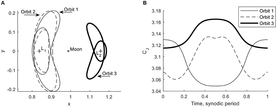
Figure 2. Selected solar-sail Lyapunov orbits. (A) Orbits. (B) Jacobi constant value along the orbits.
The stability analysis carried out in Heiligers et al. [15] showed that all three orbits in Figure 2A are highly unstable, implying the existence of stable and unstable invariant manifolds [9, 43]. Trajectories along these manifolds can be obtained by propagating the dynamics in Equation (1) from a state-vector along the stable and unstable eigenvectors of the linearized system around the periodic orbit, i.e., the reference trajectory, r0. Replacing r → r0 + δr in Equation (1) gives the following linearized system
and
Note that the solar-sail induced acceleration does not appear in the linearized system as it is not a function of the Cartesian position coordinates. This is a direct result of the assumption that ||rs→S|| = rS and therefore that the solar radiation pressure is constant throughout the Earth-Moon system. For a system of the form , the state-vector at time t after the initial time t0 can be obtained through the state transition matrix (STM), Φ(t; t0), as
where the STM can be obtained by simultaneously propagating the equations of motion in Equation (1) and
The STM evaluated after one full orbit, i.e., at time t = t0 + PS, is called the monodromy matrix. Its six eigenvalues, λi with i = 1, 2, …, 6, appear in reciprocal pairs and define the linear stability properties of the orbit. An orbit is stable if all six eigenvalues lie on the unit circle. If the norm of any of the eigenvalues is larger than one, ||λi|| > 1, the orbit is unstable, with larger norm values indicating greater instability. The largest eigenvalues, λmax = max(λi), for orbits 1–3 in Figure 2A are 7.09410 × 10⁵, 11.08556 × 10⁵, and 8.12799 × 10⁵, respectively, indicating that these orbits are indeed highly unstable. The unstable invariant manifold is defined as the set of trajectories that the spacecraft takes if it is perturbed anywhere along the orbit in the direction of the local eigenvector associated with this largest eigenvalue, [9, 43]. Similarly, the stable invariant manifold contains all trajectories that a spacecraft takes backwards in time after a perturbation in the direction of the local eigenvector associated with the eigenvalue [9, 43]. This manifold contains the trajectories that asymptotically wind onto the periodic orbit. The local stable and unstable eigenvectors along the orbit at any time t, wU(t) and wS(t), can efficiently be obtained after a single, full-orbit propagation of the STM through
Initial conditions along the local unstable and stable invariant manifolds, and , are obtained by perturbing any state vector along the periodic orbit, , by a magnitude ε along the unstable and stable eigenvectors as
The actual trajectories along the unstable invariant manifolds can be obtained by forward propagating the initial condition in Equation (12) in the dynamics of Equation (1), whereas the actual trajectories along the stable invariant manifolds can be obtained by backward propagating the initial conditions in Equation (13) in the dynamics of Equation (1). Note that the dynamics in Equation (1) include the solar-sail induced acceleration. The propagation thus leads to solar-sail assisted manifold trajectories where the same sail steering law is applied as in the orbits themselves, i.e., . This steering law will be used throughout the paper unless explicitly mentioned otherwise (from the section “Non-zero Pitch Angles” onwards). The plus-minus signs in Equations (12) and (13) represent the two branches of the invariant manifolds that either move toward the smaller body (the interior manifold) or away from the smaller body (the exterior manifold). In this work, only the interior manifolds will be exploited for both the homoclinic and heteroclinic connections. Finally, in this work a value for the perturbation magnitude in Equations (12) and (13) of ε = 10−6 (0.38 km) is used.
The resulting solar-sail assisted manifolds for orbit 1 appear in Figure 3. This figure has been generated by propagating 50 trajectories along each manifold (unstable/stable and interior/exterior) for an integration time of 1.2 PS and by truncating the trajectories when their distance to the Moon becomes smaller than twice the lunar radius to prevent operational difficulties. The red trajectories follow the unstable manifold, whereas the green trajectories follow the stable manifold. The figure shows that the symmetry, which is inherent in the classical CR3BP, is preserved in the solar-sail CR3BP due to the periodicity and symmetry of the solar-sail induced acceleration. Therefore, the interior and exterior unstable and stable manifolds are mirrored in the (x, z) plane. More specifically, mirrored trajectories can be found for initial conditions and along the solar-sail Lyapunov orbits.
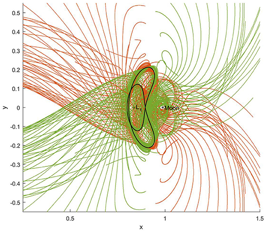
Figure 3. Trajectories along the solar-sail assisted stable (green) and unstable (red) manifolds of orbit 1.
For the rest of the paper, it is useful to specify a set of conventions, see Figure 4. This will allow to properly define the initial and final conditions of the unstable and stable manifold trajectories as well as the time of linkage between these trajectories. The initial conditions of the (un)stable manifold trajectories are defined as discretized coordinates along the periodic orbits, while their final conditions and the time of linkage are defined through the integration time along the manifolds. Note that, throughout this and the following sections, a subscript M relates to variables associated with the manifold trajectories, while the omission of the subscript M refers to variables associated with the solar-sail periodic orbits.
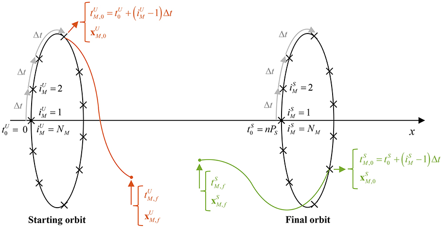
Figure 4. Schematic of conventions. Note that, for a homoclinic connection the starting and final orbits are the same orbit.
First of all, the initial time in the starting and final solar-sail Lyapunov orbits are designated by and , respectively, see Figure 4. The initial time in the final orbit, , occurs an integer number of synodic periods after , i.e., to allow time for the homo- or heteroclinic transfers to take place. Note that can be seen as the earliest arrival time in the final orbit. The value chosen for n will determine how much time is allowed for the transfer and may take on different values for different cases throughout the paper to achieve the best results.
The orbits are discretized into NM number of equally spaced points in time from where different manifold trajectories are assumed to start. The actual node numbers are denoted by and for the unstable and stable manifold trajectories, respectively, with and from 1 to NM, see again Figure 4. Note that the first and last nodes coincide, i.e., and as well as and , in order to demonstrate some periodic features throughout the paper. The time between discretization nodes is given by Δt = PS/(NM − 1). The time at each of the discretization nodes is the initial time of the manifold trajectory and is given by for the starting orbit and for the final orbit. The state vector at the start of the unstable and stable manifold trajectories are denoted as and . These are propagated over an integration time of and up to the final times and so that and . The state vectors at the end of the propagation are denoted as
For a connection, the state vectors at the end of the unstable and stable manifold trajectories should match, i.e., , which occurs at the linking time, tlink. This implies that the following four constraints need to be satisfied
For the classical (no-solar sail) case, two of these constraints can easily be satisfied by choosing a suitable Poincaré section, e.g., by propagating both the unstable and stable manifold trajectories up to , thereby inherently satisfying the first constraint in Equation (14). In addition, by choosing the starting and final orbits such that they have the same Jacobi constant value (which is inherently the case for a classical homoclinic connection), the compliance of another constraint, e.g., the third constraint in Equation (14), can be ensured. This leaves only the compliance of two constraints to be evaluated, which can be found visually by plotting the values for and at the Poincaré section.
When adding the time-dependent solar-sail induced acceleration to the dynamics, an additional constraint needs to be satisfied: the ends of the stable and unstable trajectories not only need to match in the spatial domain, but also in time
The consequence of this time constraint is that it impedes the use of “spatial” Poincaré sections as the time of arrival at the Poincaré section will be different for each trajectory. Instead, Poincaré sections “in time” will have to be used, where all trajectories are not propagated up to, for example, a prescribed x coordinate, but up to a specific integration time.
The time-dependent solar-sail induced acceleration also impedes the use of the Jacobi constant to automatically satisfy one of the constraints in Equation (14). The Jacobi constant is defined as [41]
First of all, for heteroclinic connections between solar-sail periodic orbits in the Earth-Moon system (like the solar-sail Lyapunov orbits considered in this paper), it will be difficult, if not impossible, to find two orbits with the same value for CJ, as the main orbit selection criterion will be that both orbits exist for the same sail technology, i.e., for the same value for a0, EM. Furthermore, due to the time dependent solar-sail induced acceleration, the value for CJ is not constant along the orbits, see Figure 2B. Though not constant, its value is periodic and could therefore potentially provide a means to reduce the number of constraints. However, as soon as the manifold trajectories are being propagated from their initial condition, the periodicity in the value for CJ is lost, see Figure 5.
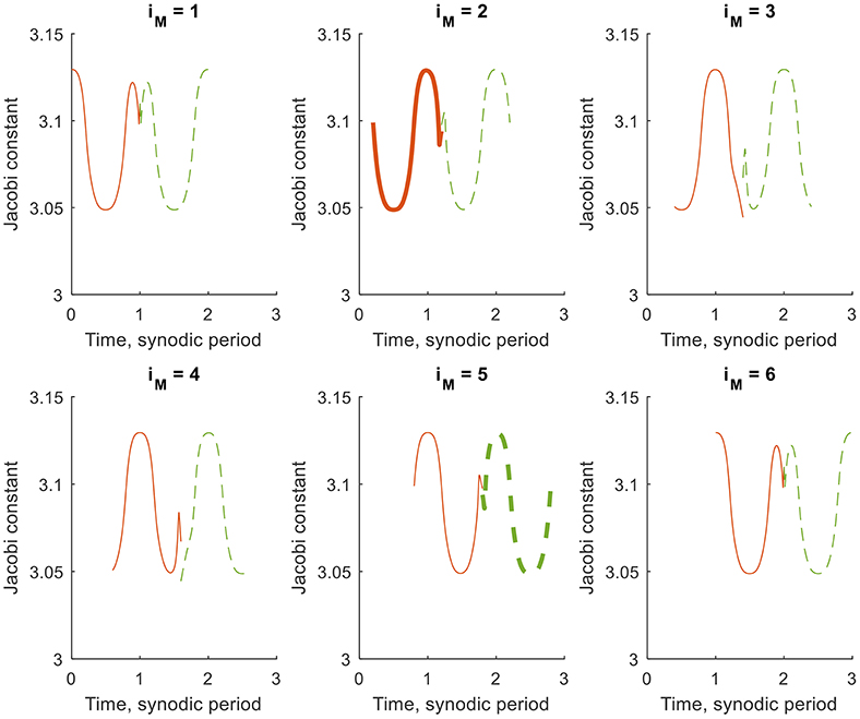
Figure 5. Jacobi constant along six trajectories along the stable (red, solid) and unstable (green, dashed) manifolds of orbit 1, where .
Figure 5 provides the CJ-value along the stable and unstable manifolds of orbit 1 for NM = 6 (six trajectories per manifold), n = 2 (the earliest arrival time in the final orbit is two synodic periods after the initial time of the starting orbit), and (the manifold trajectories are propagated for one synodic period). By selecting the parameter values as such, the time constraint in Equation (15) is automatically satisfied for . However, the different plots in Figure 5 show a difference in CJ-value at the end of the stable and unstable manifold trajectories for . Only for does the symmetry in the dynamical system guarantee the same CJ-value after an integer number of synodic periods, see for example the thick lines for 2 and 5 in Figure 5. However, for this combination of manifold trajectories, the time constraint is not satisfied, i.e., while a link in CJ-value exists, the trajectories do not link in time. It can therefore be concluded that the Jacobi constant does not provide any benefit in the search for either homoclinic or heteroclinic connections between solar-sail Lyapunov orbits in the Earth-Moon system.
The previous section has demonstrated that methods, conventionally used to find homo- or heteroclinic connections between Lyapunov orbits in the classical Earth-Moon system, do not apply for the inclusion of a solar-sail induced acceleration. Connections can therefore not simply be obtained from a visual inspection of two-dimensional spatial Poincaré sections. This section will explore a different methodology, where the time constraint in Equation (15) is satisfied by suitable choices of “temporal” Poincaré sections (either by defining a fixed propagation time, see the section “Fixed Propagation Time”, or a fixed linkage time, see the section “Fixed Linkage Time”). Furthermore, the coordinate constraints in Equation (14) are assessed by defining the following figure of merit (or objective):
with w a weight and
The objective in Equation (17) is thus a weighted sum of the error in dimensionless position and dimensionless velocity between the ends of the unstable and stable manifold trajectories. In this work, a value for the weight of w = 5 is selected. This value is based on trial runs as well as the fact that an error in velocity is of slightly less importance than an error in position as it can be physically overcome, e.g., in worst case, by an additional propulsion source.
For brevity, the applicability of the proposed tools will be explored for homoclinic connections only, i.e., for transfers 1–3, and will be shown to provide a good framework. However, more flexibility in both the temporal “positioning” of the Poincaré section as well as other design parameters such as the solar-sail steering law is required to fully satisfy the constraints in Equations (14) and (15). This will be further explored for the homo- and heteroclinic connections separately in the sections “Homoclinic Connections” and “Heteroclinic Connections”, respectively.
In the section “Problem Definition”, a propagation time of one synodic period was used to generate the results in Figure 5, in which case the time constraint in Equation (15) is satisfied only for connections between trajectories where . This can be generalized to a propagation time of any integer number of synodic periods, i.e., . Then, the total transfer time becomes 2nint and thus n = 2nint, i.e., and .
The results for nint = 1 and NM = 1,000 appear in Figure 6 and in the first data column of Table 2 (heading “Fixed propagation time”). Note that the other columns in Table 2 will be discussed in the following sections where more advanced approaches in the search for homoclinic connections will be explored. The figures in the top row of Figure 6 provide for transfers 1–3 the objective value for the different manifold trajectory numbers, i.e., for different values for . Gaps in these results appear due to the early truncation of trajectories that approach the Moon at less than twice the lunar radius. The figures clearly show the symmetry in the dynamics, i.e., the results in terms of objective value are the same for and . The computational effort for generating these results could thus be reduced by only considering . The red star indicates one of two minima in the objective value with further numerical values on the departure, link and arrival times (, tlink, and , all in synodic period units) in Table 2. These different epochs are all one synodic period apart due to the fixed propagation time. The figures in the bottom row of Figure 6 show the actual unstable (red) and stable (green) manifold trajectories corresponding to that minimum objective value, where circles and crosses mark the start and end of the manifold trajectories. Due to the condition , the circles overlap. For true homoclinic connections, the crosses should also overlap. This is clearly not the case for the results in Figure 6. In fact, Table 2 shows that the errors on the position are between 18,000 and 83,000 km and that the errors on the velocity are in the range 17–606 m/s. Note that longer integration times have been considered, e.g., nint = 2, but that this did not lead to improvements in the objective value.
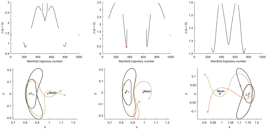
Figure 6. Search for homoclinic connections for a fixed propagation time of one synodic period (FLTR: transfers 1–3).
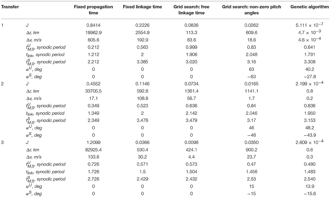
Table 2. Objective value, dimensional errors on position and velocity, and further details for transfers 1–3 for different approaches in the search for homoclinic connections.
To loosen the requirement that only connections for can be explored, this section moves away from a fixed propagation time of an integer number of synodic periods and instead propagates the initial conditions and forward and backward up to a specific linkage time, tlink. Consequently, and Equation (15) is automatically satisfied. The results can then be presented as temporal Poincaré sections at the linkage time, see the figures on the left-hand side of Figure 7. In this figure, the red and green dots represent the position coordinates at the end of the unstable and stable manifold trajectories, respectively, for transfers 1–3. For transfers 1 and 2, these Poincaré sections are generated for n = 3 (i.e., and ), while for transfer 3 better results were obtained for n = 2 (i.e., and ). Furthermore, the linkage time is defined halfway, i.e., , NM = 1,000 and trajectories that approach the Moon by less than twice the lunar radius are again discarded.
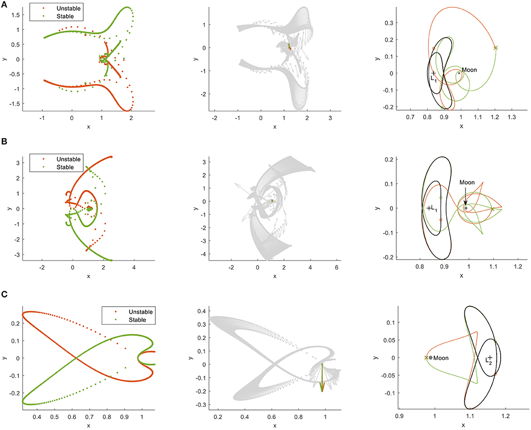
Figure 7. Search for homoclinic connections for a fixed linkage time. (A) Transfer 1. (B) Transfer 2. (C) Transfer 3.
The symmetry in the dynamics is once again clear from these figures (allowing the computational effort to be halved) and some connections in position can be observed, i.e., where the red and green dots overlap. Information on the velocity at the end of each trajectory can be included in the temporal Poincaré sections by using the “glyph representation” introduced by Haapala and Howell [38]. This glyph representation is shown in the figures in the middle column of Figure 7 where an arrow indicates a scaled version of the velocity vector at the end of the unstable and stable manifold trajectories, i.e., and . If a green and red dot overlap and the accompanying velocity arrows are of the same magnitude and point in the same direction, a homoclinic connection is established. The best connection, i.e., the combination of unstable and stable manifold trajectories with the smallest objective value in Equation (17), is highlighted in color in the figures in the middle column of Figure 7, while all other velocity vectors are marked in gray. The corresponding trajectories appear on the right-hand side of Figure 7. Comparing these trajectories with those in Figure 6 shows the improvement that a fixed linkage time can establish over a fixed propagation time. Actual numerical values on the objective value and errors in position and velocity are provided in the second data column of Table 2 (heading “Fixed linkage time”), which shows a reduction in the objective by a factor 3.7–33.1 and a reduction in the position error of 1–2 orders of magnitude.
This section has shown the usability of temporal Poincaré sections and the figure of merit in Equation (17) for the search of homoclinic connections. However, the highly constrained definition of the temporal Poincaré section as well as other design parameters such as the solar-sail steering law, cause the absolute values for the linkage errors to be too large in order to consider these transfers as true homoclinic connections. The subsequent sections will therefore introduce more flexibility into the design of the homo- and heteroclinic connections in the sections “Homoclinic Connections” and “Heteroclinic Connections”, respectively.
Building on the results found for homoclinic connections in the previous section, this section introduces more flexibility into the design of the homoclinic connections by allowing the linkage time to be freely selected and by adopting non-zero solar-sail pitch laws. To find the optimal linkage time and sail-steering law, two approaches are adopted: a simple grid search in the section “Grid Search” and a genetic algorithm approach in the section “Genetic Algorithm”.
This section will explore the use of grid searches to improve the quality of the homoclinic connections by choosing a free linkage time, see the section “Free Linkage Time”, and non-zero solar-sail pitch angles, see the section “Non-zero Pitch Angles”.
To explore the idea of a free linkage time, the following grid-search approach is adopted:
- NM = 1,000 trajectories are propagated along the unstable and stable manifolds for two synodic periods, i.e., .
- As in the previous section, n = 3 for transfers 1 and 2, while n = 2 for transfer 3. This means that the initial conditions of the trajectories along the unstable and stable manifolds are bound to the domains and and (n = 3).
- A minimum transfer time of 0.9PS is enforced to ensure that the trajectories will sufficiently move away from the solar-sail Lyapunov orbits. The final conditions of the trajectories along the unstable and stable manifolds are then confined to the domains and (n = 2) and (n = 3). There thus exists an overlap in linkage time in the domain (n = 2) and (n = 3).
- Each propagated trajectory is interpolated at nnodes = 1,000 equally spaced nodes in time.
- The position and velocity coordinates at those nodes are stored in four individual matrices (one for each of the two position and two velocity coordinates) of size . The rows of these matrices represent the trajectory numbers, whereas the columns represent the time at the nodes. This is further demonstrated in Figure 8 for transfer 1, where the horizontal and vertical axes can be interpreted as the columns and rows of the matrices, respectively, and the colored surfaces indicate which elements of the matrices are filled. Note that the gaps in Figure 8 are introduced by an early truncation of the trajectories because of a close lunar approach.
- After filling up the four individual matrices, for each potential linkage time [i.e., for each column between (n = 2) or (n = 3)], the errors in position and velocity for each combination of rows of the matrices for the stable and unstable manifolds are computed.
- Finally, the absolute minimum objective value for the best linkage time is extracted and the corresponding unstable and stable manifold trajectories are further evaluated.
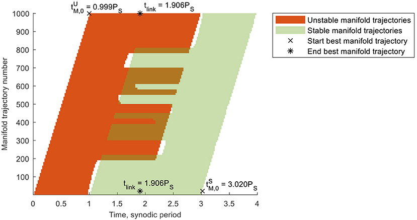
Figure 8. Trajectory times per manifold trajectory number for transfer 1 including the departure, link, and arrival epochs for the best stable and unstable manifold trajectories.
The results for transfers 1–3 appear in Figure 9. The figures in the top row of Figure 9 show the smallest objective value at each possible linkage time and the red star indicates the absolute minimum. The corresponding trajectories appear in the bottom row of Figure 9 with numerical values for the objective, errors in position and velocity, and departure, link and arrival epochs in the third data column of Table 2 (heading “Grid search: free linkage time”). For transfer 1, the epochs are also illustrated in Figure 8. From Table 2 it can be concluded that a free linkage time further reduces the objective value by a factor 2.7–8.9, bringing the errors on the position and velocity at linkage down to less than the lunar radius (< 1,738 km) and < 100 m/s, respectively. For transfer 3, the result is very close to that for a fixed linkage time: the departure and arrival conditions along the solar-sail Lyapunov orbit and linkage time are only slightly changed. The result is a near-homoclinic connection with Δr = 424.1 km and Δv = 4.4 m/s.
Up to this point, the attitude of the solar sail in the stable and unstable manifold trajectories has been assumed equal to that of the solar-sail Lyapunov orbits, i.e., α = 0 and thus . This section investigates if further improvements on the objective value can be achieved by orienting the sail at a constant, but non-zero, pitch angle along the stable and unstable manifold trajectories. Note that, when considering non-zero pitch angles, the terms “invariant manifolds” or “manifold trajectories” no longer really apply, but that, for consistency, this paper will continue to use these terms.
By changing the sail's orientation with respect to the incoming solar radiation through the pitch angle, see Figure 1, the solar-sail induced acceleration changes as per Equation (4). Figure 10 demonstrates the effect of a non-zero pitch angle along the manifold trajectories of orbit 1. To generate Figure 10, the initial conditions at 1, i.e., and , are forward and backward propagated for different pitch angles in the unstable, αU, and stable, αS, manifold trajectories. In particular, a range in αU and αS of [−90o, 90o] is considered with a step size of 10o. Note that pitch angles larger than 70o may not always fall within mission constraints [29], but that the full theoretical range in pitch angles is considered in this paper for illustrative purposes. Also note that using different pitch angles in the stable and unstable manifold trajectories requires an instantaneous attitude change at linkage, but that this may be smoothed in future work by employing optimal control algorithms. However, this is considered beyond the scope of the current investigation.
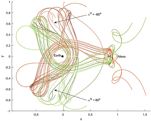
Figure 10. Effect of non-zero pitch angle on the unstable (red) and stable (green) manifold trajectories of orbit 1 for 1, i.e., at , and for pitch angles between −90· (dark color) and 90· (light color) with a step size of 10·.
Figure 10 shows that, by pitching the sail away from αU = αS = 0, a wealth of new trajectories arises. Note that the sign in Equations (12) and (13) is chosen such that the interior manifold results for αU = αS = 0 and that non-zero pitch angles subsequently cause the manifold trajectories to divert away from the Moon and move toward the Earth. The figure furthermore shows that the symmetry as explained in the section “Solar-sail Assisted Invariant Manifolds” is maintained for and as long as αU = −αS, see the trajectories indicated with αU = −60· and αS = 60· in Figure 10.
To assess the improvement in the objective value for non-zero pitch angles, the approach detailed in the section “Free linkage Time” is expanded by a loop around that approach to evaluate the minimum objective value for a mesh in αU of αU∈[−90·, 90·] with a step size of 1·. The pitch angle in the stable manifold trajectories is constrained to αS = −αU The only difference with respect to the approach in the section “Free linkage Time” is a reduction in the number of manifolds trajectories to NM = 100 to counter the increase in computational time introduced by the loop over αU. The trajectories that yield the smallest objective value for transfers 1–3 appear in the top row of Figure 11 with numerical values in the fourth data column of Table 2 (heading “Grid search: non-zero pitch angles”). From Table 2 it can be concluded that the best trajectories abide by, or are close to, the condition of and (i.e., the sum of and is equal to an integer number of synodic periods) and thus exploit the symmetry in the system. This is also clear from the position of the circle markers in Figure 11. As such, for transfers 1 and 2 a further reduction in the objective value of a factor 3.2–4.4 is achieved to position and velocity errors that start to resemble true homoclinic connections. However, the reduction in the number of manifold trajectories from NM = 1000 in the previous section to NM = 100 in the current investigation leads to an increase in the objective value for transfer 3.
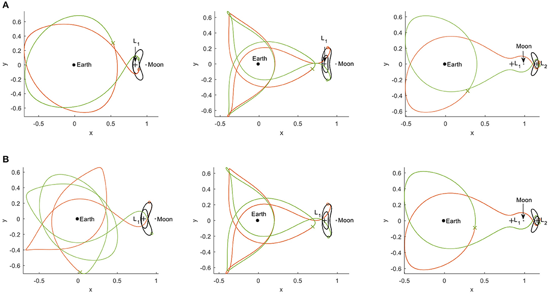
Figure 11. Best homoclinic connections (FLTR: transfers 1–3). (A) For opposite-sign pitch angles. (B) For genetic algorithm approach.
The use of a grid search inherently limits the search space to discrete steps in the departure/arrival locations along the solar-sail Lyapunov orbits ( and ), the linkage time, tlink, and the pitch angles in the unstable and stable manifold trajectories (αU and αS). To efficiently explore the design space in between these discrete steps, this section investigates the use of a genetic algorithm. In particular, the Matlab® function ga.m is used to find the values for the design parameters, pGA, that minimize the objective in Equation (17). The parameters are the previously used design variables , , αU, αS, and tlink, and bounds on these parameters are defined as
Furthermore, the following linear constraints are imposed to ensure that departure, linkage and arrival occur sequentially
In Equation (20), ξ represents the previously introduced minimum transfer time to ensure that the trajectories move sufficiently away from the solar-sail Lyapunov orbits
The genetic algorithm is initiated for a population of 1,000 individuals, is run for 100 generations and for five different seeds of the random generator to account for the inherent randomness of the genetic algorithm approach. For ease of implementation, the ga.m function is used with its default settings. The results appear in the bottom row of Figure 11 and in the last column of Table 2. Especially the last column of Table 2 shows that the continuous, instead of discrete, design space for the design parameters enables a reduction in the objective value of several orders of magnitude, with resulting errors in the position and velocity of < 1 km and < 1 m/s. This proves the feasibility of homoclinic connections between solar-sail Lyapunov orbits as well as the applicability of temporal Poincaré sections, the figure of merit in Equation (17), and the genetic algorithm approach for finding these connections.
This section follows the same approach as in the section “Homoclinic Connections” to find heteroclinic connections between the different solar-sail Lyapunov orbits, see trajectories 4–6 in Table 1. However, while that section first considered zero-pitch angles in the stable and unstable manifold trajectories, followed by opposite-sign pitch angles, the section “Grid Search” below will immediately merge those approaches based on the improvements that non-zero pitch angles provided. The section “Grid Search” will even expand the search space on the usable pitch angles. Subsequently, in the section “Genetic Algorithm” the genetic algorithm approach will be applied to the search for heteroclinic connections.
To consider a wide range of pitch angle values in both the stable and unstable manifold trajectories, this section takes an approach similar to the one described in the section “Non-zero Pitch Angles”. However, that section constrained the pitch angle in the stable manifold trajectory to αS = −αU to exploit the symmetry in the system. Because this symmetry is lost for heteroclinic connections, this section allows αS to take on any value within a predefined mesh. For this, an extra loop is created around the approach in the section “Non-zero Pitch Angles”, where now the inner- and outer loops consider meshes in the pitch angles of αU∈[−90·, 90·] and αS∈[−90·, 90·]. Note that the only differences with the methodology for the grid search for homoclinic connections are that no minimum transfer time is defined, that n = 3 for all transfers, and that, to limit the increase in computation cost introduced by the additional loop, the step size in αU and αS is increased to 10·.
For each combination of αU and αS, the unstable and stable manifold trajectories that yield the smallest objective value for transfers 4–6 appear in the top row of Figure 12. From this figure the lack in symmetry for the heteroclinic connections is indeed clear. The best result, i.e., the combinations of αU and αS that lead to the absolute minimum objective value are indicated by a white cross. Further details on these trajectories are shown in the middle row of Figure 12 with numerical details in the first data column of Table 3 (heading “Grid search: non-zero pitch angles”). The remaining results in these tables will be discussed in the section “Genetic Algorithm” below. Despite the lack in symmetry, the objective values in Table 3 hint at the possibility for heteroclinic connections with errors on the position and velocity that are of similar magnitude as for the “opposite-sign pitch angles”-approach in the section “Non-zero Pitch Angles”. Finally, from the data in Table 3 it is interesting to note that very large pitch angles provide the best results. Since very large pitch angles create very small solar-sail induced accelerations, the current approach appears to provide the best heteroclinic connections by exploiting the (near-)classical dynamics.
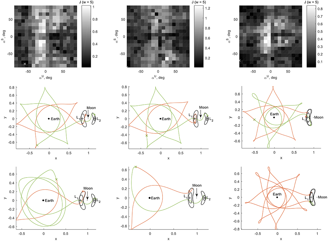
Figure 12. Best heteroclinic connections (FLTR: transfers 4–6) for grid search in pitch angles (top and middle row) and for genetic algorithm approach (bottom row).
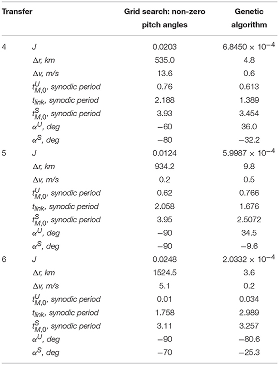
Table 3. Objective value, dimensional errors on position and velocity, and further details for transfers 4–6 for different approaches in the search for heteroclinic connections.
The second, and final, step in the search for heteroclinic connections is near-identical to the approach previously described for homomclinic connections: a genetic algorithm is taken at hand to explore the design space in between the discrete steps of the meshes used in the previous section for the design parameters , , tlink, αU, and αS. The set-up of the algorithm is that as described in the search for homoclinic connections, only the margin on the minimum transfer time in the unstable and stable manifold trajectories is significantly loosened, i.e., ξ = 0.01PS for use in Equation (20).
The results appear in the bottom row of Figure 12 with numerical details in the last column of Table 3. With errors in the position and velocity of < 10 km and < 1 m/s, also the feasibility of heteroclinic connections between solar-sail Lyapunov orbits and the suitability of the proposed tools has been demonstrated. While for the grid searches in the previous section the best pitch angles were of rather large values, the genetic algorithm approach shows that much smaller angles (and therefore significant solar-sail induced accelerations) are required to establish these connections.
This paper has established an understanding of, and a framework for, the computation of homo- and heteroclinic connections between planar solar-sail Lyapunov orbits in the Earth-Moon three-body problem. These connections have been found by linking the unstable and stable solar-sail assisted invariant manifolds associated to the orbits. Since the solar-sail induced acceleration introduces a time dependency into the dynamics, the use of traditional techniques (Jacobi constant and spatial Poincaré sections) were proven to be of no benefit in the search for these connections. Instead, connections have been found by introducing temporal Poincaré sections, defining a suitable figure of merit to assess the quality of the connections, and using grid searches on the departure, arrival and linkage times as well as on constant, non-zero solar-sail pitch angles in the unstable and stable manifold trajectories. While these methods allowed to find homo- and heteroclinic connections with errors on the position and velocity at linkage of < 1,525 km and < 25 m/s, true connections were only found when exploring the design space in between the discrete mesh of the grid search. For this a genetic algorithm approach has been successfully applied, reducing the errors down to < 10 km and < 1 m/s. With that, this paper has proven the feasibility of homo- and heteroclinic connections between solar-sail Lyapunov orbits for a simple solar-sail steering strategy in the form of a piece-wise constant sail attitude. These results and the framework defined in this paper form only the start of a much larger investigation into homo- and heteroclinic connections between other planar solar-sail periodic orbits in the Earth-Moon system as well as into the extension to the spatial, three-dimensional case.
JH: idea conception, problem formulation, method development, method implementation, data generation, data analysis, result interpretation, and manuscript writing.
The author declares that the research was conducted in the absence of any commercial or financial relationships that could be construed as a potential conflict of interest.
1. Ross S, Lo M. The lunar L1 gateway - portal to the stars and beyond. In: AIAA Space 2001 Conference and Exposition, American Institute of Aeronautics and Astronautics (2001).
2. Parker JS. Establishing a Network of Lunar Landers via Low-Energy Transfers (AAS 14-472). Sante Fe, NM: AAS/AIAA Space Flight Mechanics Meeting (2014).
3. Farquhar R. Lunar communications with libration-point satellites. J Spacecraft Rockets (1967) 4:1383–4. doi: 10.2514/3.29095
4. Heiligers J, Parker JS, Macdonald M. Novel solar-sail mission concept for high-latitude earth and lunar observation. J Guidance Control Dyn. (2018) 41:G002919. doi: 10.2514/1.G002919
5. Olson J, Craig D, Maliga K, Mullins C, Hay J, Graham R, et al. Voyages: Charting the Course for Sustainable Human Exploration. Hampton, VA: NASA Langley Reesearch Center (2011).
6. Vergaaij M, Heiligers J. Time-optimal solar sail heteroclinic connections for an earth-mars cycler. 68th International Astronautical Congress. Adelaide (2017).
7. Szebehely V. Theory of Orbits: The Restricted Problem of Three Bodies. New York, NY: Elsevier (1967).
8. Howell KC. Families of orbits in the vicinity of the collinear libration points. J Astronaut Sci. (2001) 49:107–25. doi: 10.2514/6.1998-4465
9. Koon WS, Lo MW, Marsden JE, Ross SD. Dynamical Systems, the Three-Body Problem and Space Mission Design. New York, NY: Springer (2006).
10. Howell KC, Pernicka HJ. Numerical determination of lissajous trajectories in the restricted three-body problem. Celes Mech. (1988) 41:107–24.
11. Hénon M. Numerical exploration of the restricted problem. V. Hill's case periodic orbits and their stability. Astron Astrophys. (1969) 1:223–38.
12. Howell KC. Three-dimensional, periodic, 'Halo' orbits. Celes Mech Dynamic Astron. (1983) 32:53–71.
13. Kazantzis PG. Numerical determination of families of three-dimensional double-symmetric periodic orbits in the restricted three-body problem. I. Astrophys Space Sci. (1979) 65:493–513.
14. Kazantzis PG. Numerical determination of families of three-dimensional double-symmetric periodic orbits in the restricted three-body problem. II. Astrophys Space Sci. (1980) 69:353–68.
15. Heiligers J, Macdonald M, Parker JS. Extension of earth-moon libration point orbits with solar sail propulsion. Astrophys Space Sci. (2016) 361:241. doi: 10.1007/s10509-016-2783-3
16. McInnes CR. Solar Sailing: Technology, Dynamics and Mission Applications. Berlin: Springer-Verlag (1999). doi: 10.1007/978-1-4471-3992-8
17. Macdonald M, McInnes C. Solar sail science mission applications and advancement. Adv Space Res. (2011) 48:1702–16. doi: 10.1016/j.asr.2011.03.018
18. Heiligers J, Diedrich B, Derbes B, McInnes CR. Sunjammer: preliminary end-to-end mission design. In: 2014 AIAA/AAS Astrodynamics Specialist Conference. San Diego, CA (2014).
19. McInnes C, Bothmer V, Dachwald B, Geppert UME, Heiligers J, Spietz A, et al. Gossamer roadmap technology reference study for a sub-L1 space weather mission. In: Macdonald M, editor. Advances in Solar Sailing. Berlin: Springer (2014). p. 227–42.
20. Dachwald B, Boehnhardt H, Broj U, Geppert URME, Grundmann J-T, Reinhard W, et al. Gossamer roadmap technology reference study for a multiple NEO rendezvous mission. In: Macdonald M, editor. Advances in Solar Sailing. Berlin: Springer (2014) 211–226.
21. Peloni A, Ceriotti M, Dachwald B. Solar-sail trajectory design for a multiple near-earth-asteroid rendezvous mission. J Guidance Control Dyn. (2016) 39:2712–24. doi: 10.2514/1.G000470
22. Macdonald M, Hughes C, McInnes L, Falkner AP, Atzei A. GeoSail: an elegant solar sail demonstration mission. J Spacecraft Rockets (2007) 44:784–96. doi: 10.2514/1.22867
23. Waters TJ, McInnes CR. Periodic orbits above the ecliptic in the solar-sail restricted three-body problem. J Guidance Control Dyn. (2007) 30:687–93. doi: 10.2514/1.26232
24. Walmsley M, Heiligers J, Ceriotti M, McInnes C. Optimal trajectories for planetary pole-sitter missions. J Guidance Control Dyn. (2016) 39:2461–8. doi: 10.2514/1.G000465
25. JAXA. Press Releases: Small Solar Power Sail Demonstrator ‘IKAROS' Confirmation of Photon Acceleration (2010). Available online at: http://www.jaxa.jp/press/2010/07/20100709_ikaros_e.html (Accessed 9 July 2010).
26. Johnson L, Whorton M, Heaton A, Pinson R, Laue G, Adams C. NanoSail-D: a solar sail demonstration mission. Acta Astronaut. (2011) 68:571–5. doi: 10.1016/j.actaastro.2010.02.008
27. Biddy C, Svitek T. LightSail-1 solar sail design and qualification. In: Proceedings of the 41st Aerospace Mechanisms Symposium. Pasadena, CA: Jet Propulsion Laboratory (2012). p. 451–63.
28. McNutt L, Johnson L, Clardy D, Castillo-Rogez J, Frick A, Jones L. Near-earth asteroid scout. In: AIAA SPACE 2014 Conference and Exposition. San Diego, CA: American Institute of Aeronautics and Astronautics (2014).
29. Heaton A, Ahmad N, Miller K. Near earth asteroid scout solar sail thrust and torque model (17055). In: 4th International Symposium on Solar Sailing. Kyoto: Japan Space Forum (2017).
30. Jorba-Cuscó M, Farrés A, Jorba À. Periodic and quasi-periodic motion for a solar sail in the earth-moon system. In: 67th International Astronautical Congress. Guadalajara (2016).
32. Broschart SB, Chung MJ, Hatch SJ, Ma JH, Sweetser TH, Angelopoulos SS, et al. Preliminary trajectory design for the ARTEMIS Lunar Mission (AAS 09-382). In: Space Flight Mechanics Meeting. Savannah, GA (2009).
33. Gómez G, Masdemont JJ. Some zero cost transfers between libration point orbits. Adv Astronaut Sci. (2000) 105:1199–215.
34. Koon WS, Marsden JE, Ross SD. Heteroclinic connections between periodic orbits and resonance transitions in celestial mechanics. Chaos (2000) 10:427–69. doi: 10.1063/1.166509
35. Gómez G, Koon WS, Lo MW, Marsden JE, Masdemont J, Ross SD. Connecting orbits and invariant manifolds in the spatial restricted three-body problem. Nonlinearity (2004) 17:1571–606. doi: 10.1088/0951-7715/17/5/002
36. Canalias E, Josep JM. Homoclinic and heteroclinic transfer trajectories between planar Lyapunov orbits in the sun-earth and earth-moon systems. Discrete Continuous Dyn Syst A (2005) 14:261–79. doi: 10.3934/dcds.2006.14.261
37. Barrabés E, Mondelo JM, Ollé M. Numerical continuation of families of homoclinic connections of periodic orbits in the RTBP. Nonlinearity (2009) 22:2901. doi: 10.1088/0951-7715/22/12/006
38. Haapala AF, Howell KC. A framework for constructing transfers linking periodic libration point orbits in the spatial circular restricted three-body problem. Int J Bifurcation Chaos (2016) 26:1630013-1630011. doi: 10.1142/S0218127416300135
39. Stuart J, Ozimek M, Howell K. Optimal, low-thrust, path-constrained transfers between libration point orbits using invariant manifolds. In: AIAA/AAS Astrodynamics Specialist Conference. Toronto, ON: American Institute of Aeronautics and Astronautics (2010).
40. Heiligers J, Mingotti G, McInnes CR. Optimal solar sail transfers between halo orbits of different sun-planet systems. Adv Space Res. (2015) 55:1405–21. doi: 10.1016/j.asr.2014.11.033
41. Battin RH. An Introduction to the Mathematics and Methods of Astrodynamics, Rev ed. Reston, VA: American Institute of Aeronautics and Astronautics, Inc. (1999). doi: 10.2514/4.861543
42. McInnes CR. Solar sail trajectories at the lunar L2 lagrange point. J Spacecraft Rockets (1993) 30:782–4. doi: 10.2514/3.26393
Keywords: solar sailing, circular restricted three-body problem, homoclinic connections, heteroclinic connections, transfer trajectories, Lyapunov orbits, libration point orbits
Citation: Heiligers J (2018) Homo- and Heteroclinic Connections in the Planar Solar-Sail Earth-Moon Three-Body Problem. Front. Appl. Math. Stat. 4:42. doi: 10.3389/fams.2018.00042
Received: 07 May 2018; Accepted: 22 August 2018;
Published: 10 October 2018.
Edited by:
Elisa Maria Alessi, Consiglio Nazionale Delle Ricerche (CNR), ItalyReviewed by:
Esther Barrabes, University of Girona, SpainCopyright © 2018 Heiligers. This is an open-access article distributed under the terms of the Creative Commons Attribution License (CC BY). The use, distribution or reproduction in other forums is permitted, provided the original author(s) and the copyright owner(s) are credited and that the original publication in this journal is cited, in accordance with accepted academic practice. No use, distribution or reproduction is permitted which does not comply with these terms.
*Correspondence: Jeannette Heiligers, bS5qLmhlaWxpZ2Vyc0B0dWRlbGZ0Lm5s
Disclaimer: All claims expressed in this article are solely those of the authors and do not necessarily represent those of their affiliated organizations, or those of the publisher, the editors and the reviewers. Any product that may be evaluated in this article or claim that may be made by its manufacturer is not guaranteed or endorsed by the publisher.
Research integrity at Frontiers

Learn more about the work of our research integrity team to safeguard the quality of each article we publish.