 Francesco Positano
 Leonardo Lizzi
 Robert Staraj
- Laboratoire d'Electronique, Antennes et Télécommunications, Campus SophiaTech, Université côte d’Azur, Sophia Antipolis, France
The Internet of things is increasingly focused on UAV-based long-range applications. This necessitates versatile, low-cost antenna designs for both ground stations and drones. This study proposes the design of a pattern reconfigurable parasitic element antenna system operating in the LoRa 868 MHz band and its on-field characterization. The electronic steerable parasitic array radiator (ESPAR) antenna consists of a single-fed shorted patch surrounded by four rectangular parasitic elements. The antenna system can develop four directive beams, each activated by one of four PIN diodes, and an omnidirectional pattern obtained when all diodes are turned off. The antenna has been characterized both in an anechoic controlled environment and in a practical on-field drone-to-ground packet transmission scenario. Results based on received signal strength indicator (RSSI) show that the pattern reconfigurability becomes increasingly relevant with the end-point distance and that pointing the beam at the end point always allows the highest RSSI level to be received.
1 Introduction
The internet of things (IoT) is a large-scale network of interconnected devices that exchange data with each other and with the cloud (Heslop, 2021). IoT devices can range from simple sensors and actuators to complex systems, such as autonomous cars. Recently, there has been a growing evolution in infrastructures driven by unmanned aerial vehicles (UAVs), piquing the interest of Industrial IoT (IIoT) participants in the drone market (Cohn et al., 2017). Nonetheless, several challenges remain associated with the deployment of UAVs (Hayat et al., 2016; Hossein Motlagh et al., 2016), with long-range coverage and power consumption being critical aspects.
In this context, pattern reconfigurable antennas can play a significant role in overcoming many challenges, enhancing channel performance, and mitigating radiation losses in unintended directions (Catarinucci et al., 2014; Le et al., 2016). Instead of a classical approach of arranging position and orientation of conventional omnidirectional antennas (Badi et al., 2020), pattern reconfigurable antennas are increasingly used for drone applications (Seo et al., 2020; Kim et al., 2020) as they can dynamically adapt to the surrounding environment independent of the drone roll, pitch, or yaw in flight. Among the many existing pattern reconfigurable antenna solutions, electronically steerable parasitic array radiators (ESPARs), which use reactive loads to reconfigure the beam (Harrington, 1978), allow one to obtain a single-fed pattern reconfigurable antenna without the use of complex phase shifters and power dividers. In IoT scenarios, these arrays have performed comparably to active arrays (Burtowy et al., 2019; Santamaria et al., 2021a) with the benefit of low power consumption. ESPARs hold a distinct advantage by combining coplanar omnidirectional dipole-like radiating elements in a way that enables an end-fire propagation, which can be reconfigured to obtain an extensive coverage throughout the entire azimuthal plane (Positano et al., 2023). However, these designs need complex control circuits that involve many reactive loads for each parasitic element. Santamaria et al. (2021b) proposed an alternative where a cloverleaf-like antenna structure realizes a four-direction ESPAR with self-matched parasites to avoid the use of discrete load components. However, the use of a single pole n-throw (SPNT) switch configuration controller is needed.
In drone-to-ground (D2G) communications, it is preferable for antennas on UAVs to have conical beams pointed to the ground so that they can provide the widest possible coverage. In Choi et al. (2020), the conical beam is obtained thanks to the combination four directive beams. The structure is based on the combination of a monopole and patch structures while the reconfiguration is based on their feeding network control. A combination of monopole and orthogonal radial dipoles is proposed in Choi and Lee (2020), where the use of PIN diodes to control the coupling between the dipoles and the monopole allows the antenna to be simplified.
However, in real-world deployments, communication performance is constrained by various other factors such as the transmission protocol, the surrounding environment, and the integration with the supporting structure. Together with simulations and measurements in controlled environments, tests at higher levels in practical on-field deployment are needed to validate the efficiency of this communication (Pokorny et al., 2018).
This study introduces a four-direction ESPAR designed for operation in the LoRa 868 MHz band and an RSSI-based assessment in a real scenario to demonstrate the advantage and limits of using reconfigurable antennas for long range communications. Reconfigurability is achieved through the activation of four switchable beams through PIN diodes. The design is conceived for versatile D2G communication.
2 Design of the parasitic element antenna system
2.1 Antenna structure
The antenna structure is presented in Figure 1. It consists of a single-fed squared shorted patch surrounded by four rectangular patches. The central active radiating element represents the well-known wire-patch (WP) radiator (Delaveaud et al., 1994), which can develop an omnidirectional radiation pattern despite the small vertical extension. This is achieved by placing two shorting wires parallel to the SMA core connector at a distance
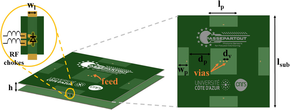
Figure 1. Antenna structure with zoom on parasite’s snap-fit PCB with PIN diode and RF chokes.
RF-chokes are needed at the ends of the PIN diodes on the vertical snap-fit PCBs to insulate the microcontroller used to activate the diodes from the RF signals. For this purpose, a 100 nH inductor providing a reactance of
The resulting system enables five pattern configurations: one omnidirectional configuration when all the diodes are OFF, and four directive patterns when the diodes are activated one by one. These latter patterns point in the directions opposite the corresponding activated parasitic element. The four directive beams can combine in a conical shape meeting the requirement for UAVs antennas.
2.2 Design procedure
The design process is described in the three following simple steps. Firstly, a simple squared WP antenna has been designed to work at 868 MHz. The size
Secondly, the parasitic elements were designed starting from top-hat monopoles. Rectangular patch shapes have been chosen to better couple with the squared active patch at a fixed distance of 0.2
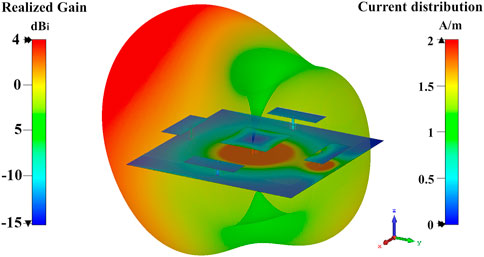
Figure 2. Contour current distribution and realized gain far-field distribution for a diode activated parasitic element.
Finally, the distance between central and parasitic elements was optimized in order to maximize the antenna realized gain in the directive configuration. The coupling in terms of surface current for three different distances is shown in Figure 3. The reflective behavior of the activated parasitic element is due to the current on the snap-fit PCB which is opposite to the one on feed and vias. Moreover, even if in Figure 3C the coupling between the central patch and the activated right parasitic element is stronger, it can be noticed that a higher amount of current spreads on the ground plane, either unwantedly participating in the coupling of other parasitic elements or increasing losses (Figure 3A). Instead, in Figure 3B the current is focused between the fed element and the shorted parasitic element. No interaction with the other parasitic elements or leaks on the ground plane occur, resulting in a greater realized gain.
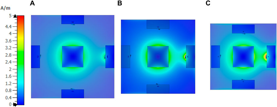
Figure 3. Comparison with coupling surface current in case of (A) 60 mm, (B) 47 mm, and (C) 35 mm distance between radiating and parasitic elements.
As a further confirmation, the variation of gain with respect to the parasitic element distance is presented in Figure 4, showing that the optimal relative placement can be found around 0.13
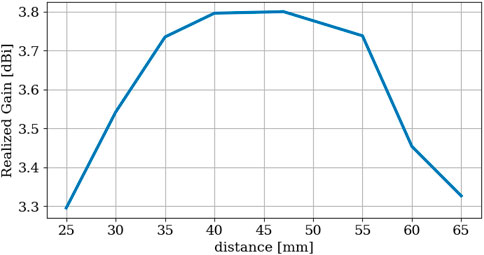
Figure 4. Realized gain variation compared to parasite distance between radiating and parasitic elements.
The optimized final design refers to the parameters reported in Table 1.

Table 1. Optimized antenna geometrical parameter values (in mm).
3 Numerical and experimental results
The optimized antenna structure was simulated using a CST Microwave Studio Electromagnetic simulator. The PIN diodes have been modeled according to the component datasheet as lumped elements, considering 100 mA and 2.1 V for forward-biased diodes and 0 V for reverse-biased diodes. The 100 nH RF-chokes have been also modeled as lumped elements.
A prototype of the proposed antenna system was manufactured and measured, and the results are compared with simulations. The prototype was equipped with an SMA connector to be measured with a Rohde and Schwarz Vector Network Analyzer and in a SATIMO StarLab system. As shown in Figure 5, the measured VSWR and total efficiency values are in good agreement with simulations. The measured total efficiency at 870 MHz amounts to 87.9%, and the measured VSWR is 32 MHz wide (for VSWR
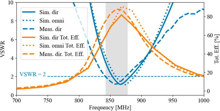
Figure 5. Simulated and measured comparison of VSWR and total efficiency when a directive beam is activated and in omnidirectional case.
The measured realized gain cut along the direction of the maximum in the directive case is presented in Figure 6A in comparison with the simulated one. Good agreement is visible, with a measured and simulated maximum gain of 3.95 dBi. Differences stand only for low values of the gain, and they can be addressed to the SMA cable and support of the measurement system. A demonstration of the conical coverage is presented in Figure 6B where an overlay of the four switchable directive gain beams is proposed. The intersection between consecutive configuration states is always greater than 3 dBi. Moreover, the difference between configurations in opposite directions is always greater than 4 dBi. The resulting 360
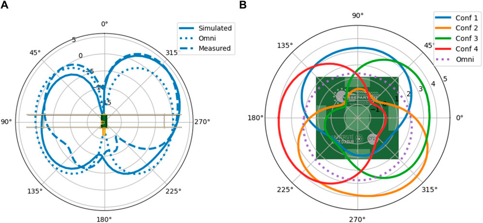
Figure 6. Simulated and measured realized gain
4 Transceiver integration
As part of an airborne-based portable terminal for real-time air quality monitoring, the antenna system has been conceived to house all the circuitry needed to send to ground the measured data using the LoRaWAN protocol. This choice was made to electrically and mechanically isolate the communication system from the drone and its payload. A board with an integrated ATmega328 microcontroller and RFM95 radio module (Ferrero, 2021) was thus fixed under the PCB used as ground-plane with the LoRa module RF output pin soldered to the central via of the antenna system, replacing the SMA connector. There are four couples of wires connecting the board to each snap-fit parasitic element shorting PCB in order to bias the lying diodes and electrically switch the beams (Figure 7). The board is powered by an external battery, also fixed on the back of the ground plane.
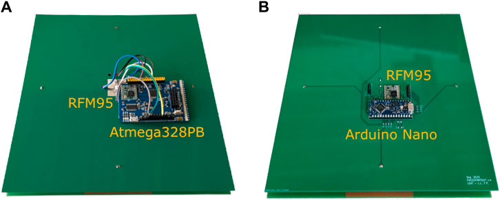
Figure 7. First version of Atmega328-based microcontroller (A) and PCB Arduino Uno version (B).
A further enhancement in the transceiver integration has been made with another version presented in Figure 7, where an Arduino Nano and RFM95 footprints have been directly included in the design of the ground plane PCB, together with the biasing lines for the snap-fit PCBs, which have been properly modified to bring the DC bias at both extremes of the diodes. This prototype reduces the interference due to free wires running through the structure, and it is more solid since all components are now soldered onto the PCB itself. The integration of the widely used Arduino Nano makes the design of this prototype a perfect candidate for low-cost, easy-to-assemble antenna for any IoT application using the 868 MHz frequency band.
5 On-field test
To practically evaluate the advantages of using the proposed antenna on UAVs for long range transmission, an open area test site was set (Figure 8) employing a hexacopter in line-of-sight (LoS) piloting.

Figure 8. Diagram of on-field test setup.
The testing system is based on the collection of RSSI samples during a LoRaPHI (LoRa-Alliance, 2023) packet exchange. Sampling was done at the ground station by the proposed reconfigurable antenna. Another copy of the antenna is mounted on the drone thanks to a 3D-printed supporting structure which guarantees a fair isolation with the metal parts that pertain to the drone (Figure 9). The antenna on the ground can reconfigure its radiation diagram as explained in the previous sections, while the one mounted on the drone is set to radiate omnidirectionally (all PIN diodes OFF).
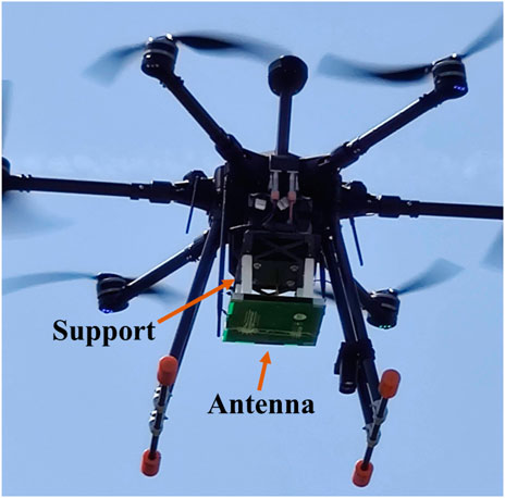
Figure 9. Photo of proposed antenna mounted on the hexacopter drone during the flight.
All collected samples were then combined with the drone flight positions at synchronous timestamps in post-processing. At each drone position, measurements were averaged over 15 samples collected every second.
During the on-field test, two different scenarios were considered: (a) the distance scenario, aimed at evaluating the communication performance when the drone moves away from the ground station, and (b) the rotation scenario, where the drone rotates around the ground station at fixed distance.
5.1 Distance scenario
In the first scenario, RSSI values were sampled for all ground antenna configurations along a straight-line drone path. The objective was to test communication performance over distance while maintaining a consistent relative antenna orientation (Figure 10). Due to LoS requirements and national flying regulations, the maximum distance was limited to approximately 350 m from the ground station and 50 m in height. Keeping the height constant at 45 m, this limitation resulted in the angle to the ground converging to 8
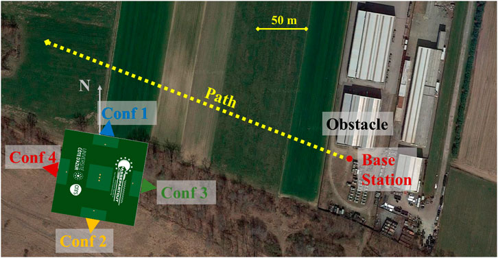
Figure 10. Path top view for measurement on distance referring to Conf 4. A reference of the base station antenna orientation and its location pointed in red.
Figure 11 shows a comparison of the collected RSSI measurements with the theoretical values calculated through the Friss formula for free/space propagation. These latter have been computed as Eq. 1:
where
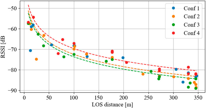
Figure 11. Averaged measured RSSI samples for each configuration compared to a qualitative free-space loss trend (dashed lines), respectively.
Measured RSSI data agree well with the theoretical values except for some outliers obtained for Conf 1 and Conf 2 and for distances smaller than 100 m. This behavior can be attributed to the multiple reflections and scattering phenomena caused by the proximity of a building across the direction of the respective reconfigurable beams.
As the distance from the ground station distance increases, the advantage given by the possibility of selecting the antenna configuration pointing at the drone is more evident. Conf 4 enables RSSI values that are, on average, 5 dB greater than the other configurations and almost 10 dB greater than those of Conf 3, which points in the opposite direction to the flight path.
5.2 Rotation scenario
The objective of the second on-field test scenario was to evaluate the use of steerable directive beams to provide the best physical channel. This was done by sampling RSSI values with the drone circling around the base station at a fixed altitude of 17.5 m and distance of 28 m.
The results obtained are depicted in Figure 12, which shows the RSSI values measured by each antenna configuration for all the different angular directions (the direction at 0
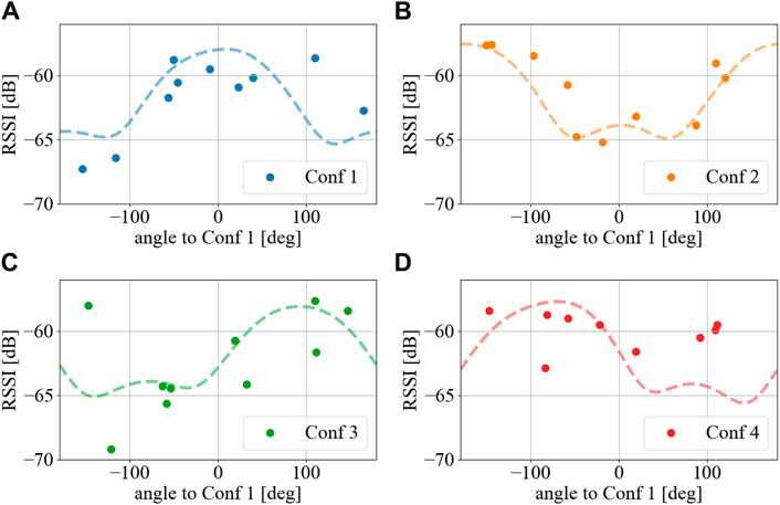
Figure 12. Averaged measured RSSI for each configuration compared to a qualitative radiation pattern shape over the same angles (dashed line). (A) Conf 1 samples compared to simulated directive gain shape along the correspondent direction. (B) Conf 2 samples compared to simulated directive gain shape along the correspondent direction. (C) Conf 3 samples compared to simulated directive gain shape along the correspondent direction. (D) Conf 4 samples compared to simulated directive gain shape along the correspondent direction.
Moreover, even if RSSI samples at such a small communication distance can be scattered (Figure 11), differences between opposite configurations are remarkable (about 5 dB between Conf 1 and Conf 2 at 0
6 Conclusion
A low profile, low cost, easy-to-assemble ESPAR design is here proposed to work at 868 MHz LoRa frequencies. Reflective coupling between active and parasitic elements were demonstrated thanks to the use of simple PIN diodes. The proposed antenna can develop a 3.95 dBi directive beam, and the combination of all directive beams can generate a conical beam coverage. Moreover, a dipole-like omnidirectional pattern is achievable when all PIN diodes are turned off. Conceived for drone-to-ground communications, it can be mounted on the drone as well as used on the ground stations.
An integration with the RF module and microcontroller on the same antenna structure is proposed to control the reconfigurable antenna in real case scenarios for LoRa applications.
On-field communication tests were performed to evaluate the advantages of the directive beam for coverage improvement and the reliability of the best physical channel choice when switching beams.
The results of this study show that the longer the distance, the higher the dominance of using a directive beam to receive power. Moreover, choosing the proper directive beam can improve channel reliability even at low distances, permitting overall increases of the measured RSSI level.
Data availability statement
The original contributions presented in the study are included in the article; further inquiries can be directed to the corresponding author.
Author contributions
FP: Writing–original draft, Methodology, Investigation, Conceptualization. LL: Writing–review and editing, Validation, Investigation. RS: Writing–review and editing, Supervision, Conceptualization.
Funding
The authors declare that financial support was received for the research, authorship, and/or publication of this article. This work has been supported by PASSEPARTOUT project, which received funding from the European Union’s Horizon 2020 research and innovation program under grant agreement No. 101016956.
Acknowledgments
The authors are thankful to Techno Sky Srl and Nimbus Srl for their technical and operational support on measurements with the drone.
Conflict of interest
The authors declare that the research was conducted in the absence of any commercial or financial relationships that could be construed as a potential conflict of interest.
Publisher’s note
All claims expressed in this article are solely those of the authors and do not necessarily represent those of their affiliated organizations, or those of the publisher, the editors and the reviewers. Any product that may be evaluated in this article, or claim that may be made by its manufacturer, is not guaranteed or endorsed by the publisher.
References
Badi, M., Wensowitch, J., Rajan, D., and Camp, J. (2020). Experimentally analyzing diverse antenna placements and orientations for uav communications. IEEE Trans. Veh. Technol. 69, 14989–15004. doi:10.1109/TVT.2020.3031872
Burtowy, M., Rzymowski, M., and Kulas, L. (2019). Low-profile espar antenna for rss-based doa estimation in iot applications. IEEE Access 7, 17403–17411. doi:10.1109/ACCESS.2019.2895740
Catarinucci, L., Guglielmi, S., Colella, R., and Tarricone, L. (2014). Pattern-reconfigurable antennas and smart wake-up circuits to decrease power consumption in wsn nodes. IEEE Sensors J. 14, 4323–4324. doi:10.1109/JSEN.2014.2360939
Choi, Y. S., and Lee, W. S. (2020). “Reconfigurable beam switching antenna with horizontal parasitic element reflector (hper) for uav applications,” in 2020 IEEE International Symposium on Antennas and Propagation and North American Radio Science Meeting, Montreal, QC, Canada, 05-10 July 2020, 433–434.
Choi, Y. S., Park, J. S., and Lee, W. S. (2020). Beam-reconfigurable multi-antenna system with beam-combining technology for uav-to-everything communications. Electronics 9, 980. doi:10.3390/electronics9060980
Cohn, P., Green, A., Langstaff, M., and Roller, M. (2017). Commercial drones are here: the future of unmanned aerial systems. Tech. rep., McKinsey Co. Available at: https://www.mckinsey.com/industries/travel-logistics-and-infrastructure/our-insights/commercial-drones-are-here-the-future-of-unmanned-aerial-systems.
Delaveaud, C., Leveque, P., and Jecko, B. (1994). New kind of microstrip antenna: the monopolar wire-patch antenna. Electron. Lett. 30, 1–2. doi:10.1049/el:19940057
Ferrero, F. (2021). UCA21. Tech. rep. Université côte d’Azur. Available at: Https://github.com/FabienFerrero/UCA21.
Harrington, R. (1978). Reactively controlled directive arrays. IEEE Trans. Antennas Propag. 26, 390–395. doi:10.1109/TAP.1978.1141852
Hayat, S., Yanmaz, E., and Muzaffar, R. (2016). Survey on unmanned aerial vehicle networks for civil applications: a communications viewpoint. IEEE Commun. Surv. Tutorials 18, 2624–2661. doi:10.1109/COMST.2016.2560343
Heslop, B. (2021). By 2030, each person will own 15 connected devices. here’s what that means for your business and content. Tech. Rep. Spiceworks.
Hossein Motlagh, N., Taleb, T., and Arouk, O. (2016). Low-altitude unmanned aerial vehicles-based internet of things services: comprehensive survey and future perspectives. IEEE Internet Things J. 3, 899–922. doi:10.1109/JIOT.2016.2612119
Kim, K. S., Yoo, J. S., Kim, J. W., Kim, S., Yu, J. W., and Lee, H. L. (2020). All-around beam switched antenna with dual polarization for drone communications. IEEE Trans. Antennas Propag. 68, 4930–4934. doi:10.1109/TAP.2019.2952006
Le, T. N., Pegatoquet, A., Le Huy, T., Lizzi, L., and Ferrero, F. (2016). Improving energy efficiency of mobile wsn using reconfigurable directional antennas. IEEE Commun. Lett. 20, 1243–1246. doi:10.1109/LCOMM.2016.2554544
LoRa-Alliance (2023). Lora and lorawan: technical overview. Tech. Rep. LoRa Alliance. Available at: https://lora-developers.semtech.com/documentation/tech-papers-and-guides/lora-and-lorawan/.
Mobilefish (2023). Lora documentation. Tech. Rep. LoRa Alliance. Available at: https://lora.readthedocs.io/en/latest/.
Pokorny, J., Ometov, A., Pascual, P., Baquero, C., Masek, P., Pyattaev, A., et al. (2018). Concept design and performance evaluation of uav-based backhaul link with antenna steering. J. Commun. Netw. 20, 473–483. doi:10.1109/JCN.2018.000072
Positano, F., Santamaria, L., Staraj, R., and Lizzi, L. (2023). “Low profile pattern reconfigurable espar for uavs in iot applications,” in 2023 17th European Conference on Antennas and Propagation (EuCAP), Florence, Italy, 26-31 March 2023, 1–4.
Santamaria, L., Ferrero, F., Staraj, R., and Lizzi, L. (2021a). Slot-based pattern reconfigurable espar antenna for iot applications. IEEE Trans. Antennas Propag. 69, 3635–3644. doi:10.1109/TAP.2020.3044399
Santamaria, L., Ferrero, F., Staraj, R., and Lizzi, L. (2021b). Electronically pattern reconfigurable antenna for iot applications. IEEE Open J. Antennas Propag. 2, 546–554. doi:10.1109/OJAP.2021.3073104
Keywords: reconfigurable antenna, parasite element array, pattern reconfigurable antenna, drone, RSSI, long range, ESPAR antenna
Citation: Positano F, Lizzi L and Staraj R (2024) Design and on-field test of ESPAR antenna for UAV-based long-range IoT applications. Front. Antennas Propag. 2:1429710. doi: 10.3389/fanpr.2024.1429710
Received: 08 May 2024; Accepted: 11 June 2024;
Published: 11 July 2024.
Edited by:
Wen-Jun Lu, Nanjing University of Posts and Telecommunications, ChinaCopyright © 2024 Positano, Lizzi and Staraj. This is an open-access article distributed under the terms of the Creative Commons Attribution License (CC BY). The use, distribution or reproduction in other forums is permitted, provided the original author(s) and the copyright owner(s) are credited and that the original publication in this journal is cited, in accordance with accepted academic practice. No use, distribution or reproduction is permitted which does not comply with these terms.
*Correspondence: Francesco Positano, francesco.positano@univ-cotedazur.fr