 Sima Noghanian
- CommScope Ruckus Networks, Sunnyvale, CA, United States
In WiFi 7 (IEEE 802.11be), Multiple Input Multiple Output (MIMO) technology plays a crucial role in enhancing throughput. This combination enables numerous applications for wearable WiFi devices. For instance, WiFi can be utilized for tracking and fall detection purposes. Additionally, wearable devices used in gaming, vital signal monitoring, and tracking can benefit from the implementation of wearable MIMO antennas. Despite the demand for wearable WiFi antennas, specifically in the new 6 GHz band, a significant gap exists in the investigation of antennas that are completely made of textile, are low profile, and provide vertical polarization and omnidirectional patterns. Addressing this gap, in this paper, a wearable planar antenna is introduced, which is specifically designed to offer an omnidirectional pattern and linear polarization. To ensure its practicality and ease of use, the antenna utilizes lightweight and wearable textile material. The design details and performance of the proposed antenna are presented. The antenna covers all three bands of WiFi, namely, 2.4 GHz, 5 GHz, and 6 GHz bands. The 10-dB return loss bandwidth is 2.4 GHz–2.5 GHz, and 4.6 GHz–7.2 GHz. The maximum Specific Absorption Rate (SAR) for an input power of 500 mW is calculated at 1.053 W/Kg for a 2 mm air gap between the antenna and tissue surface. The size of the antenna is given by a circular area of
1 Introduction
Wireless connectivity plays an integral role in our daily lives, and Wireless Local Area Network (WLAN) technology is a major contributor to providing this connectivity. With the increasing prevalence of sensors and Internet of Things (IoT) devices operating over WLANs, the significance of this technology has become even more apparent. Many WLANs operate based on the IEEE 802.11 standards, commonly known as WiFi networks.
Considering the growing focus on wearable wireless devices, establishing a direct connection to networks such as WiFi is highly desirable. This necessitates the development of wearable antennas operating in WiFi bands that can seamlessly integrate into clothing. The challenge lies in creating low profile, and preferably planar, antennas that can still maintain omnidirectional patterns, while also considering the potential impact of the lossy human tissue in their proximity on their performance. Additionally, it is crucial to mitigate the radiation directed toward the body, as high radiated power levels can lead to a high Specific Absorption Rate (SAR), requiring a reduction in input power to comply with SAR regulations.
The objective of this work was to design a compact antenna that exhibits good isolation from the wearer’s body, with a specific focus on WiFi 7 applications. WiFi 7, also known as 802.11be, has introduced new frequency bands to enhance wireless communication. Traditionally, WiFi operates in the 2.4 GHz and 5 GHz frequency bands. These frequency bands have been widely used and supported by various WiFi devices. However, due to the increasing demand for faster and more reliable wireless connections, new frequency bands are added in WiFi 7. One frequency band that is adopted by WiFi 7 is the 6 GHz band, also known as the 6E band. The 6E band offers a significant amount of unlicensed spectrum, which allows for higher bandwidth and reduced interference compared to the congested 2.4 GHz and 5 GHz bands. Overall, the use of wider frequency bands is a major advantage of WiFi 7. It will allow WiFi 7 to achieve much higher data rates, and it will also help to improve performance in crowded environments.
WiFi frequency bands include 802.11 a/b/g/n/ac/ax/be bands: 2.401–2.484 GHz (referred to as 2.4 GHz), 5.170–5.835 GHz (referred to as 5 GHz), and 5.925–7.125 GHz (referred to as 6 GHz). The WiFi network technology takes advantage of pattern and polarization diversity. In each WiFi Access Point (AP) often vertical and horizontal polarization antennas are employed. This is in conjunction with the MIMO antennas that may use polarization diversity. By leveraging spatial diversity, where multiple antennas experience different propagation paths, MIMO systems can overcome signal degradation caused by reflections and interference. Additionally, MIMO antennas can create higher throughput by employing spatial multiplexing, transmitting independent data streams through different antenna elements simultaneously.
The goal of this paper was to design a wearable antenna that can cover all three bands. Specifically in this paper, the interest was to use all-textile material to provide a light and low-profile antenna that can seamlessly be integrated into clothing. Various options exist for creating textile antennas with broadside radiation patterns (maximum power radiation perpendicular to the plane of the antenna). There is also interest in developing antennas with patterns with a null at the broadside angle and vertical polarization to enhance pattern and polarization diversity. Such a pattern is particularly useful for on-body communication, where the antenna radiates toward a wearable device, or when the antenna communicates with a WiFi AP located on the ceiling or at a point on the wall that is higher than the height of the person wearing the antenna. In these situations, the maximum beam angle of around 30°–60° from the broadside angle is desired. The objective of this work was to design an antenna that provides a monopole-like pattern with a null at the broadside angle.
There is a rich literature on the topic of textile antennas (Yan et al., 2015; Mantash et al., 2016; Yang et al., 2016; Alemaryeen and Noghanian, 2018b; Alemaryeen and Noghanian, 2018a; Alemaryeen and Noghanian, 2019; Ali et al., 2021; Ali et al., 2022; Noghanian, 2022). Table 1 summarizes some of the antennas that are textile-based and work in the frequency band close to one or multiple bands of WiFi. Most of these antennas, however, are not specifically covering the 6E band.
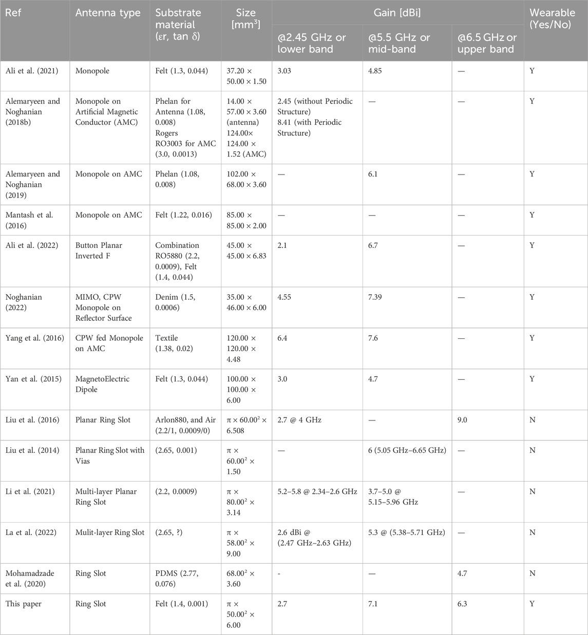
Table 1. Comparing different wearable and non-wearable antennas proposed in the literature and this paper.
In (Liu et al., 2016) a wideband monopole-like antenna with 36.5% bandwidth that covers the band of 4.25–6.15 GHz is proposed. The gain varies from 2.7–9.7 dBi in the band. They suggest the use of an air substrate of 6 mm and a thin rigid substrate, Arlon880, with a thickness of 0.508 mm, with an overall radius of substrates and ground layers of 60 mm. In Liu et al. (2014) a similar structure with coaxial feeding at the center is suggested, but two modes of operation are created: TM01 (through via structures) and TM02 (through the annular slot). The antenna covers the bandwidth of 5 GHz–6.75 GHz with a gain of around 2.5 dBi at 5 GHz and around 6 dBi at 6.5 GHz. Some papers suggest multi-layer structures. Such as those presented in Li et al. (2021) and La et al. (2022). In this case, each layer may cover one frequency band. The use of multi-layer usually involves vias that only go through one or two layers. Although the multi-layer design may be low profile and cover multiple frequency bands, the via structure is complicated. A flexible design is proposed in Mohamadzade et al. (2020) that uses a ring slot structure with vias and two rectangular slots. The structure is built on a flexible substrate by pouring PDMS into a customized ring-shaped mold. The conductive part of the antenna was a conductive fabric of nickel-copper ripstop from Less EMF Inc. The 3 mm thick substrate had εr = 2.77 and tan δ = 0.076. E-textile had a thickness of 0.6 mm. The rectangular slots were introduced to create a notched band from 5 to 6 GHz. The vias were realized by using copper pins that were added after curing the PDMS layer. Although the antenna is flexible, it is not fully textile-based and it does not cover the WiFi bands. The use of this antenna as a wearable one, in the proximity of the human body was not addressed in the paper. For more details about the above antennas please refer to Table 1.
In this paper, a fully textile antenna is designed to cover all WiFi bands, including 2.45 GHz, 5 GHz, and 6 GHz. The presence of the body was considered by assuming a tissue block with a relative permittivity of (εr) 28, a conductivity of 4 S/m, and a loss tangent (tan δ) of 0.1 while maintaining a 2 mm air gap. One unique feature is that all three bands’ operations are achieved with a single feed. To create a multiband antenna with a single feed one may use different resonances by shaping the radiative element (Zahid et al., 2022), alternatively, by properly exciting the higher-order modes different resonances can be created (Iqbal et al., 2022). In this paper, the second approach was used.
The remaining parts of this paper are organized as follows. Firstly, the structure of the antenna is explained in detail, providing a comprehensive understanding of the radiation mechanism and design considerations. Next, the paper reports the effects of the substrate material and the number and location of vias. Furthermore, the paper investigates the effects of bending on the antenna’s performance, including variations in the gain, and matching across different scenarios. Subsequently, the measurement results obtained from the fabricated antenna are presented and analyzed.
2 Antenna design and performance
2.1 Antenna structure
The textile material is an ideal choice for wearable antennas since it provides a lightweight and flexible antenna that can easily be integrated with clothing. In the case of WiFi applications, the antenna should have an omnidirectional pattern and achieve maximum gain between angles of 30°–60° from the vertical axis. This ensures optimal coverage by the AP. The purity of the polarization helps to take the most advantage of polarization diversity.
To meet these requirements, a 6 mm thick felt substrate was considered. The conductive ground plane and patch are made using an e-textile. The overall diameter of the antenna, including the textile ground plane, is 100 mm. The antenna consists of concentric rings and a small central patch. Figure 1 shows the antenna structure. The center patch acts as proximity feeding, exciting TM0n modes. The radii of the ring slots are optimized to cover the three required WiFi bands.
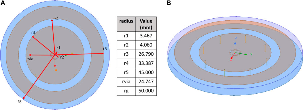
Figure 1. Proposed triple band antenna structure: (A) Top view of the antenna, all dimensions are given in mm; (B) Vias added to the outer side of the first ring with 2 mm distance from the edge of the ring.
The design started with the assumption of the felt substrate with the relative permittivity of εr = 1.4 and loss tangent of tan δ = 0.001. The antenna was placed on a block of average tissue material. The dielectric constant of the average tissue was set to εr = 28 and the loss tangent was assumed to be tan δ = 0.1 with a bulk conductivity of σ = 4 S/m. The distance between the ground plane of the antenna and the surface of the skin is shown as air_gap. The dimensions of the average tissue block and the placement of the antenna on the tissue block are shown in Figure 2. All simulations in this paper are done by ANSYS Electronics Desktop 2022.R2. In all the simulations the feeding was done through a lumped port in ANSYS HFSS. Section 3 provides the measurement results where the feeding was done through a coaxial cable attached to an SMA connector.
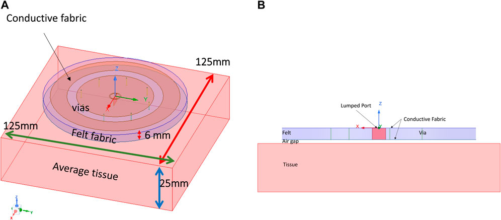
Figure 2. The antenna was placed on a block of average tissue: (A) Tissue block and antenna placement; (B) Side view, all dimensions are in mm.
2.2 Radiation mechanism
The basic operation of this antenna is to use multiple TM0n modes of an annular array with a center feed. By controlling the excited modes, the frequency band can be determined. To excite TM01 mode the center frequency of 4.2 GHz was considered, and the central patch radius was calculated by Equation 1:
where
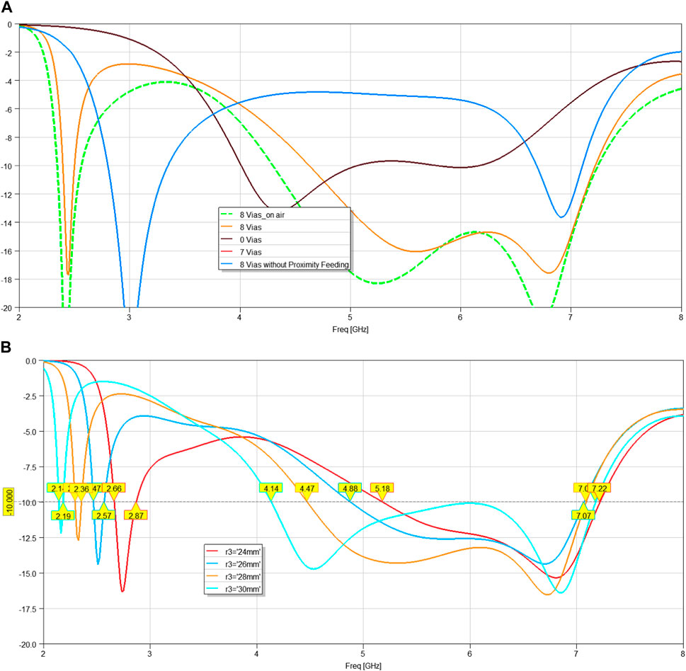
Figure 3. Reflection coefficient (S11) variation with (A) different number of vias; (B) ring and via radius; substrate thickness was 6 mm and air_gap was 2 mm.
2.3 Current distribution and radiation patterns
To understand the antenna radiation mechanism better, the E-field for the four selected frequencies is shown in Figures 4A–D. The field distribution shows TM01 mode for 2.4 GHz and TM02 mode for higher frequencies. For the final design, S11 with and without the assumption of the average tissue block is shown in Figures 4E. As seen in Figure 4E, the effect of tissue block on matching is not significant.
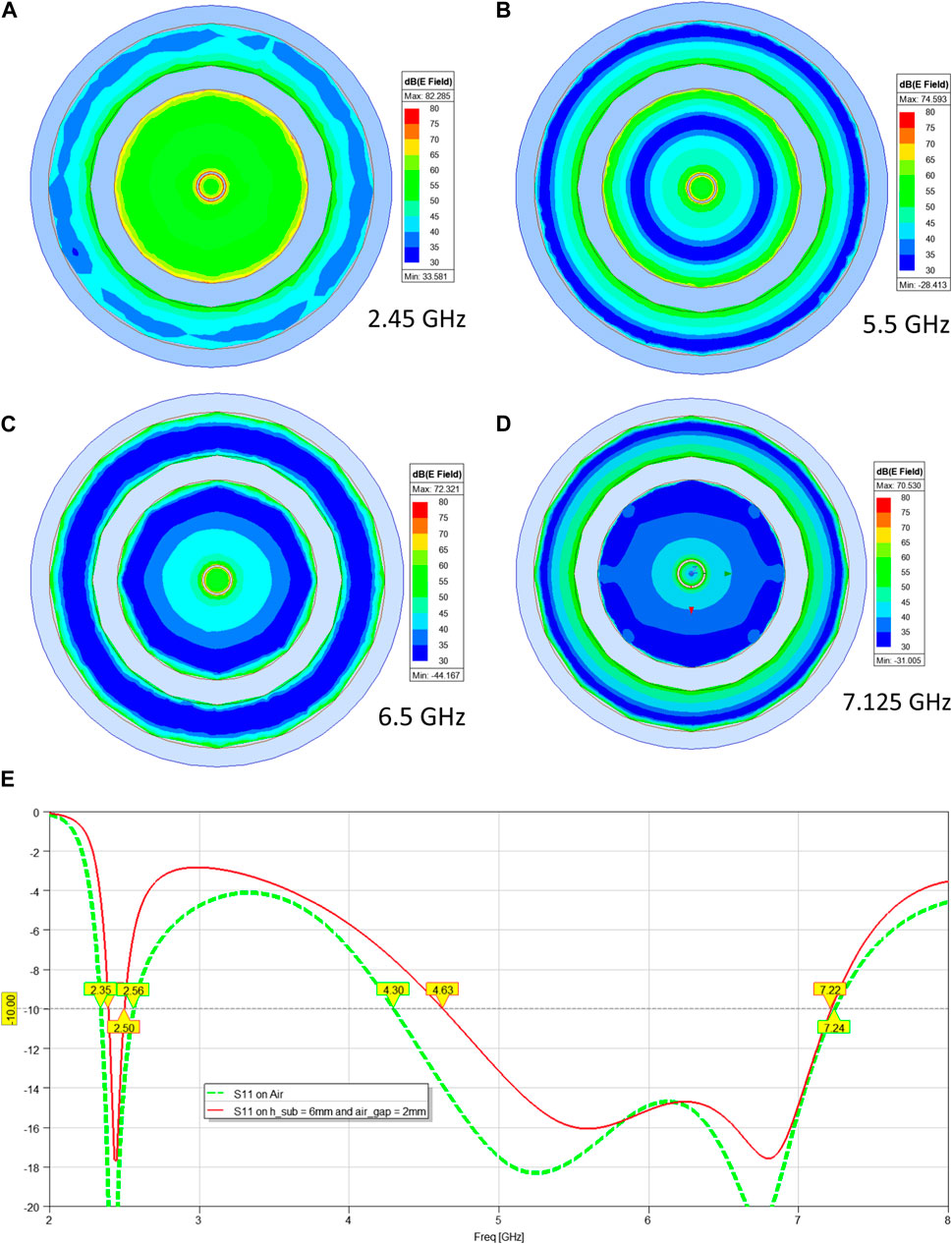
Figure 4. (A–D) E-field; (E) final design, reflection coefficient (S11) on air and the average tissue block.
Some of the radiation patterns in two orthogonal planes (ϕ = 0° and 90°) are shown in Figure 5. The similarity between the patterns in the orthogonal planes shows the antenna maintains omnidirectionality over a wide range of frequencies.
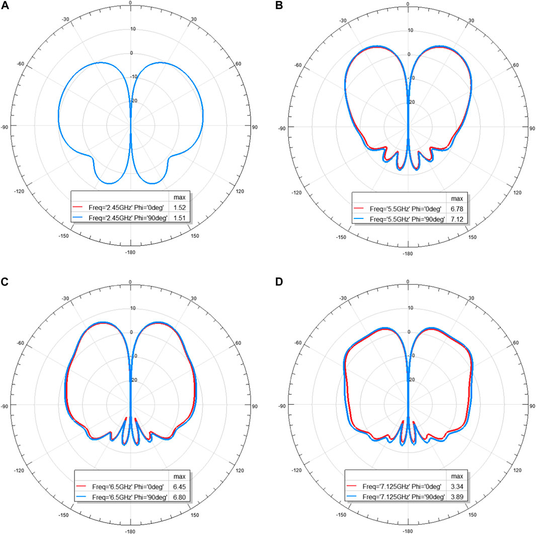
Figure 5. Radiation patterns for the antenna on ϕ = 0° (red) and 90° (blue). The antenna has a 6 mm substrate with a 2 mm air gap: (A) 2.45 GHz; (B) 5.5 GHz; (C) 6.5 GHz; (D) 7.125 GHz (Cross polarization level in all cases was lower than −30 dBi).
2.4 Substrate thickness and air gap effects
Considering the low permittivity of the substrate, the thickness of the substrate can have significant effects on the bandwidth, especially in the bands of 5 GHz and 6 GHz. While the thinner substrate is preferred, the reduction of substrate thickness (h_sub) can significantly reduce the matching bandwidth, as shown in Figure 6A. The suitable thickness that can provide the bandwidth coverage for all three bands of WiFi was found to be h_sub = 6 mm.
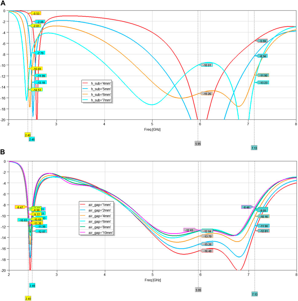
Figure 6. Reflection coefficient (S11) variation with (A) substrate thickness (air_gap = 2 mm); and (B) air_gap (h_sub = 6 mm).
On the other hand, due to the presence of the ground plane, the matching was not significantly affected by the change in the air gap between the antenna and the tissue layer (air_gap). This variation is shown in Figure 6B. To consider a separation created by the air-gap and clothing, for the remainder of the study an air_gap of 2 mm was assumed.
2.5 Specific absorption rate (SAR) and gain
In the United States, the Federal Communications Commission (FCC) regulates SAR limits for wireless devices. The FCC has set a maximum SAR limit of 1.6 W per kilogram (W/kg), averaging over 1 gram (g) of tissue. Given the focus on wearable WiFi applications, it is crucial to investigate the SAR under various conditions for this antenna. To assess its performance, we examined the gain, SAR (in W/Kg), antenna radiation efficiency, and bandwidths for a 6 mm substrate thickness with an air gap of 2 mm. The results, based on a 500-mW input power, are summarized in Table 2. The SAR distributions are depicted in Figure 7. The results in Figure 7 and Table 2 indicate that the maximum SAR value is given for the highest frequency of 7.125 GHz. Keeping the input power at 500 mW, these values are below the maximum required by FCC (1.6 W/Kg) taken over a volume of 1 g of tissue mass. They are also below the limit dictated by ICNIRP (International Commission on Non-Ionizing Radiation Protection) guidelines which is 2 W/Kg taken over a volume of 10 g of tissue mass. Table 2 shows a maximum 1-g average SAR of 1.053 W/Kg and a 10-g average SAR of 0.542 W/Kg.
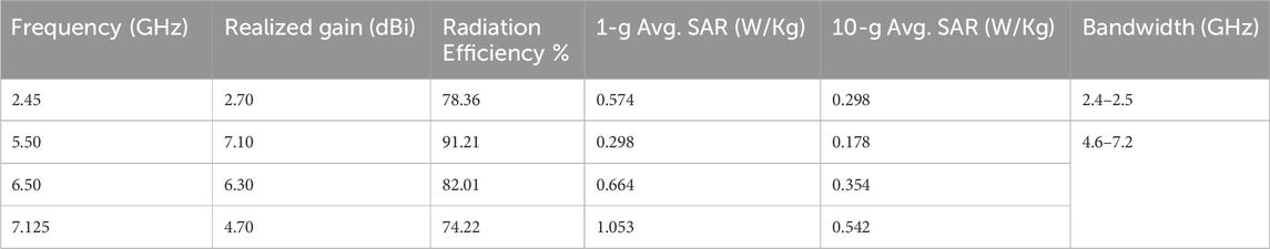
Table 2. Antenna gain, bandwidth, and 1-g and 10-g average SAR summary for an input power of 500 mW.
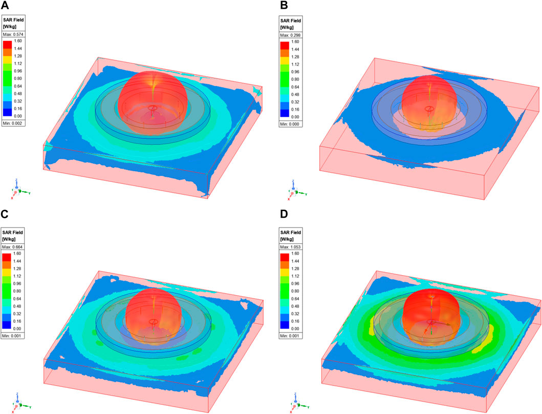
Figure 7. SAR distribution for an antenna on a block of average tissue, using 1-g average SAR and input power for 500 mW at (A) 2.45 GHz; (B) 5.5 GHz; (C) 6.5 GHz; (D) 7.125 GHz.
2.6 Bending effects
When the antenna is positioned on the wearer’s body, it may undergo bending. To account for this phenomenon, we specifically examined the impact of bending. To simulate the bending effect, we employed a cylindrical tissue block with a radius of "h_tissue.” To create an air gap, a 2 mm cylindrical shell of air was introduced, followed by the addition of the ground layer, substrate, and antenna conductive patch and rings. Figure 8A illustrates the simulation setup along with four radiation patterns corresponding to h_tissue = 80 mm. Furthermore, Figure 8B demonstrates the effect of bending on the reflection coefficient, comparing it with a flat antenna on a 2 mm air gap and 6 mm substrate thickness. Lastly, Figure 8C presents the influence of bending on the gain, varying h_tissue from 50 mm to 100 mm.
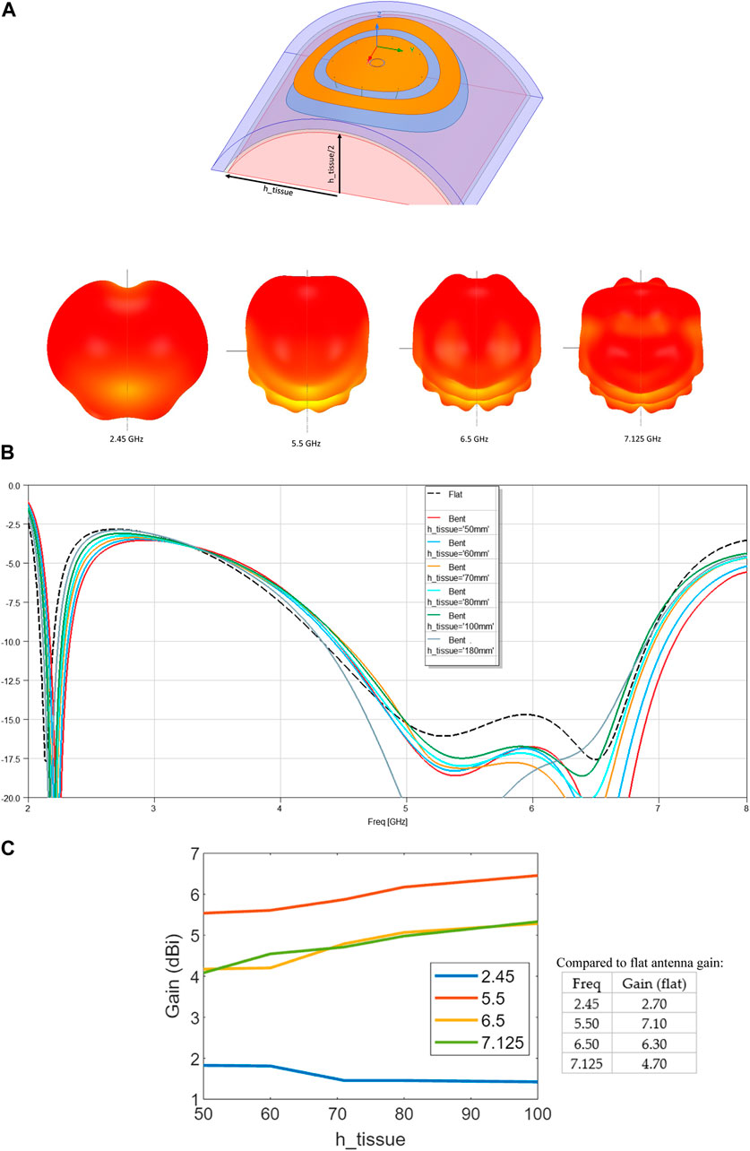
Figure 8. Antenna performance under bending condition (simulation): (A) Bending profile; (B) S11; (C) gain under various bending.
Figure 9 shows the radiation patterns, on ϕ = 0° and ϕ = 90° planes, for various frequencies. The similarity of the patterns in the two orthogonal planes shows that the antenna has kept its omnidirectionality. The patterns are less affected by bending up to around 6.5 GHz.
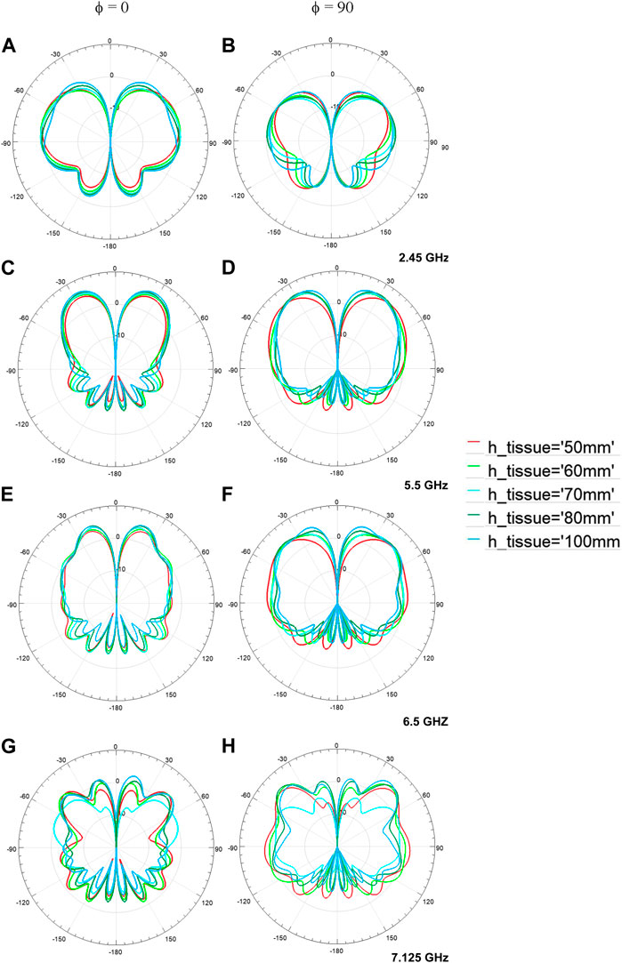
Figure 9. Simulated radiation patterns, on ϕ = 0° and ϕ = 90° planes, for different bending conditions at (A, B) 2.45 GHz; (C, D) 5.5 GHz; (E, F) 6.5 GHz; (G, H) 7.125 GHz.
3 Measurement results
3.1 Antenna fabrication
A 6 mm thick felt material from heavy-duty felt sheets by RERIVER was used as the substrate, and e-textile fabric by Ohwekit was used for the conductive parts. The vias were created by AGSIS highly conductive silver-coated nylon threads. The photo of the fabricated antenna and the conductive thread is shown in Figure 10A. The measured S11 for the fabricated antenna on the heavy-duty felt substrate is demonstrated and compared with the simulated one in Figure 10B. A good agreement is observed. The simulation showed that antenna matching and performance are not much affected by the body tissue. Therefore, antenna matching, patterns, and gain measurement were done in free space (on air). A Copper Mountain Vector Network Analyzer and MVG Star Lab were used for these patterns and gain measurements.
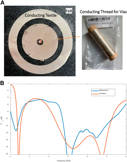
Figure 10. (A) The fabricated antenna on the heavy-duty felt and conducting thread; (B) S11 measured on air, compared with the simulation results.
3.2 Measured gain and radiation patterns
The radiation patterns and gain of the antenna were measured at different frequencies using an MVG StarLab antenna measurement system. After the gain measurements, it was discovered that the losses in the antenna exceeded the assumptions made in the simulation. This was primarily attributed to the high loss characteristics of the substrate material, which exhibited greater losses compared to regular felt fabric. Table 3 presents a comparison between the initial simulation substrate and a substrate that closely matched the measured results. To confirm the loss assumption, a comparison between the measured S21 for a short microstrip line on the heavy-duty felt with a simulation is presented in the last column of Table 3. The results show that the loss tangent of 0.09 provides a simulation result that is closer to the measured S21. The antenna simulation was modified to account for the higher losses. The measured and simulated radiation patterns are depicted in Figure 11 for comparison. Figure 12A provides a comparison of the overall efficiency between the heavy-duty felt antenna, and the adjusted simulation results (with the substrate with a tan δ of 0.009). Figure 12B shows the comparison between measured and simulated gain.
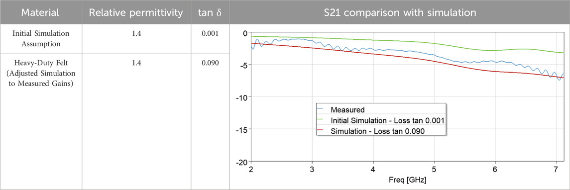
Table 3. Substrate material properties.
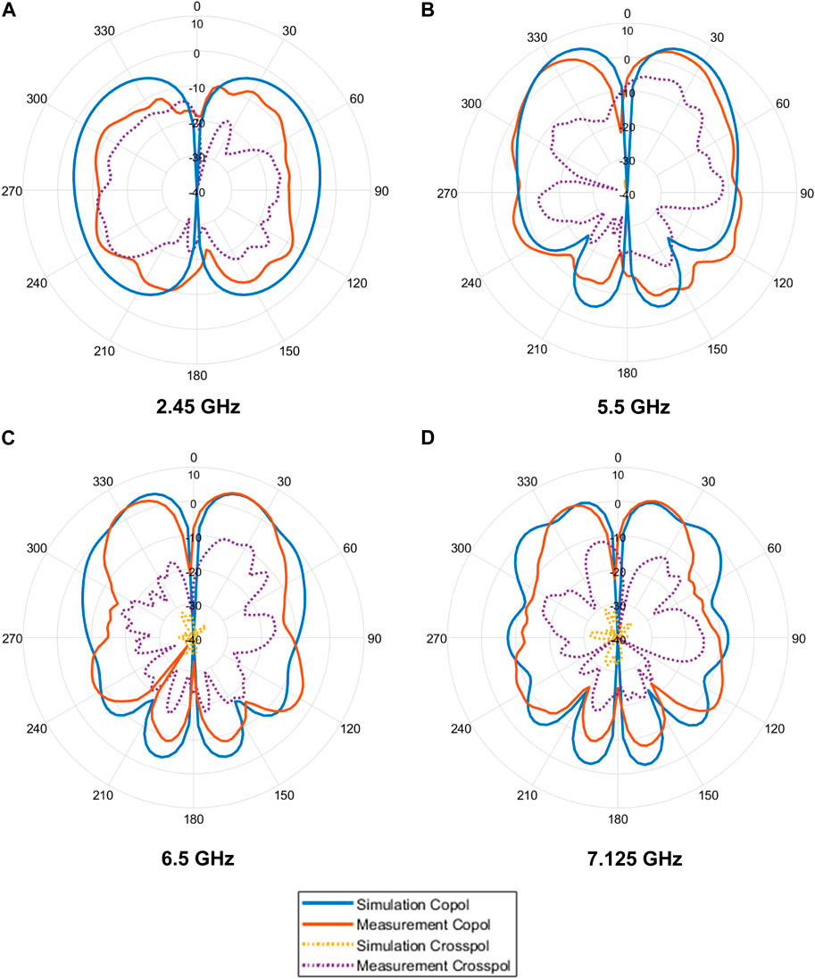
Figure 11. Pattern measurements vs simulations at different frequencies, (A) 2.45 GHz, (B) 5.5 GHz, (C) 6.5 GHz, and (D) 7.125 GHz.
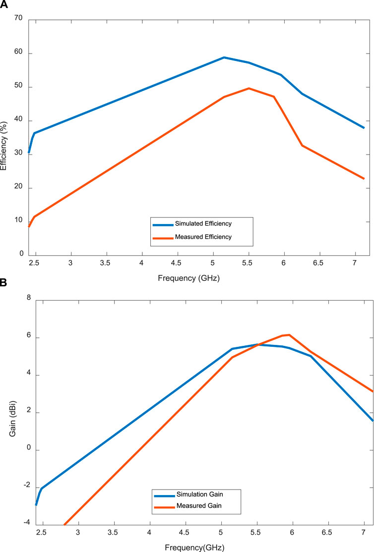
Figure 12. Simulated and measured (A) efficiency; and (B) gain.
4 MIMO antennas
MIMO antennas are crucial technology in wireless communication, particularly in WiFi networks. To be able to provide the throughput for high-speed applications, WiFi technology relies on various diversity such as space and polarization diversities. In WiFi systems, MIMO technology utilizes multiple antennas at the APs and often the stations (STAs). To increase the diversity of MIMO channels, antennas with space diversity and polarization diversity are utilized. Space diversity involves placing antennas at different locations to exploit the spatial variations of the wireless channel. On the other hand, polarization diversity utilizes antennas with different polarizations to create orthogonal channels, further enhancing signal separation and reducing interference. One of the motivations for designing the proposed antenna was to create a vertical-type polarization that can be combined with horizontally polarized antennas such as the one the author proposed in Noghanian (2022). The advantage of the wearable textile antenna is that it can be distributed over the body and create a space diversity MIMO.
The performance of the proposed wearable antenna was assessed in MIMO settings using ANSYS Electronics Desktop (AEDT 2022R2) SBR+ (Shooting Bouncing Rays) simulations. In the analysis, a small indoor office environment with an AP on the ceiling is considered (Figure 13). The office contains objects like doors, walls, chairs, and tables made of different materials such as glass, wood, and metal. The AP in the study is equipped with two antennas, offering two polarizations. For the MIMO analysis, the antennas on AP include two dipoles operating at the related frequency. For each configuration of MIMO, dipoles at 2.45 GHz, 5.5 GHz, 6.5 GHz, or 7.125 GHz were placed on the ceiling. Two wearable antennas are positioned on the front of the chest at a height of 1.15 m and on the back at a height of 1 m of a human body model filled with the average tissue material. The human body is then moved along predefined paths, referred to as path x and path y. The AP antennas and the wearable antennas are creating a combination to realize a 2 × 2 MIMO configuration.
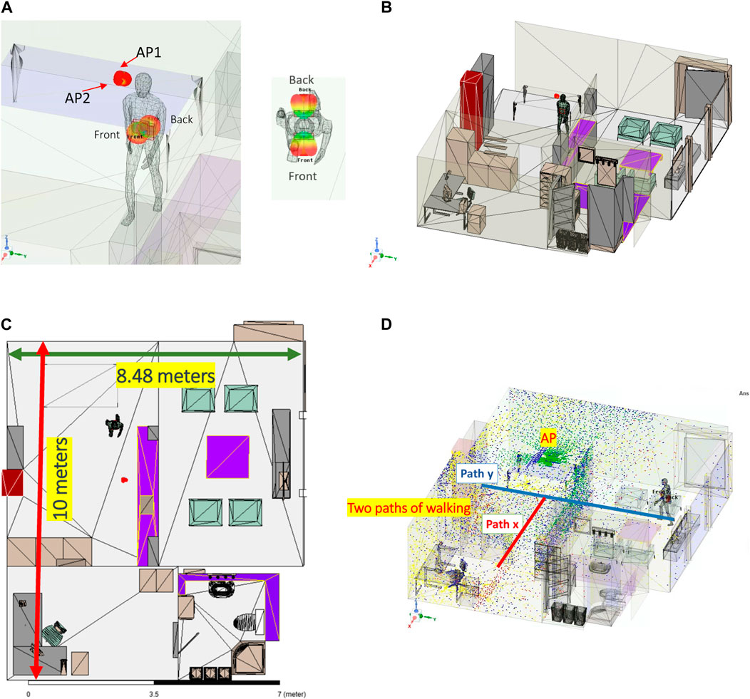
Figure 13. SBR+ simulation setup: (A) Two textile antennas were placed on a human body model; (B) The human model indoor office area moved on two paths; (C) Office area dimensions and the paths of moving the body; (D) Visual ray trace, dots with different colors represent the path of reflected rays.
These simulations enable an assessment of the performance and efficacy of the proposed wearable antennas under different MIMO setups. Factors such as the surrounding environment, human body effects, and antenna placement are taken into consideration during the evaluation. The channel matrix (H) was created using the
where
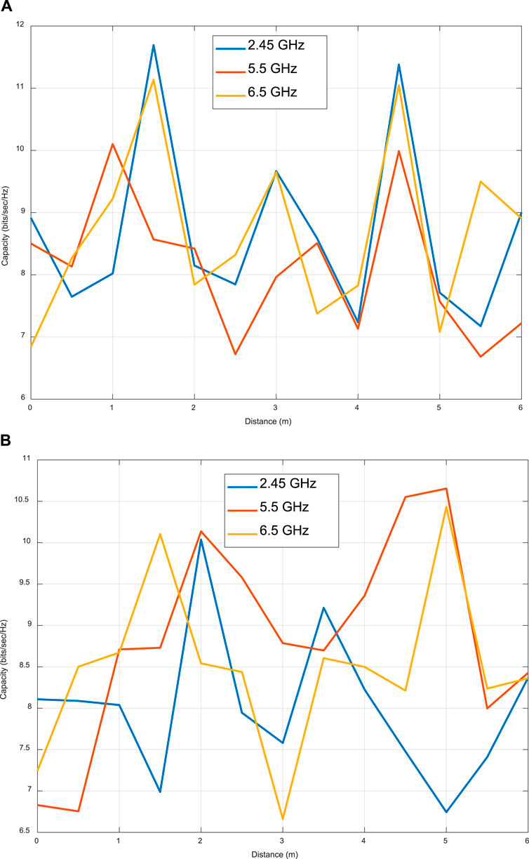
Figure 14. Capacity calculated for MIMO settings with an assumed SNR of 23 dB. (A) X Path; (B) Y Path.
5 Conclusion
A novel wearable antenna designed to cover all three WiFi bands was presented. The antenna features a simple and symmetric design, resulting in a desirable omnidirectional radiation pattern. Made from fabric and conducting threads, the antenna offers a low-profile structure that facilitates easy integration into garments such as jackets.
The performance of the antenna was thoroughly investigated under various bending conditions. The results demonstrate that the antenna maintains its functionality and effectiveness even when subjected to bending. Furthermore, the SAR based on the 1-g tissue average aligns with the regulations set by the FCC, ensuring compliance for an input power of 500 mW. The maximum calculated 1-g average SAR at 7.125 GHz is 1.053 W/Kg for an input power of 500 mW.
The antenna was fabricated using e-textile and heavy-duty felt sheets. The vias were created using highly conductive silver-coated nylon threads. The measured gains are −5.4 dBi, 5.6 dBi, 5.25 dBi, and 3.12 dBi at 2.45 GHz, 5.5 GHz, 6.5 GHz, and 7.125 GHz, respectively.
The shooting bouncing ray simulation of a 2 × 2 MIMO antenna set created on the body showed of 5%–15% capacity improvement over a SISO system. The proposed wearable antenna design offers the possibility of placement in different locations on the body, enabling the creation of diverse MIMO sets. The antenna’s capability to provide increased distance facilitates the achievement of space diversity, a feature that is challenging to attain with compact MIMO antennas, commonly found in handheld or small portable devices.
Data availability statement
The original contributions presented in the study are included in the article/Supplementary Material, further inquiries can be directed to the corresponding author.
Author contributions
SN: Conceptualization, Data curation, Formal Analysis, Funding acquisition, Investigation, Methodology, Project administration, Resources, Software, Supervision, Validation, Visualization, Writing–original draft, Writing–review and editing.
Funding
The author declares that no financial support was received for the research, authorship, and/or publication of this article.
Acknowledgments
The support through the use of equipment of CommScope Ruckus Networks, and the help of Ms. Tiffany Ton (CommScope) in fabrication, are acknowledged.
Conflict of interest
Author SN was employed by CommScope Ruckus Networks.
The author declared that they were an editorial board member of Frontiers, at the time of submission. This had no impact on the peer review process and the final decision.
Publisher’s note
All claims expressed in this article are solely those of the authors and do not necessarily represent those of their affiliated organizations, or those of the publisher, the editors and the reviewers. Any product that may be evaluated in this article, or claim that may be made by its manufacturer, is not guaranteed or endorsed by the publisher.
References
Alemaryeen, A., and Noghanian, S. (2018a). “A wideband antenna for biotelemetry applications: design and transmission link evaluation,” in 2018 International Applied Computational Electromagnetics Society Symposium (ACES), Denver, CO, 1–12. doi:10.23919/ROPACES.2018.8364246
Alemaryeen, A., and Noghanian, S. (2018b). Crumpling effects and specific absorption rates of flexible AMC integrated antennas. IET Microwaves, Antennas Propag. 12, 627–635. doi:10.1049/iet-map.2017.0652
Alemaryeen, A., and Noghanian, S. (2019). On-body low-profile textile antenna with artificial magnetic conductor. IEEE Trans. Antennas Propag. 67, 3649–3656. doi:10.1109/TAP.2019.2902632
Ali, S. M., Sovuthy, C., Noghanian, S., Ali, Z., Abbasi, Q. H., Imran, M. A., et al. (2021). Design and evaluation of a flexible dual-band meander line monopole antenna for on-and off-body healthcare applications. Micromachines (Basel) 12, 475. doi:10.3390/mi12050475
Ali, S. M., Sovuthy, C., Noghanian, S., Saeidi, T., Majeed, M. F., Hussain, A., et al. (2022). Design and evaluation of a button sensor antenna for on-body monitoring activity in healthcare applications. Micromachines (Basel) 13, 475. doi:10.3390/mi13030475
Foschini, G. J., and Gans, M. J. (1998). On limits of wireless communications in a fading environment when using multiple antennas.
Iqbal, J., Illahi, U., Khan, M. A., Rauf, A., Ali, E. M., Bari, I., et al. (2022). A novel single-fed dual-band dual-circularly polarized dielectric resonator antenna for 5G sub-6GHz applications. Appl. Sci. Switz. 12, 5222. doi:10.3390/app12105222
La, D. S., Zhao, J. H., Chen, S. M., Zhang, C. X., Qu, M. J., and Guo, J. W. (2022). Dual-band omnidirectional coupled-fed monopolar filtering antenna. Eng. Sci. Technol. Int. J. 35, 101188. doi:10.1016/j.jestch.2022.101188
Li, Y. C., Tu, H. H., Wang, K. X., Xue, Q., and Wong, H. (2021). A low-profile dual-band coaperture monopolar antenna based on cross-layer folded structure. IEEE Trans. Antennas Propag. 69, 6936–6940. doi:10.1109/TAP.2021.3076355
Liu, J., Zheng, S., Li, Y., and Long, Y. (2014). Broadband monopolar microstrip patch antenna with shorting vias and coupled ring. IEEE Antennas Wirel. Propag. Lett. 13, 39–42. doi:10.1109/LAWP.2013.2295686
Liu, S., Wu, W., and Fang, D. G. (2016). Wideband monopole-like radiation pattern circular patch antenna with high gain and low cross-polarization. IEEE Trans. Antennas Propag. 64, 2042–2045. doi:10.1109/TAP.2016.2536418
Mantash, M., Tarot, A. C., Collardey, S., and Mahdjoubi, K. (2016). Design methodology for wearable antenna on artificial magnetic conductor using stretch conductive fabric. Electron Lett. 52, 95–96. doi:10.1049/el.2015.3135
Mohamadzade, B., Simorangkir, R. B. V. B., Hashmi, R. M., Chao-Oger, Y., Zhadobov, M., and Sauleau, R. (2020). A conformal band-notched ultrawideband antenna with monopole-like radiation characteristics. IEEE Antennas Wirel. Propag. Lett. 19, 203–207. doi:10.1109/LAWP.2019.2958036
Noghanian, S. (2022). Dual-band wearable MIMO antenna for WiFi sensing applications. Sensors 22, 9257. doi:10.3390/s22239257
Yan, S., Soh, P. J., and Vandenbosch, G. A. E. (2015). Wearable dual-band magneto-electric dipole antenna for WBAN/WLAN applications. IEEE Trans. Antennas Propag. 63, 4165–4169. doi:10.1109/TAP.2015.2443863
Yang, H., Yao, W., Yi, Y., Huang, X., Wu, S., and Xiao, B. (2016). A dual-band low-profile metasurface-enabled wearable antenna for WLAN devices.
Keywords: WiFi antennas, textile antennas, MIMO antennas, WiFi 7, omnidirectional antenna
Citation: Noghanian S (2024) Textile omnidirectional antenna for wearable WiFi-7 applications using higher order modes. Front. Antennas Propag. 2:1419391. doi: 10.3389/fanpr.2024.1419391
Received: 18 April 2024; Accepted: 19 June 2024;
Published: 03 September 2024.
Edited by:
Bal Virdee, London Metropolitan University, United KingdomReviewed by:
Mohammad Alibakhshikenari, Universidad Carlos III de Madrid, SpainRoy Simorangkir, University College Cork, Ireland
Copyright © 2024 Noghanian. This is an open-access article distributed under the terms of the Creative Commons Attribution License (CC BY). The use, distribution or reproduction in other forums is permitted, provided the original author(s) and the copyright owner(s) are credited and that the original publication in this journal is cited, in accordance with accepted academic practice. No use, distribution or reproduction is permitted which does not comply with these terms.
*Correspondence: Sima Noghanian, c2ltYV9ub2doYW5pYW5AaWVlZS5vcmc=