- 1Department of Mechanical Engineering, Tokyo University of Technology, Hachioji, Japan
- 2Teral Inc, Fukuyama, Japan
- 3Graduate School of Engineering, Chiba University, Chiba, Japan
Drones, which have become increasingly popular in recent years, produce a lot of noise due to the movement of their propellers. When flying near humans, especially as in urban situations, noise suppression is critical. It has been demonstrated that noise can be minimized by increasing propeller lift per unit rotation speed and decreasing propeller rotation speed by expanding propeller area or designing the airfoil shape. This study developed a new structure, serrated Gurney flap, by merging the Gurney flap, which is the trailing-edge structure of an airfoil, and the serration, which is the low-noise structure found in an owl feather, and studied its performance through experiments and numerical simulations. The results indicated that the structure can boost the propeller’s lift coefficient while reducing the vortex separation induced by the Gurney flap and suppress propeller noise by slowing the propeller. Further modification of its structure may result in improved efficiency as well as decreased noise level.
1 Introduction
Drones have become increasingly popular in recent years for a variety of purposes such as surveillance and deliveries (Rothstein, 2015; Nonami, 2016). Because drones are expected to fly around cities or be used for acoustic surveillance, their noise level must be reduced. Drone noise is mostly generated by their propellers, which also generate aerodynamic lift, and so the three-dimensional geometry of the propellers has a considerable influence on both the aerodynamic and acoustic performances of drones. Although there have been few studies on the effects of air mobility noise on the human body (Rizzi et al., 2020; Torija and Clark, 2021), one study (Schäffer et al., 2021) investigated the psychological effect on the human body of various noises generated by some vehicles such as automobiles, aircraft, and drones, and the results suggested that the noise from drones can be more harmful than the other vehicles, emphasizing the importance of drone noise reduction especially for missions in urban environments.
The noise of the propeller can be lowered under identical lift generation by lowering the rotation speed (Lighthill, 1952; Curle and Lighthill, 1955). Enhancing the lift coefficient (lift normalized by reference area and speed) is thus a promising technique for improving propeller acoustic performance. We recently designed a low-noise propeller by appropriately increasing the wing area of propellers with a curved plate, which can generate the same amount of lift as a standard propeller while reducing noise from propellers (Noda et al., 2018). However, the power consumption of the low-noise propellers has increased since the attachment causes the airfoil shapes to be suboptimal.
Owls are noted for being silent hunters. They rely on acoustic cues to localize their prey, so the noise from their wings should be decreased (Clark and Jaworski, 2020). The particular morphological properties of owl feathers, such as leading-edge serrations, trailing-edge fringes, and velvet surface, are the key to noise reduction (Wagner et al., 2017). Leading-edge serrations have been widely examined and are proposed to attenuate large-scale flow separations and thus significantly lower noise levels (Ito, 2009; Rao et al., 2017; Wang L. et al., 2021). Several studies have been successful in applying serrations to fluid dynamic devices and improving aeroacoustic performance (Wang J. et al., 2021, 2022). As a result, serrations can be used to drone propellers to improve aeroacoustic performance.
In this study, we combined the serrated structure with another type of trailing-edge device known as a Gurney flap (Liebeck, 1978; Storms and Jang, 1994; Li et al., 2002; Wang et al., 2008; Figure 1), which helps the flow stay attached around the trailing edge and thus increases the lift coefficient. We assessed the aerodynamic and acoustic performances of propellers with Gurney flaps experimentally and numerically by connecting a trailing-edge device to commercial propellers for drones, and the effect of the attachment forms and locations is further investigated. We draw inspiration from the low-noise mechanism on owl feathers known as serrations (Graham, 1934) to investigate the possibilities of reducing noise while minimizing efficiency loss. We have also undertaken computational fluid dynamic calculations to understand the mechanism of noise reduction by the innovative trailing-edge serrated attachment.
2 Materials and methods
2.1 Drone and propeller
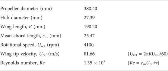
In this investigation, the commercial propeller of the Inspire 2 (1550T Quick Release Propeller, DJI Ltd., China) was used as the standard propeller. For the numerical simulation, the three-dimensional shape of the propeller was reconstructed using laser scanner images. Figure 2 depicts the original propeller as well as the reconstructed shape. Table 1 summarizes all the normal propellers measured parameters. Based on the notional weight (= 3.44 kg) and number of rotors (= 4) of the Inspire 2, the needed lift force of a single propeller for the “hovering condition” was determined by dividing the weight by the number of rotors, yielding a value of around 8.4 N. The rotational speed of the normal and modified propellers utilized in this study was manually adjusted to generate the needed lift force for evaluating flying efficiency and noise level under this hovering state. It is worth noting that the lift forces obtained from all trials in this study are within ±1.6% of the needed lift force. The term “wing length” in this study refers to the half-length of the propeller diameter.

FIGURE 2. Top views of (A) the propeller and (B) the reconstructed three-dimensional model. (C) Reconstructed cross-sections at 0.1R, 0.3R, 0.5R, 0.7R and 0.9R.
2.2 Gurney flap
First, we affixed a simple plate with a height of 1 mm to the trailing edge of the propeller’s lower side, as shown in Figure 3A. According to the results of the noise measurement (described in more detail below), we discovered that propellers with simple plate attachments generate more noise than standard propellers, even when the rotational speed was reduced by more than 500 rpm when hovering. We secondary fabricated the cylinder array attachment with a height of 3 mm based on this finding, as shown in Figures 3B,C. This attachment is made up of a series of cylinders with 1 mm diameters and 1 mm spacing. The experiment’s attachments were fabricated using a 3D printer (Finder, Zhejiang Flashforge3D technology Co., Ltd., China). Note that the size of the diameter of a cylinder was determined taking into account the accuracy of the 3D printer and our previous study (Ikeda et al., 2018) which demonstrated that the denser serrations contribute more to passive boundary layer control. In Chapter 3, the impact of this attachment on aerodynamic and aeroacoustic performance will be discussed in depth.

FIGURE 3. The propellers with (A) the simple plate attachments and (B) the cylinder array attachment. (C) The dimensions of the cylinder array attachment in the case with the height of 3 mm.
2.3 Force and noise measurement
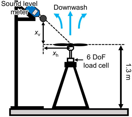
As shown in Figure 4, the propeller models and brushless DC motor (DR55-M, Shinano Kenshi Co., Ltd., Japan) were mounted on a 6 DoF load cell (CFS034CA101U, Leptrino Inc., Japan). For correct propeller balancing, the wing tips on the left and right sides of the propeller models were altered to be horizontal using a laser line generator. In a quiet chamber (18 m × 9 m × 8.4 m), the force and noise of the single propellers were measured. Because the horizontal distances between the wingtips and the building walls are at least 20 times greater than the wing length, the wall effects due to flow interaction are anticipated to be minor under this circumstance. The steady forces in this investigation were determined by measuring the time-varying dynamic forces (600 Hz) operating on the propeller models for 60 s and averaging their results. A precise sound level meter (NL-52, RION Ltd., Japan) with −27 dB sensitivity was placed vertically and horizontally from the propeller hub’s center at distances defined by xv and xh. Note that the noise measurements in the near field at the position of xv and xh = 0.5 m were mainly conducted in this study, but the different positions in the more far field were also evaluated for a comprehensive assessment of the developed propeller (see Section 3.1.3). Noise was measured for 60 s simultaneously with force measurements. In a calm indoor environment, sound pressure levels (SPLs) of the whole data were calculated as follows:
where PA is the instantaneous A-weighted sound pressure with the measuring frequency band ranging from 20 Hz to 20 kHz. P0 expresses the reference sound pressure and it is equal to 20 µPa. N is the number of sampling and the sampling frequency is 48,000 Hz. It should be noted that the noise level in the indoor environment without rotor noise is approximately 30 dB, however over 70 dB was reported with rotor noise in all evaluated models. The figure of merit (FM) of a propeller is defined to measure the efficiency of the tested model:
where Preal expresses the actual power given by the product of the measured torque about the rotational axis and the angular velocity. PRF is the ideal power that means the minimum power for generating the resultant lift force, L which was obtained from the experiment, and can be derived by using the Rankine-Froude momentum theory as bellow (Ellington, 1984).
where ρ is the density of air and A is the area of the actuator disk.
2.4 Numerical simulation
The simulation-based investigation using computational fluid dynamics (CFD) modeling was carried out to evaluate the aerodynamic and aeroacoustic characteristics of the propeller models using the commercial software ANSYS CFX 18.0 (ANSYS Inc., United States). Considering the flow field characteristics in the Reynolds number regime, we first performed Reynolds Averaged Navier-Stokes modeling of the turbulent flow with the SST (Shear Stress Transport) turbulence model to obtain the initial flow field in the unsteady analysis. For incompressible and steady flows, the governing equation is as follows:
where i and j denote suffixes for tensor notation, ui and xi denote the velocity and position vectors, ρ, p and μ denote the fluid density, the pressure and the dynamic viscosity, respectively. The blending strategy using the k-ω and k-ε models is the SST model proposed in the earlier work (Menter et al., 2003). The k-ω model was employed at the surface, whereas the k-ε model can be used for the boundary layer’s edge and its surrounding region. The governing equations are discretized using the finite volume method, and a blending scheme between the first order upwind differencing scheme and the second-order central differencing scheme, known as the high-resolution scheme in this software, was used to solve the advection terms in both equations.
We then performed an unstable analysis with LES modeling using the well-converged steady-state solution as the initial flow field. In this solver, the incompressible LES is achieved by solving the filtered time-dependent Navier-Stokes equations. The low-pass filtering procedure effectively removes eddies with scales smaller than the grid spacing, allowing the large-scale turbulent flow to be solved directly and the filtered small-scale effects to be accounted for in the sub grid-scale (SGS) stress tensor. The wall-adapted local eddy-viscosity (WALE) model proposed in the previous study (Nicoud and Ducros, 1999) was used to compute the SGS viscosity, and this solution is incorporated within ANSYS CFX as an LES WALE model.
As shown in Figure 5, a multi-blocked hybrid grid system with rotating and static domains was used to accurately resolve the turbulent flow and the flow separation around the propeller surfaces. To reduce computational cost, the periodic boundary condition was applied to the boundary planes colored red in both domains. A Frozen Rotor model was used at the boundary faces between the rotating and static domains. The propeller’s surface was set to be the no-slip wall boundary conditions, and 15 prism layers were imposed on the surface, with the first layer having a height of 0.01 mm and a growth rate of 1.04. The static domain’s other boundary planes were set to the opening boundary condition with 0 Pa relative pressure. With this mesh system, the calculations were done up to 3.5 rotations from the start of the unsteady analysis for the normal and plate models, and 2.5 rotations for the cylinder model, due to the convergence of the flow field and our restricted computer resources. The operating conditions of the tested propeller models and the sensitivity analysis on grid points are summarized in supplementary material (see Supplementary Tables S1, S2). Each model’s rotating speed was set to the values acquired during the experiment (4100, 3650 and 3900 rpm for normal, plate and cylinder models, respectively).

FIGURE 5. Mesh systems for CFD simulations. (A) Computational domain around the normal propeller model and (B) rotating domain (C) The surface meshes of the propeller.
3 Results and discussions
3.1 Experimental results
3.1.1 Aerodynamic performance and noise level of normal propeller
The experimental results revealed that the reference (Normal) propeller generated the lift required for hovering flight at a rotation speed of 4100 rpm and an FM of approximately 0.66. At this rotational speed, the noise level at the position of xv and xh = 0.5 m was 70.5 dB, showing that the propeller emits exceptionally loud noise. Because of the two blades, the blade pass frequency should be double the rotational frequency (= 136.6 Hz). This blade pass frequency dominates the entire drone noise, as high noise levels occur even as its overtones. In a prior study, the noise level at the blade pass frequency was reduced by lowering the rotating speed by inserting a plate at the trailing edge that increased the wing area (Noda et al., 2018). However, the change in the wing planform resulted in a drop in aerodynamic performance, such as the lift to drag ratio. Multi-rotor drones employ a wide range of propellers. Serrated features in the leading edge of some propellers have been demonstrated to be effective at reducing noise levels (Wei et al., 2020). However, many propellers are intended to keep the flow on the wing surface smooth and to prevent flow separation, so the importance of the leading-edge serration in controlling the boundary layer (Ikeda et al., 2018) may be restricted. In this study, we aimed to reduce noise by using trailing-edge serrations, with the goal of lowering the reliance on propeller geometry and offering a simple structure for a range of propellers.
3.1.2 Effect of Gurney flap on the aeroacoustics of drone propeller
Because of the improvement of the lift coefficients, the trailing-edge attachments are found to reduce the rotation speed to provide the same amount of lift. Figure 6A summarizes the effect of the trailing-edge attachment on the SPL and FM. In comparison to a standard propeller, the simple plate attachment with a trailing-edge height of 1 mm (see Figure 3A) results in a minor drop in FM but around 6 dB louder noise. In contrast, by replacing the plate with a series of cylinders and gaps (see Figure 3B), the noise gradually reduces with increasing height, with the exception of the 8 mm case. The FMs drop in all cases, and the 8 mm attachment follows the same pattern as the plate attachment, with a decrease in FM and an increase in noise level. The frequency of blade passes decreases as the height of the serrated attachment increases (Figure 6B). In the 6 and 8 mm height examples, there is no change in the rotating speed at which the needed lift force is generated, showing that the reduction in rotational speed has converged around 6 mm. Because the noise increases dramatically when the height is increased from 6 mm to 8 mm, there is a limit to the height at which the attachment pressure fluctuations can be reduced.
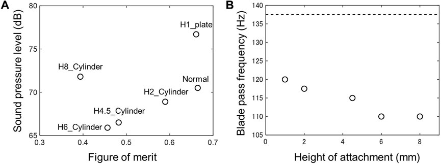
FIGURE 6. (A) Effect of the trailing-edge attachment on the FM, the SPL and (B) the blade pass frequency from experimental results. Dashed line represents the case of the normal propeller.
3.1.3 Parametric study
In contrast to previous studies on the Gurney flap effect for two-dimensional and fixed wing models (Storms and Jang, 1994; Li et al., 2002; Wang et al., 2008), inflow velocities vary at each spanwise point due to wing rotation. As a result, trailing-edge attachments may effect noise in a different way than two-dimensional examples. We conducted a parametric research with a particular emphasis on the spanwise position of serrated attachments with heights of 2 and 3 mm. The spanwise position of the attachment was defined by the clearance length L (Figure 7A). Figure 7B depicts the effect of the attachment’s tip position from the wing tip on the SPL and FM. The FMs approach the normal case as the clearance length L is increased, demonstrating that the trailing-edge attachment has no effect at the low inflow velocities around the wing root. Noise levels are reduced in instances with clearance lengths between 3 and 9 cm; however, noise levels in cases between these lengths are about similar to or greater than in the standard case. The mechanism underlying the difference in noise levels at different spanwise points is unknown, however it is most likely related to the region of high pressure and turbulence formation. According to the findings, the spanwise area from 3 to 5 cm from the wing tip is the critical location where noise can be minimized by attaching a serrated Gurney flap. Because FMs drop as clearance length decreases, we used a partial attachment mounted from L = 3–6 cm from the wing tip. Figure 8A summarizes the effects of the height and gap for the partial attachment on the FM and SPL. When the cylinders are high in height, the noise level decreases, but the efficiency decreases as well. Both FM and SPL are roughly equal in the case with the 2 mm gap (H3_G2), illustrating the limited effect of a Gurney flap. If a large drop in flight efficiency is permitted, it is possible to minimize the noise level. In this analysis, the partial attachment case with a height of 3 mm and a gap of 1 mm (H3_G1) is found to be the optimal design in the range of this investigation, assuming that the drop in flight efficiency should be kept within 10%.
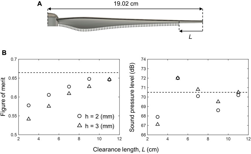
FIGURE 7. Experimental results. (A) Definition of the clearance length, L. (B) Effect of the tip position of the attachment from the wing tip on the FM and the SPL. Dashed lines represent the case of the normal propeller.
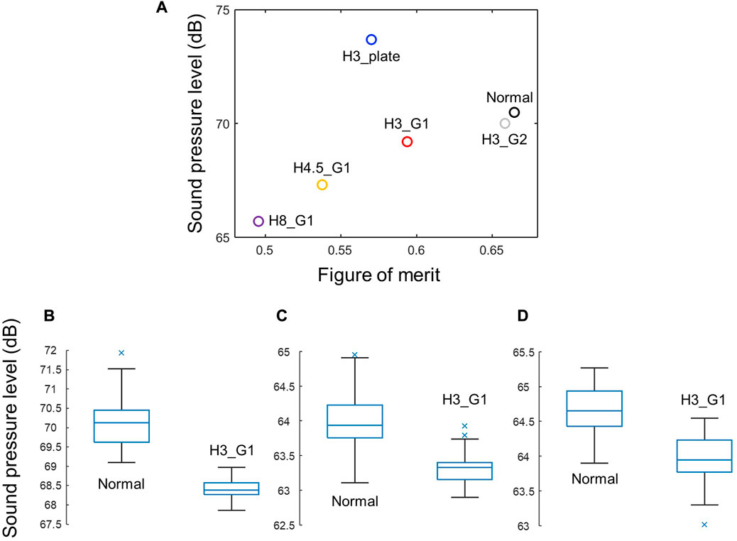
FIGURE 8. Experimental results. (A) Effects of the height and the gap for the partial attachment on the FM and the SPL Sound pressure level of the normal and the partial cylinder attachment (H3_G1) models at the position of (B) xv and xh = 0.5 m, (C) xv = 0.5 m and xh = 1.0 m and (D) xv and xh = 1.0 m.
The rotor noise in the near and far fields has different characteristics. Therefore, the blade passing frequency acts differently for modulating the intensity of the broadband noise depending on the noise measurement location (Baars et al., 2021). In addition, flow recirculation can affect the noise measurements in indoor experiments (Whelchel et al., 2020). Therefore, in order to provide a comprehensive evaluation of this partial cylinder attachment model (H3_G1), we have conducted the noise measurement at the several locations and the statistical analysis to show the validity of the noise reduction of this model. The data (60 s) was divided into a series of 1 s data without overlap, and the sound pressure level at each window has been calculated based on Eq. 1. The standard deviations of the SPLs are 0.2–0.7 dB (see Supplementary Table S3), which are close to the level of uncertainty (1–1.5 dB) in the literature (Bendat and Piersol 2011). The SPLs of each propeller has been compared by analysis of variance (ANOVA), and the statistical significance has been estimated by the p-value that is the probability that the null hypothesis of no difference between the mean values is true. The results showed that although the reduction in noise levels in the far field was smaller than in the near field, the noise levels of the developed propeller decreased at all locations. The p-values were much lower than 0.1% (ranged from 2.6 × 10−38 to 5.0 × 10⁻¹⁸); therefore, we concluded that the differences of sound pressure levels are statistically significant (Figures 8B–D). In the future study, the influence of the diameter, gap, and shape of the cross sections will be examined.
3.1.4 Frequency spectrum
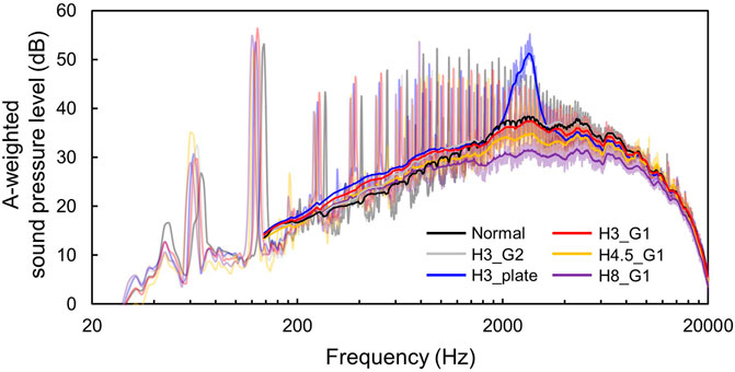
We did a spectrum analysis of the measured noise to analyze the changes in noise characteristics between the partial plate and cylinder attachments in detail (Figure 9). In comparison to the standard one, trailing-edge attachments can reduce rotational speed, as shown at blade pass frequencies ranging from 120 to 138 Hz. Noise levels grow from 200 to 800 Hz, but they decrease over 4000 Hz in all models. The propeller with the plate attachment (H3_plate) significantly raises the noise level, particularly around 2700 Hz, owing to flow separations and periodic vortex generation by the plate. A similar peak in sound pressure level at specific frequencies was observed in the simultaneous measurement of time-resolved particle image velocimetry and sound measurements for a NACA0015 airfoil with a (simple plate, no serrated structure) Gurney flap with a height of 6% of the chord length, indicating to be consistent with the vortex shedding frequency (Zhang et al., 2018). As a result, the overall SPL is more than 3 dB higher than the normal value. The propeller with the cylinder attachment is found to inhibit such an increase in noise level, and the overall SPL is reduced by more than 1 dB for all models except for the 2 mm gap model (H3_G2), compared to the standard one. It has been proposed that the discomfort induced by drone noise is due to its unique acoustic properties, such as pure tones and high-frequency broadband noise (Schäffer et al., 2021). Gurney flaps with serrated structures can avoid the peaks in SPLs found in plain plate constructions and can reduce overall sound pressure level. The effectiveness of noise reduction in the broadband area of high frequencies could make it more user-friendly in urban environments.
3.2 Computational results
3.2.1 Aerodynamic force and surface pressure
The time transient analysis with the LES WALE model was undertaken to investigate the mechanism of noise reduction. Table 2 shows the unsteady analysis’s resultant mean forces during the last half revolution. The mean lift forces obtained here are slightly lower for all models than the experimental values (≒4.2 N), which could be due to inaccuracies in the computational model design. However, the highest inaccuracy compared to the experimental data is approximately 3%, and the differences in simulated lift forces between the normal model and the other models are within 1.5%; hence, a comparison within the numerical results is reasonable.
There are no significant differences in mean lift forces, however mean drag forces rose by 25% for the plate model and 14% for the cylinder model as compared to the normal model. As a result, the increase in drag on the attachment structures exceeds the decrease in drag with decreasing rotational speed. Figure 10 depicts the time-averaged pressure patterns on the surfaces. In the plate and cylinder models, there are no significant variations in the negative pressure distributions on the top surfaces, but the substantial positive pressure distributions on the lower surfaces occur near the attachments. The positive pressure near the attachments increases toward the wing tips, and the plate model has the highest positive pressure values (Figure 10B). The element-averaged pressures at the final time step were computed to be −869, −858, and −872 Pa on the upper surfaces, and 125, 163, and 144 Pa on the lower surface for the normal, plate, and cylinder models, respectively. The results show that the decrease in lift with decreasing rotational speed is compensated for in the attachment models by an increase in positive pressure on the lower surfaces, indicating that the effects of Gurney flaps as a high lift device for a fixed wing are also applicable to rotational wings. A positive pressure is generated on the inside of the attachment surfaces (see box on the right-hand side of Figure 10A) where the inflow velocity into the wing is received, and a negative pressure is detected on the outside, resulting in substantial drag forces.
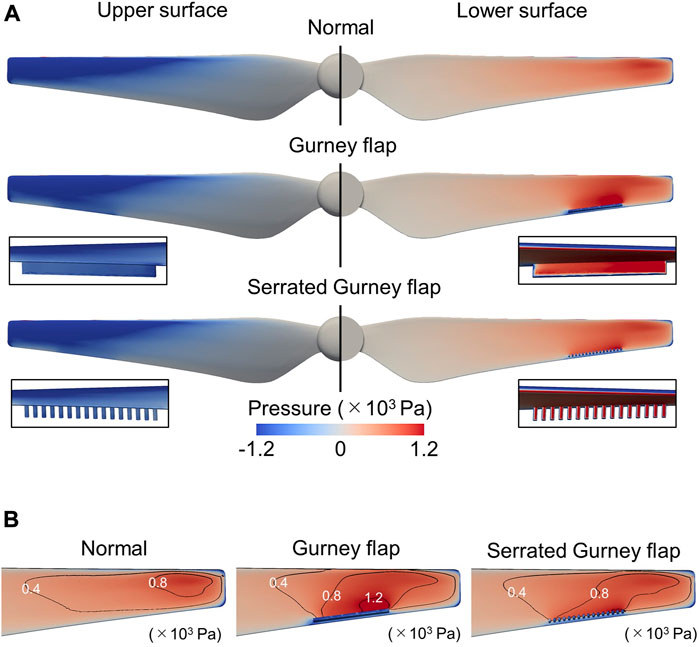
FIGURE 10. Computational results. (A) Pressure distribution of three tested models. (B) Enlarged view near the attachments with the pressure contours on the lower surface.
Figure 11A compares the pressure oscillations of a standard propeller, a propeller with a plate attachment, and a propeller with a cylinder attachment. For a standard propeller, the pressure oscillation is greatest toward the distal area, slightly beyond the wing tip, where turbulence, or noise, can be generated to a substantial extent. By reducing the rotating speed, both attachment styles slightly decrease such pressure oscillation on the upper surface. Large pressure oscillations can be detected on the lower surfaces of the plate and cylinder models, notably at the plate edge on the blade tip side, which may be owing to strong vortices generated by the plate edge.
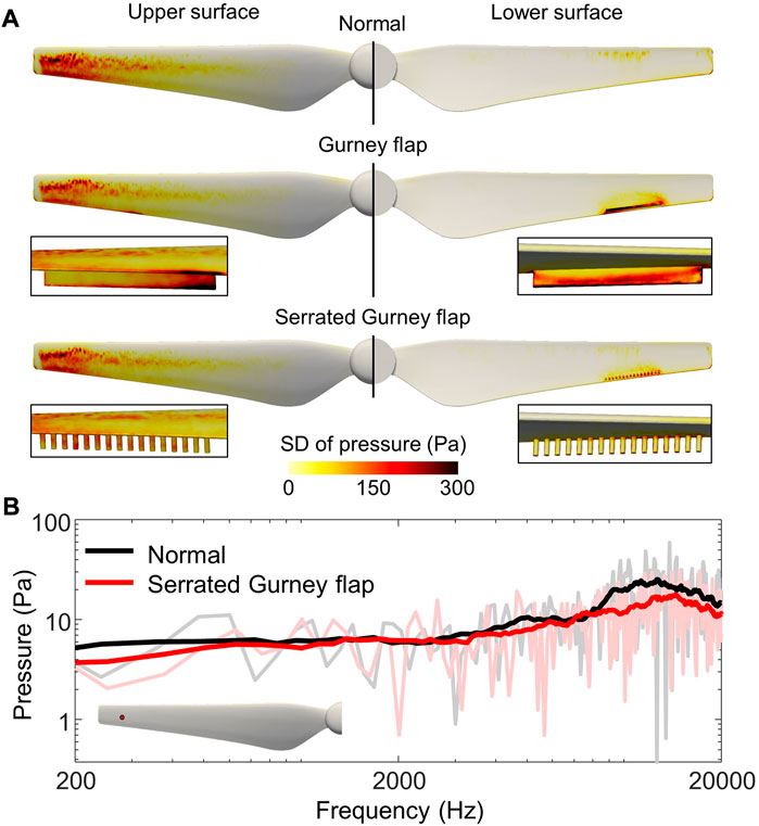
FIGURE 11. Computational results. (A) Standard deviation of pressure on surfaces. (B) Frequency spectrum of the pressure oscillation at the mid-chord of the upper surface of propellers (red circle in the inset).
We have further analyzed the frequency spectrum of the pressure on the upper surface at mid-chord of propellers (Figure 11B). The comparison of the frequency spectrum suggests that the reduction of the pressure oscillation over the upper surface is mainly accounted for by the reduction of the pressure oscillation at the frequencies higher than 2,000 Hz. The frequency range for the pressure reduction is similar to those of SPL (Figure 9) by the attachment (H3_G1). From the coincidence between experimental and computational results, the serrated Gurney flap is thought to reduce the noise by the reduction of the pressure oscillation on the upper surface in comparison with the normal propeller.
3.2.2 Vortex and pressure fields near surface
Figure 12 compares the iso-surface of the Q-criterion around the normal, plate, and cylinder models. Numerous fine vortices shed from the upper surface and trailing edge of all models, and significant wingtip vortices occur at the wingtip. Strong vortices are shedding from the plate surfaces and edges in the plate model, and this impacts the bottom surface, which has no vortices in the normal model. In contrast, even surrounding the attachment, the cylinder model did not produce the characteristic strong vortex formations. Although there is an area of fine vortices spreading on the bottom surface, the vortex structure is nearly identical to that of the normal model. It can be seen that the wingtip vortices retain roughly the same strength in all models, and the vortices shedding from the trailing edge between the attachment and the wingtip are also roughly equivalent, indicating that the vortex interaction between the wingtip vortices and the attachment vortices can be avoided. The results showed that attaching the trailing-edge structure at a distance from the wingtip improves its aerodynamic and aeroacoustic performance. A separation from the wingtip is considered necessary in the serrated Gurney flap to minimize interfering with this wingtip vortex. Figures 13A–C show the pressure distributions and streamlines on the cross section at 0.76R of each wing model. In the wake of the Gurney flap, both attachment models show a high negative pressure area (Figures 13B,C) caused by two counter rotating alternatively shed vortices.
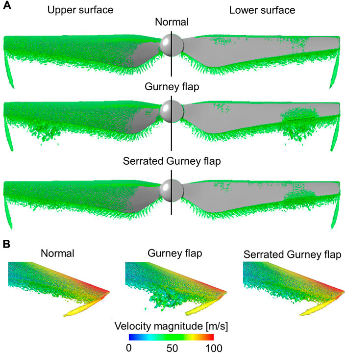
FIGURE 12. Computational results. Iso-surface of Q-criterion at 2.0×10⁷ (1/s2) from multiple viewing angles. (A) Top and bottom views. (B) Oblique view.
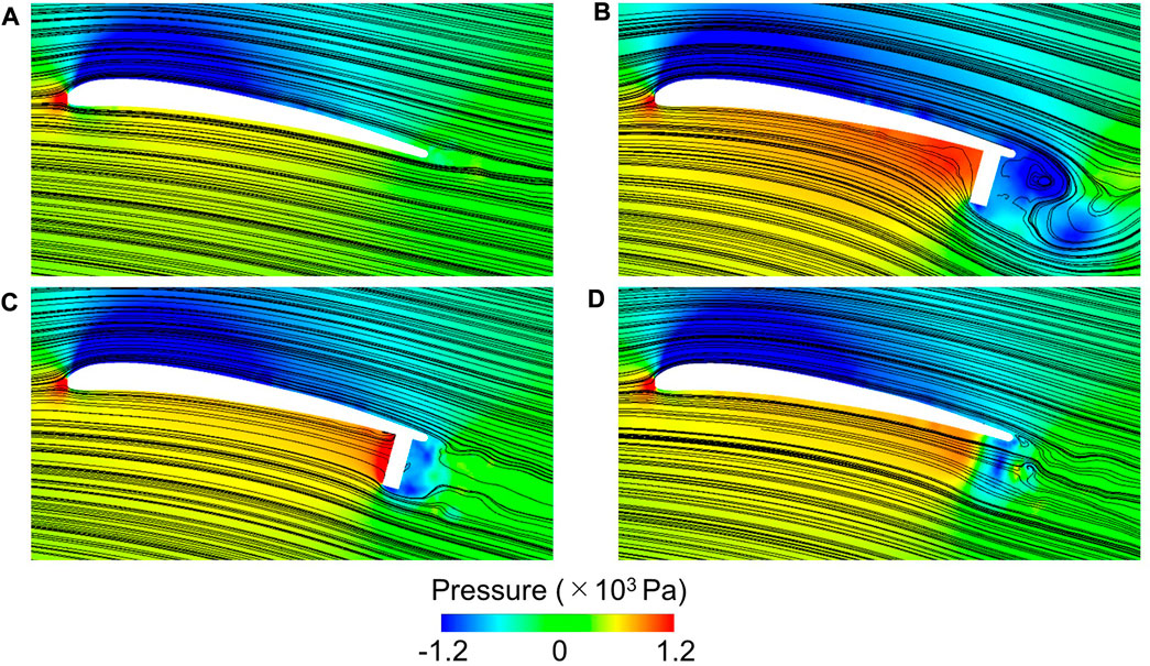
FIGURE 13. Computational results. Pressure distribution and streamline on the cross section at 0.76R for (A) the normal, (B) the plate and (C) the cylinder models. The visualized spanwise position is approximately equal to the center of each attachment. (D) The visualization in the gap at 0.766R between the cylinders.
3.2.3 Aerodynamic mechanism of noise reduction with serrated Gurney flap
Based on the simulated flow fields, we can see how the serrated Gurney flap improves the aeroacoustic performance of the propeller. Due to the vortices formed by the plate edges (Figure 13B), large pressure oscillations are detected on the plate surface (Figure 11). Many numerical and experimental studies have observed the two counter rotating vortices in the wake of the Gurney flap (Jeffrey and Zhang, 2000; Jain et al., 2015; He et al., 2016), with the intensity of these vortices increasing with rising turbulence intensity as the height of the Gurney flap increases. The serrated structure of the attachment appears to operate efficiently in inhibiting the generation of the strong vortices observed in the plate model (Figures 13B–D), resulting in a smaller pressure oscillation than the model with plate (Figure 11A) as well as the normal plate at the frequencies higher than 2,000 Hz (Figure 11B). Although the reduction of negative pressure behind the cylinder weakens the effects of the Gurney flap, such as the decrease in pressure over the suction surface and the delay in flow separation due to the increase in velocity on the upper surface (Xie et al., 2016), the serration structure in the Gurney flap can produce a reduction in speed due to the increase in positive pressure at the lower surface of the blade without significantly impacting the velocity fluctuation in the wake, resulting in noise reduction. Therefore, the serrated structure at the trailing edge is shown to boost performance by suppressing turbulence formation as well as large-scale flow separations at the trailing-edge plate, in a way similar to noise suppression by the owl feather’s leading-edge serrations (Rao et al., 2017; Wang L. et al., 2021). The propeller utilized in this study has a Mach number of approximately 0.24, which is a low Mach number flow that does not necessitate the consideration of compressibility. As a result, the sound is affected by the pressure fluctuations.
4 Conclusion
In this study, we used the serrated Gurney flap to construct a low-noise propeller. Experimental parameter sweeps and CFD calculations were used to characterize the propeller’s aerodynamic and aeroacoustics performance with the trailing-edge attachment. We experimentally established the importance of attachment position and height in reducing noise while maintaining aerodynamic performance. Simulations also demonstrated that noise reduction is accomplished by suppressing the separation of large-scale vortices. While the attachment’s design, such as the diameters, gaps, and forms, needs to be optimized, the microstructure at the trailing edge has a tremendous potential to reduce the noise level of drone propellers. Furthermore, with the development of aerial acoustic surveillance with a drone, it is expected that a wide range of sounds can be detected, and it will be necessary to develop various propeller models equipped with different noise characteristics by using a simple attachment, as we proposed in this study.
Data availability statement
The raw data supporting the conclusions of this article will be made available by the authors, without undue reservation.
Author contributions
RN and TN conceived the study. RN, TI, and TN performed the experiments and analysed the data. RN performed the numerical simulation. All authors wrote and contributed to the final version of the manuscript and approved the submission.
Funding
This work was supported by JSPS KAKENHI Grant Number 19H00750 and was partly supported by JSPS KAKENHI Grant Number JP20H05752.
Acknowledgments
The authors thank Takuya Soga for help in constructing the experimental setup.
Conflict of interest
Author TI is employed by Teral Inc.
The remaining authors declare that the research was conducted in the absence of any commercial or financial relationships that could be construed as a potential conflict of interest.
Publisher’s note
All claims expressed in this article are solely those of the authors and do not necessarily represent those of their affiliated organizations, or those of the publisher, the editors and the reviewers. Any product that may be evaluated in this article, or claim that may be made by its manufacturer, is not guaranteed or endorsed by the publisher.
Supplementary material
The Supplementary Material for this article can be found online at: https://www.frontiersin.org/articles/10.3389/fpace.2022.1004828/full#supplementary-material
References
Baars, W. J., Bullard, L., and Mohamed, A. (2021). “Quantifying modulation in the acoustic field of a small-scale rotor using bispectral analysis,” in AIAA paper No. AIAA 2021-0713. doi:10.2514/6.2021-0713
Bendat, J. S., and Piersol, A. G. (2011). Random data: Analysis and measurement procedures. New York: John Wiley & Sons.
Clark, C. J., and Jaworski, J. W. (2020). Introduction to the symposium: Bio-inspiration of quiet flight of owls and other flying animals: Recent advances and unanswered questions. Integr. Comp. Biol. 60, 1025–1035. doi:10.1093/icb/icaa128
Curle, N., and Lighthill, M. J. (1955). The influence of solid boundaries upon aerodynamic sound. Proc. R. Soc. Lond. A Math. Phys. Sci. 231, 505–514. doi:10.1098/rspa.1955.0191
Ellington, C. P. (1984). The aerodynamics of hovering insect flight. ⅴ. A Vortex Theory. phil. Trans. R. Soc. lond. B 305, 115–144. doi:10.1098/rstb.1984.0053
Graham, R. R. (1934). The silent flight of owls. J. R. Aeronaut. Soc. 38, 837–843. doi:10.1017/S0368393100109915
He, X., Wang, J. J., Yang, M. Q., Ma, D. L., Yan, C., and Liu, P. Q. (2016). Numerical simulation of Gurney flap on SFYT15thick airfoil. Theor. Appl. Mech. Lett. 6, 286–292. doi:10.1016/j.taml.2016.09.002
Ikeda, T., Ueda, T., Nakata, T., Noda, R. D., Tanaka, H., Fujii, T., et al. (2018). Morphology effects of leading-edge serrations on aerodynamic force production: An integrated study using PIV and force measurements. J. Bionic Eng. 15, 661–672. doi:10.1007/s42235-018-0054-4
Ito, S. (2009). Aerodynamic influence of leading-edge serrations on an airfoil in a low Reynolds number - a study of an owl wing with leading edge serrations -. J. Biomech. Sci. Eng. 4, 117–123. doi:10.1299/jbse.4.117
Jain, S., Sitaram, N., and Krishnaswamy, S. (2015). Computational investigations on the effects of Gurney flap on airfoil aerodynamics. Int. Sch. Res. Not., 1–11. doi:10.1155/2015/402358
Jeffrey, D. R., Zhang, X., and Hurst, D. W. (2000). Aerodynamics of Gurney flaps on a single-element high-lift wing. J. Aircr. 37, 295–301. doi:10.2514/2.2593
Li, Y., Wang, J., and Zhang, P. (2002). Effects of Gurney flaps on a NACA0012 airfoil. Flow. Turbul. Combust. 68, 27–39. doi:10.1023/A:1015679408150
Liebeck, R. H. (1978). Design of subsonic airfoils for high lift. J. Aircr. 15, 547–561. doi:10.2514/3.58406
Lighthill, M. J. (1952). On sound generated aerodynamically I. General theory. Proc. R. Soc. Lond. A Math. Phys. Sci. 211, 564–587. doi:10.1098/rspa.1952.0060
Menter, F. R., Kuntz, M., and Langtry, R. (2003). Ten years of industrial experience with the SST turbulence model. Heat. Mass Transf. 4, 625–632.
Nicoud, F., and Ducros, F. (1999). Subgrid-scale stress modelling based on the square of the velocity gradient tensor. Flow. Turbul. Combust. 62, 183–200. doi:10.1023/A:1009995426001
Noda, R., Nakata, T., Ikeda, T., Chen, D., Yoshinaga, Y., Ishibashi, K., et al. (2018). Development of bio-inspired low-noise propeller for a drone. J. Robot. Mechatron. 30, 337–343. doi:10.20965/jrm.2018.p0337
Nonami, K. (2016). Drone technology, cutting-edge drone business, and future prospects. J. Robot. Mechatron. 28, 262–272. doi:10.20965/jrm.2016.p0262
Rao, C., Ikeda, T., Nakata, T., and Liu, H. (2017). Owl-inspired leading-edge serrations play a crucial role in aerodynamic force production and sound suppression. Bioinspir. Biomim. 12, 046008. doi:10.1088/1748-3190/aa7013
Rizzi, S. A., Huff, D. L., Boyd, D. D., Bent, P., Henderson, B. S., Pascioni, K. A., et al. (2020). NASA/TP–2020-50074337. Hampton, VA, USA: NASA.Urban air mobility noise: Current practice, gaps, and recommendations
Schäffer, B., Pieren, R., Heutschi, K., Wunderli, J. M., and Becker, S. (2021). Drone noise emission characteristics and noise effects on humans-A systematic review. Int. J. Environ. Res. Public Health 18, 5940. doi:10.3390/ijerph18115940
Storms, B. L., and Jang, C. S. (1994). Lift enhancement of an airfoil using a Gurney flap and vortex generators. J. Aircr. 31, 542–547. doi:10.2514/3.46528
Torija, A. J., and Clark, C. (2021). A psychoacoustic approach to building knowledge about human response to noise of unmanned aerial vehicles. Int. J. Environ. Res. Public Health 18, 682. doi:10.3390/ijerph18020682
Wagner, H., Weger, M., Klaas, M., and Schröder, W. (2017). Features of owl wings that promote silent flight. Interface Focus 7, 20160078. doi:10.1098/rsfs.2016.0078
Wang, J., Ishibashi, K., Ikeda, T., Fujii, T., Nakata, T., and Liu, H. (2022). Morphological effects of leading-edge serrations on the acoustic signatures of mixed flow fan. Phys. Fluids (1994). 34, 041909. doi:10.1063/5.0088851
Wang, J., Ishibashi, K., Joto, M., Ikeda, T., Fujii, T., Nakata, T., et al. (2021a). Aeroacoustic characteristics of owl-inspired blade designs in a mixed flow fan: Effects of leading- and trailing-edge serrations. Bioinspir. Biomim. 16, 066003. doi:10.1088/1748-3190/ac1309
Wang, J. J., Li, Y. C., and Choi, K.-S. (2008). Gurney flap-lift enhancement, mechanisms and applications. Prog. Aerosp. Sciences 44, 22–47. doi:10.1016/j.paerosci.2007.10.001
Wang, L., Liu, X., and Li, D. (2021b). Noise reduction mechanism of airfoils with leading-edge serrations and surface ridges inspired by owl wings. Phys. Fluids (1994). 33, 015123. doi:10.1063/5.0035544
Wei, Y., Xu, F., Bian, S., and Kong, D. (2020). Noise reduction of UAV using biomimetic propellers with varied morphologies leading-edge serration. J. Bionic Eng. 17, 767–779.
Whelchel, J., Alexander, W. N., and Intaratep, N. (2020) Propeller noise in confined anechoic and open environments, In AIAA Paper No. AIAA 2020-1253: doi:10.2514/6.2020-1252
Xie, Y. H., Jiang, W., Lu, K., and Zhang, D. (2016). Numerical investigation into energy extraction of flapping airfoil with Gurney flaps. Energy 109, 694–702. doi:10.1016/j.energy.2016.05.039
Keywords: Gurney flap, serration, propeller, noise, drone
Citation: Noda R, Ikeda T, Nakata T and Liu H (2022) Characterization of the low-noise drone propeller with serrated Gurney flap. Front. Aerosp. Eng. 1:1004828. doi: 10.3389/fpace.2022.1004828
Received: 27 July 2022; Accepted: 30 September 2022;
Published: 14 October 2022.
Edited by:
T. H. New, Nanyang Technological University, SingaporeReviewed by:
Nick Zang, University of Bristol, United KingdomPatrick N. Okolo, Oxford Brookes University, United Kingdom
Copyright © 2022 Noda, Ikeda, Nakata and Liu. This is an open-access article distributed under the terms of the Creative Commons Attribution License (CC BY). The use, distribution or reproduction in other forums is permitted, provided the original author(s) and the copyright owner(s) are credited and that the original publication in this journal is cited, in accordance with accepted academic practice. No use, distribution or reproduction is permitted which does not comply with these terms.
*Correspondence: Ryusuke Noda, bm9kYXJ5c2tAc3RmLnRldS5hYy5qcA==; Toshiyuki Nakata, dG5ha2F0YUBjaGliYS11Lmpw
 Ryusuke Noda
 Teruaki Ikeda
 Toshiyuki Nakata
 Hao Liu
