 Jacek Wojtanowski
94% of researchers rate our articles as excellent or good
Learn more about the work of our research integrity team to safeguard the quality of each article we publish.
Find out more
ORIGINAL RESEARCH article
Adv. Opt. Technol., 21 March 2025
Sec. Optical Manufacturing and Design
Volume 14 - 2025 | https://doi.org/10.3389/aot.2025.1568420
Introduction: Apart from discussing general issues related to the application of freeform telescopes, this work presents a design of ultra-compact high-resolution freeform telescope dedicated to CubeSat application associated with Earth surface imaging from Low Earth Orbit (LEO), providing high resolution (Ground Sampling Distance, GSD <5 m) and 20 km width of the observed Earth strip.
Methods: The telescope was designed in a three-mirror off-axis configuration according to the <0.5U volume constraint. Freeform surfaces were described by shifted polynomial equations. In order to prevent optimization falling into numerous local minima of multi-variate merit function, the new design strategy was proposed. The optical design commercial software was supplemented by add-on responsible for dynamically modifying the set of variables in the loop during the optimization process.
Results: The designed 250 mm f/4.9 telescope meets the assumed operational and volumetric criteria. It fits into the volume of 5 × 10 × 10 cm cuboid. It is diffraction limited across the whole (3o) field of view.
Discussion: Freeform optics design technology was successfully applied to design a miniature space telescope. The proposed design algorithm proved to be computationally efficient. It enabled to obtain the excellent imaging of the designed telescope, which from mathematical perspective becomes a challenging multi-variable optimization task, unattainable with the standard optimization procedures included in the commercial optical design software.
The current development of satellite technology, for more than 10 years time, is largely dominated by small satellites called nanosatellites or CubeSats (deLoughery et al., 2024; Shiroma et al., 2011), with a cubic or cuboid shape, in many cases similar in size to a thermos for tea. Nanosatellites are dedicated especially to operating in low Earth orbit (400–650 km above the Earth’s surface), usually moving at a speed of about 8 km/s, which at this altitude corresponds to a 90-min orbit (14–15 orbits of our planet per day). Their design has been standardized and the size is defined by a multiple of a unit cube with dimensions of 10 × 10 × 10 cm referred to as 1U (Figure 1). The weight of nanosatellites corresponds to their small dimensions and is usually in the range of 1.33 kg–30 kg, which in comparison with “classic” satellites makes them clearly miniature structures.
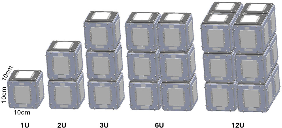
Figure 1. CubeSats type series concept visualization.
Standardization guarantees the possibility of constructing nanosatellites from COTS and quickly available base modules, which significantly reduces production time and costs, and consequently further accelerates the development of this technology. In this way, space research is no longer reserved exclusively for high-budget, multi-million research and military projects. With funds starting from a few dozen thousand euros, it is possible to send a small, not very complicated research satellite into Earth orbit.
In the context of nanosatellite equipment, it is important to require that no instrument (payload) located on the nanosatellite protrudes beyond the external outline of the nanosatellite structure, i.e., fits inside the aforementioned cubic or cuboid structure (this property is the basic factor distinguishing nanosatellites from equally small, but not so standardized, microsatellites). This also results from unified (and therefore significantly cheaper) procedures for launching nanosatellites into orbit. However, such a requirement causes an obvious need to minimize the dimensions (and also the weight) of instruments dedicated to use on nanosatellites.
Despite the requirements for reduced dimensions and mass, expectations regarding the quality of Earth’s surface images obtained from miniature satellites remain consistently high or even become higher, as they result from similar or more demanding operational needs. Initially, it might seem that the capabilities of modern technology in the production of miniature precision optical systems, as well as imaging sensors based on increasingly smaller pixels, provide the potential for building small telescopes that provide no worse resolution compared to larger telescopes based on older solutions. There is a certain paradox here. The size of Point Spread Function (PSF) results exclusively from f/# of the telescope’s optical system (ratio of its focal length f to entrance pupil diameter D). Let us recall that for an optical system with a circular pupil, the PSF takes the form of an Airy spot with a diameter of 2.44λ(f/#). For this reason, scaling the optical system to smaller dimensions (and thus maintaining f/# unchanged) does not increase the PSF size, and thus seemingly also does not deteriorate the image quality. Unfortunately, it should be remembered that due to the reduction of the system focal length (which is the case when scaling), the image size is also scaled down. By recalling the fundamental mechanism of incoherent imaging, as the convolution of the PSF function with an ideal image, we come to the crux. Namely, although the PSF size remains unchanged, the convolution of this PSF with a geometrically reduced image produces a net effect showing the deterioration of the image quality. We therefore conclude that rescaling the optical system (reducing its dimensions), even while maintaining f/#, negatively affects the image quality. A similar conclusion can be reached based solely on the Rayleigh resolution criterion, which defines the maximum resolution of the telescope by means of the minimum angular size in the object that the telescope is able to transfer to the image. Let us remind that this angle depends on the telescope wavelength-to-diameter ratio (1.22λ/D), and when scaling the telescope to a smaller size, this diameter is reduced. As a result, the telescope resolution also decreases. Therefore, two mutually opposing issues can be identified - on the one hand, the pursuit of miniaturization of satellite optics, and on the other hand - the laws of optics that prevent the indiscriminate reduction of optical systems if the priority is to ensure sufficiently high image quality. When referring to telescopic structures dedicated to applications on nanosatellites, one should therefore be guided by a compromise between size and image quality. Achieving this compromise can be difficult, however. This is due to the fact that high image quality requires effective aberration correction, which in turn can result in a large number of required optical elements. However, this is associated with the increasing size of the optical system. In an effort to maintain a compact optical system by eliminating the need for many optical elements, classic spherical elements are being replaced with more sophisticated aspherical elements, or even freeform elements.
Traditional axisymmetric designs of reflecting telescopes, i.e., those based on spherical or aspherical mirrors, generate two fundamental limitations in terms of the achievable imaging quality and the dimensions of the structure: central obscuration and limited number of degrees of freedom. Central obscuration, which corresponds to the partial blocking of light reaching the primary mirror by the secondary mirror or other components in the optical path (Bentley and Olson, 2013a), such as those associated with the secondary mirror mount (so-called “spider”). This situation occurs in all axisymmetric reflecting telescopes. This leads to a decrease in image quality and a decrease in its resolution due to the phenomenon of additional diffraction on the central obscuring components. In order to eliminate the central obscuring effect, it is also possible to design so-called off-axis structures based on axisymmetric elements, in which the secondary mirror does not occur at all or is located outside the outline of the primary mirror (Bentley and Olson, 2013b; Fischer et al., 2008). The disadvantage of such solutions, however, is the need to produce large-sized optical elements, from which the off-axis sector is then cut out, and the remainder contributes to a production waste. Additionally, due to the work “away from the optical axis”, the requirements for mechanical precision of such a solution increase - minimal adjustment errors lead to significant optical aberrations and image deterioration. Nevertheless, in satellite imaging techniques, off-axis structures (without central obscuration) play a significant role. However, these are not telescopes based on a single mirror, but three-mirror ones. In most cases, these are aplanatic, anastigmatic and zero-field-curvature systems, most often called TMA (Three Mirror Anastigmat). There are many configurations of TMA telescopes, differing in the distribution of optical power between the three component mirrors (examples shown in Figure 2).
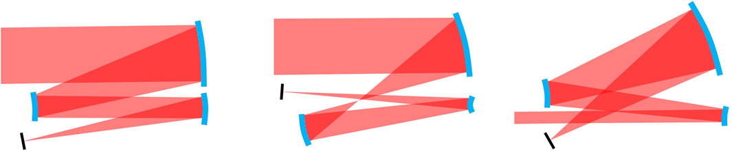
Figure 2. Examples of TMA telescope configurations (from left: +– +, ++–, – –+).
Most classic TMA telescopes are based on axisymmetric elements - aspherical mirrors (paraboloid, hyperboloid or ellipsoidal), by cutting out an off-axis section from them. The use of freeform mirrors in this place allows for larger fields of view and lower f/# of telescope, while maintaining the current or even reduced dimensions.
In addition to the above discussed central obscuration, the second effect limiting the high-quality imaging in a wide field of view, is the rotational symmetry of conventional optical elements, which is formally associated with a small number of so-called degrees of freedom, i.e., parameters necessary to define the shape of their surface. In optical design methods, there is a simple rule that the more degrees of freedom a designer has at their disposal, the greater the possibilities of achieving a system free of aberrations (diffraction limited system). Therefore, when designing a system based on elements (surfaces) with a small number of degrees of freedom, achieving a greater number of degrees of freedom is possible only by using many such components. For this reason, traditional telescope designs often result in solutions with large dimensions and significant mass. In many applications, this is not of great importance, but in the case of telescopes dedicated to work on nanosatellites, this issue is crucial.
The above limitations associated with a small number of degrees of freedom can be largely eliminated by using freeform surfaces (Fang et al., 2013; Rolland et al., 2021), i.e., surfaces with shape not limited by any symmetry constraints. Such a surface can have an infinite number of degrees of freedom (Broemel et al., 2017a), and above all it does not have to have any symmetry constraints. As a result, firstly it is possible to get rid of central obscuration by designing telescopes in an off-axis configuration, and secondly to achieve excellent aberration correction thanks to a large number of degrees of freedom. Due to the lack of a fixed axis of symmetry, it is possible to obtain diverse and complex shapes, which traditional surfaces with an imposed axis of symmetry do not allow to obtain. The complete freedom of shape defines a breakthrough in the field of possibilities of optical systems, breaking the classical paradigms of rotational symmetry, which lead to numerous imaging and non-imaging applications (Broemel et al., 2017a; Broemel et al., 2017b; Geyl et al., 2019; Liu et al., 2021; Peschel et al., 2017; Talpur and Herkommer, 2016; Zhang et al., 2021). These paradigms have been functioning for centuries due to the possibilities of producing only surfaces with rotational symmetry in the past. Freeform surfaces have existed in the minds of researchers for a long time, and the first reports of such optical solutions date back to the beginning of the 20th century, but the possibilities of producing such surfaces with optical accuracy on an industrial scale have appeared in the last decades (Kumar et al., 2022). Freeform optics finds its raison d'être when there are requirements for an optical system where conventional (rotational symmetry) components do not provide optimal results. For example, for off-axis systems, where the components are intentionally tilted and positioned away from the central optical axis, conventional symmetric surfaces generate significant off-axis aberrations that exhibit complex field dependencies and are difficult to compensate for (Figoski, 1986; Shack and Thompson, 1980). In short, using an axisymmetric element in an asymmetric configuration is somewhat contrary to its geometry. Freeform optics does not have any symmetry constraints, so the geometry of this type of optical element can be tailored to the specific task. There are no limitations here, obviously apart from fundamental issues related to the physics of light (e.g., the diffraction limit). By allowing asymmetry, freeform optics enables the construction of highly complex optical systems while maintaining impressive space savings. This property is of great importance in critical areas such as space exploration, where precision, dimensions, mass and reliability are key (Geyl et al., 2019). An effective strategy during the design of an optical system can be to replace two or even several classical mirrors with a single freeform mirror, which simplifies the telescope’s mechano-optical design and reduces its susceptibility to potential misalignment due to vibrations or thermal issues. This issue is particularly important in the case of miniature telescopes dedicated to work on a nanosatellite. Example of such design is described in this publication.
There are many alternative methods of mathematical description of freeform surfaces (Forbes, 2012; Rolland et al., 2021; Takaki et al., 2018; Ye et al., 2017). Due to the lack of rotational symmetry axis, it is not enough to define a profile z(r), based on which the surface is constructed by rotation operation around the 0z-axis. Here, it is required to define the complete function z (x,y) defined for the 2-dimensional argument space. The most commonly used mathematical constructions used to describe freeform surfaces are based on:
- analytic functions,
- functional series,
- discrete representations (point matrix),
- combination of the above.
As for analytic expressions (and related series), orthogonal functions (Zernike, Chebyshev, Forbes, Legendre, Broemel) are most often used, as well as non-orthogonal functions (xy polynomials, NURBS (Non-Uniform Rational B-Splines), RBF (Radial Basis Function)). As for discrete representations, they are most often obtained as a result of numerical solving of differential equations. It is worth mentioning here the Monge-Ampere equation or the SMS (Simultaneous Multiple Surface) method (Benitez et al., 2013). In the design described in this publication, the author used a description in the form of a shifted polynomial series defined as follows:
where the coefficients R, k, a, b and Aij are the parameters of the surface shape and define the number of degrees of freedom. In the above expression, it is also easy to see an analogy to the description of an axisymmetric aspherical surface. The fundamental difference lies in the vertex shift (a, b) and polynomial expansion, which differentiates the coordinates x and y, and actually breaks the axial symmetry.
The problem of designing various setups of freeform telescopes is separately discussed in literature. For example, in Ji et al. (2016) and Wang et al. (2019) the authors propose the method dedicated to design three-mirror systems with extremely wide field of view. In Jahn et al. (2017) and Liu et al. (2024) it is described how to merge freeform telescope design with the technology of curved sensors fabrication. Also, deep learning has recently been involved to facilitate the design process (Chen et al., 2021). Fabrication and mounting of freeform telescopes is another problem discussed in literature (Tünnermann et al., 2015). Nevertheless, there is still a large gap in the field concerning ready-to-use step by step optimization procedures of freeform telescopes design.
This article presents a project of such an imaging instrument that meets the compromise discussed in the previous paragraphs - a miniature telescope dedicated to a nanosatellite, orbiting at LEO (Low Earth Orbit), acquiring images of the Earth’s surface in the high resolution HRSI (High Resolution Satellite Imagery) standard, thus providing GSD (Ground Sampled Distance) and GRD (Ground Resolved Distance) at the level of 1–5 m. An example of an image with a resolution of 5 m is shown in Figure 3.
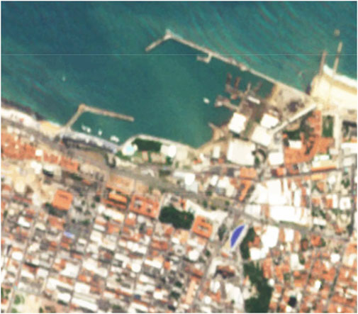
Figure 3. RapidEye satellite imagery as an example of HRSI - GSD = 5 m (RapidEye Overview - Earth Online, 2024).
Images of this quality enable operational assessment of the terrain in terms of the number and size of buildings, roads, movement of groups of vehicles, ships, etc. From the point of view of military operations, this information is crucial. Imaging in the very high resolution standard VHRSI (Very High Resolution Satellite Imagery) enables obtaining even more detailed image of the earth’s surface (for comparison shown in Figure 4), but it is associated with the need to use significantly larger telescopic structures, not suitable for implementation on nanosatellites, which does not result from contemporary technological possibilities, but from the laws of physics discussed earlier.
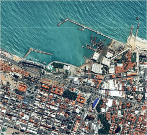
Figure 4. Pleiades satellite imagery as an example of VHRSI - GSD = 0.5 m [Pléiades | Very High-Resolution (50 cm) AIRBUS, 2024].
The assumption of the project was to achieve dimensions small enough to fit the entire telescope (optical system and electronics) in half the volume of an elementary 1U nanosatellite cube (Figure 5).
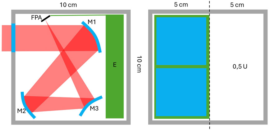
Figure 5. The assumed volumetric constrains for the designed telescope.
The required parameters of the telescope result from its planned application, and are therefore determined primarily by the orbit altitude, the width of the imaged strip of the Earth’s surface (swath) and the selected sensor (Table 1).
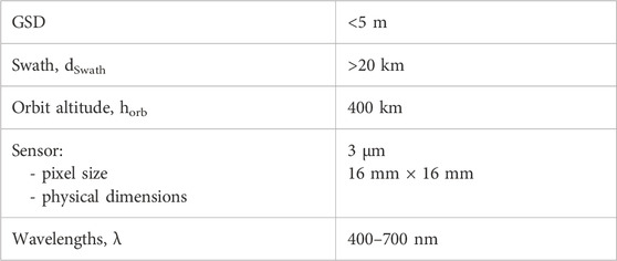
Table 1. Requirements for the designed telescope.
The telescope’s operational parameters clearly define the requirements for its basic paraxial optical parameters. First, achieving GSD below 5 m requires meeting the following relationship:
This means that the telescope’s focal length, f, should reach at least 24 cm for the selected sensor and orbit. Taking into account the GRD criterion, the following inequality must be met:
This means that the diameter of the telescope’s entrance pupil, D, should exceed 4.9 cm. Finally, the swath width determines the required field of view θfov, which can be estimated using the following relationship:
This means that the required field of view of the designed telescope must exceed 2.8o. Analysing the required optical parameters of the telescope determined above, we conclude that the project poses a significant challenge due to the relatively large aperture of f/4.9, a significant field of view at the level of 3o (or more) and a focal length value significantly exceeding the dimensions of the telescope and the dimensions of the 1U cube. In such a situation, also taking into account the wide spectral band, in the context of potential optical configurations of telescopes, it was reasonable to consider off-axis “folded” mirror systems, i.e., using the allocated geometric space to the maximum. Simultaneous fulfilment of all the optical requirements discussed above is not possible for conventional spherical or even aspherical optics. This is why the proposed solution is based on freeform mirrors.
Based on the above mentioned assumptions, a telescope model was constructed in Optic Studio environment. Three freeform mirrors were implemented, the surface of which was parameterized by a shifted polynomial equation presented before, with the highest order of coefficients being 30. The geometry of the mirrors’ location was selected adequately to the maximum allowable volume defined by the 0.5U cuboid (Figure 5). The error function (merit function, MF) was determined using geometric ray tracing, which allowed for the calculation of the size of the PSF focus spot (initial optimization phases) and the OPD wavefront error (final optimization phases).
The default approach, often used in the design of simple optical systems with a small number of degrees of freedom, in which all coefficients were varied, turned out to be ineffective. This resulted from the multidimensionality of the merit function, and consequently, the optimization algorithm achieved only local minima, which in turn were not globally optimal. For this reason, a different approach was used in this work, in which the number of variables was progressively increased during the optimization process. Thus, initially, attempts were made to optimize mirrors parameterized only by the basic radius of curvature. This did not give satisfactory results, however, the values of these radii were saved and in the next step the coefficients k were varied, which was associated with obtaining mirrors with conical surfaces. In this case, the obtained imaging quality was also significantly below the level of the diffraction limitation. In the next stages, the algorithm continued the optimization calculations by introducing the coefficients Aij of the freeform polynomial, so the mirrors took on a real freeform shapes. In each step, in addition to the error function itself, the numerical value of its derivative with respect to the iteration loop number was also calculated. The discussed design methodology is presented below (Figure 6).

Figure 6. The proposed design algorithm logic.
This algorithm was implemented in a computer ecosystem, with the cooperation of MATLAB and ZPL (Zemax Programming Language) software.
The presented algorithm was used to design the discussed telescope (result shown in Figure 7). The iterative loop stopped at the lap which corresponded to achieving satisfactory optical quality (full-field diffraction limit). The entire process took 8 min (Windows 11, AMD Ryzen 7 5800X 8-Core Processor, 32 GB RAM).
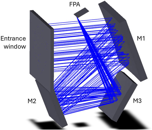
Figure 7. The designed telescope 3D visualisation.
The mirror surfaces of the designed telescope, as expected, do not have an axial symmetry (freeform mirrors). The figure below (Figure 8) presents the shapes of the surfaces of individual mirrors in the form of a distribution of the deviation from the closest sphere. It can be seen that these deviations are significant, especially for the M3 mirror, where the value of 1 mm is exceeded.
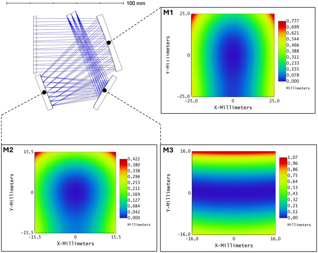
Figure 8. The designed telescope cross section and representations of M1 – M3 mirrors geometry.
Below (Figure 9) the imaging quality of the designed telescope is presented. It can be seen that the size of the spot diagram is in each case smaller than the diffraction limit ellipse. This confirms the high imaging quality of the designed telescope, which, given such a large field of view and high telephoto-ratio, deserves to be emphasized.
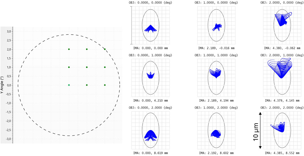
Figure 9. The field points used for the optimization process of the telescope–left, the corresponding ray spot diagrams - right (black ellipse - the diffraction limit).
Such conclusions are also confirmed by the MTF function (Figure 10). The level of 30% is achieved in this case for a spatial frequency of about 165 cycles/mm for the centre of the field of view and about 150 cycles/mm for the edge of the field of view. These values correspond to the optimal pixel size of 3 μm, which is in line with the design assumptions.
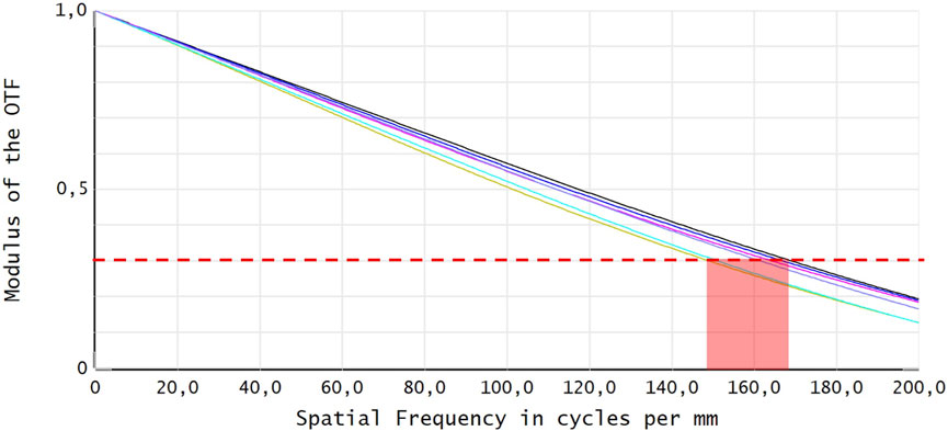
Figure 10. MTF curves of the designed telescope (black curve–diffraction limit).
The dimensions of the designed telescope allow, according to the assumptions, to fit in half of the elementary 1U nanosatellite cube (Figure 11). It is therefore an extremely compact optical design, while providing satisfactory imaging quality.
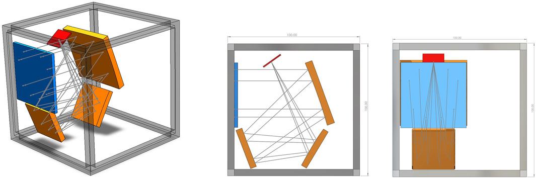
Figure 11. Visualisation of the designed telescope with respect to 1U cube dimensions.
Mechanical mountings of the designed mirrors are a separate technological problem, posing a major challenge in terms of thermal stability and resistance to vibration and overload. This topic deserves a separate publication.
Nevertheless, in order to verify the resistance of the designed optical system (in terms of maintaining high imaging quality) to its misalignment resulting from the potential relative shift of the mirrors and/or their mutual tilt, the so-called tolerance analysis was carried out. Tolerance calculation is an indispensable stage in the design of each optical system. This results from the fact that both the production of optical elements and the assembly of the entire optical system are always burdened with certain errors. As a result, the finally constructed optical system is not exactly the same as that which was designed. The purpose of the tolerance calculation is, among other things, to determine how large manufacturing/assembly errors we can afford to keep the satisfactory imaging quality of the optical system. This is particularly important for optical systems dedicated to space applications, due to their exposure to large mechanical overloads and thermal effects, which can lead to changes in the geometry of the optical system. For the purposes of the tolerance analysis, certain maximum values of deviations (errors) are assumed in relation to the position of the optical elements, their tilt, manufacturing accuracy, etc. These assumptions correspond to the implementation possibilities and potential consequences of external factors (temperature, shocks). Then, a simulation of many configurations of the designed optical system is carried out, with each such configuration characterized by randomly selected errors (Monte Carlo method) from the adopted ranges. As a result, it is possible to estimate how much of a decrease in imaging quality we can expect, for the assumed deviation values. In addition, the optical system parameters that are particularly sensitive to the deviation are identified.
In case of the designed telescope, the detailed tolerance analysis was performed in relation to potential shifts and tilts of mirrors. It turned out, that assuming standard achievable values of maximum deviations at the level of 0.01 mm and 0.02o, an increase in PSF size of about 1 µm can be expected. It should be considered a satisfactory result–the designed telescope shows a high resistance to potential misalignments (shifts of the mirrors and/or their mutual tilts). Such immunity, among other things, results from the low absolute optical power of the individual mirrors and the asymmetry of the mirror freeform geometry naturally adapted to the optical task. It can be seen that classic mechanical tolerances are sufficient to maintain the telescope’s imaging quality at a high level.
The tolerance analysis also gave an insight into the different sensitivities of individual mirrors M1 – M3 to misalignment. It was examined, how imaging quality degrades due to the separate tolerancing of each mirror with respect to tilts (Figure 12) and decentrations (Figure 13). It turned out that the M2 is the most critical component in terms of the required mechanical stability with respect to tilt around x- and y-axis, while the M3 mirror is the most sensitive to tilts around z-axis. Concerning mechanically related decentrations, the M2 mirror again revealed the highest sensitivity for mounting errors. What is worth to be noticed is that the most dramatic imaging quality degradation caused by M2 (0.02o tilt around x-axis and 0.01 mm y-direction decentration) is associated with misalignment-induced astigmatism. These two tolerances will therefore be the subject of special care when fabricating the mechanical system of the designed telescope.
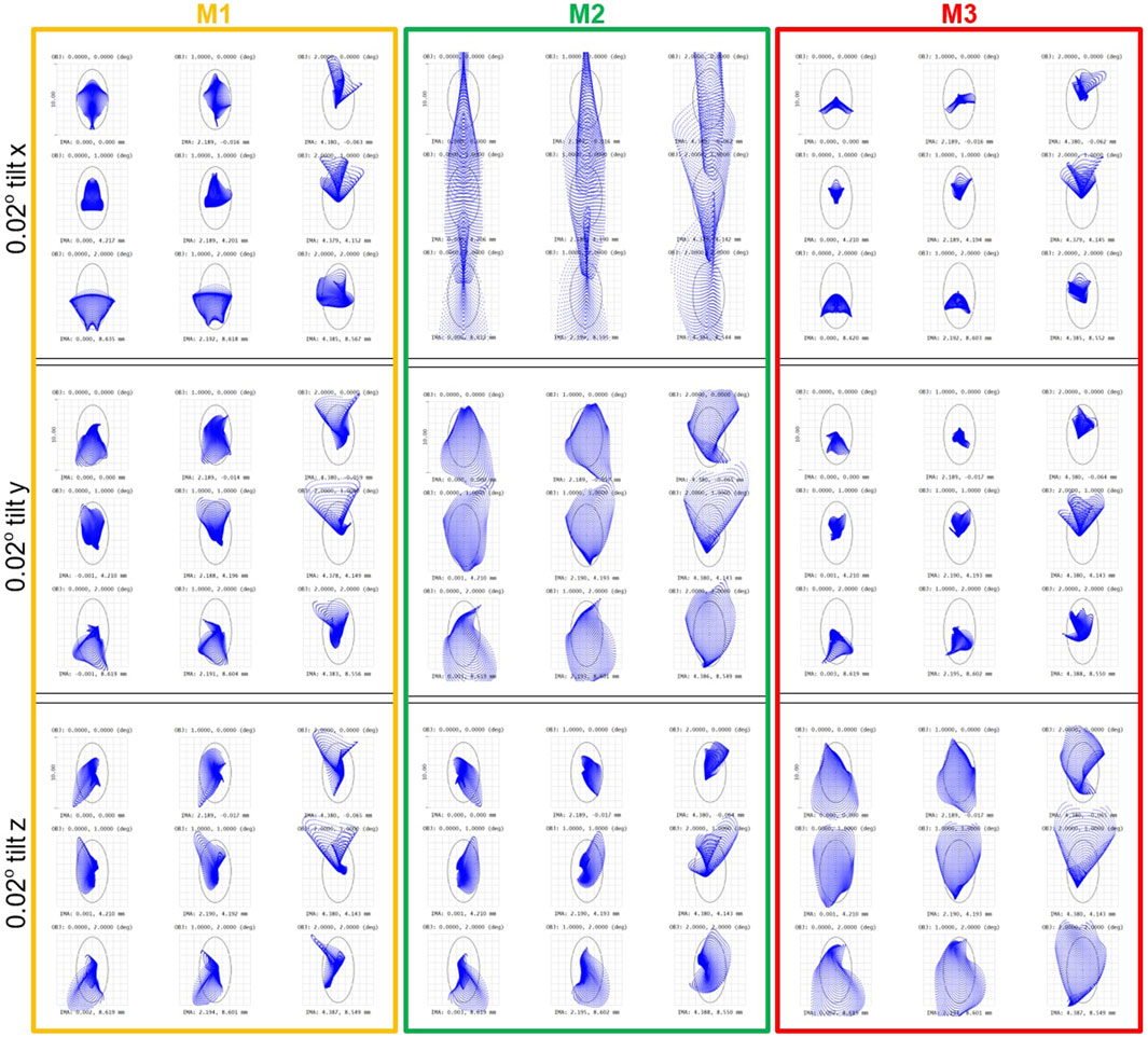
Figure 12. Ray spot diagrams showing the contributions of individual mirrors unintentional tilts to degradation of the designed telescope imaging quality.

Figure 13. Ray spot diagrams showing the contributions of individual mirrors unintentional decentrations to degradation of the designed telescope imaging quality.
The designed telescope is plane-symmetric. It results from the fact that all three mirrors and the sensor have been positioned in such a way, that they share a common plane of symmetry. This sub-type of freeform optics geometry have been extensively studied (Reshidko and Sasian, 2018). When designing plane symmetric systems, one can limit the degrees of freedom (optimization coefficients). It makes the optimization faster and more robust. Nevertheless, it should be underlined, that the proposed algorithm is not limited to this class of systems. In order to show this capability, the algorithm was used to design the modified version of the presented telescope, where the plane symmetry is broken by placing the sensor on the side of the main structure (Figure 14).
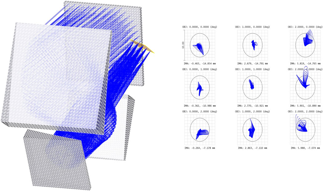
Figure 14. The designed telescope visualisation (left) and its imaging performance (right) in non-plane-symmetric configuration (sensor placed on one side of the structure).
The excellent imaging quality (diffraction limit) was also achieved in this configuration, however it required to increase the number of degrees of freedom by about 30% and the algorithm’s calculation time increased approximately by the same amount. It can be observed, that the freeform mirrors efficiently adopted to this new, asymmetric geometry.
The paper discusses the capabilities offered by the geometry of freeform surfaces in the aspect of space telescopes construction. Due to the lack of symmetry constraints, it is possible to obtain off-axis structures (without central obscuration) characterized by compact dimensions, excellent optical quality, wide field of view and high resistance to mechanical or thermal misalignment.
The paper presents a step-by-step method of designing a specific freeform telescope, dedicated to Earth imaging from LEO, in high resolution (GSD <5 m) and offering 20 km width of the observed strip. The aim of the project was to obtain the above parameters from a miniature system, fitting in half of an elementary 1U nanosatellite cube.
To implement the above task, an off-axis 3-mirror structure was proposed. In order to meet the imposed operational requirements, 25 cm focal length, f/4.9 aperture and at least 3o field of view had to be achieved. The spatial distribution of the three freeform mirrors takes full advantage of the available volume. The above parameters seemed to be unattainable for classic telescopes based on axisymmetric surfaces (tilted or off-axis sectioned). For this reason, the freeform mirror surfaces, described by multi-parameter series, were implemented. Due to the large number of variables, the use of standard optimization tools available in commercial optical software did not give positive results, because the multidimensional merit function featured a complicated structure, marked by many local minima, in which the optimization algorithm was stuck. For this reason, a dedicated algorithm was proposed to support this process. In the proposed methodology, the number of variables increases gradually during the optimization process. Also, the density of grid corresponding to variables sampling is increased upon approaching the merit function minimum. The proposed method enabled the design of an extremely compact freeform telescope with excellent optical imaging properties (diffraction limit across the full field of view). In addition, high resistance (low sensitivity of the obtained design) to potential misalignments was confirmed by Monte Carlo tolerance analysis, which is of particular importance in case of space applications.
The original contributions presented in the study are included in the article/supplementary material, further inquiries can be directed to the corresponding author.
JW: Conceptualization, Data curation, Formal Analysis, Methodology, Software, Visualization, Writing–original draft, Writing–review and editing.
The author(s) declare that financial support was received for the research and/or publication of this article. This work was supported by Polish Centre for Research and Development (NCBiR) under PIAST (Polish ImAging SaTellites) project, Grant No. DOB SZAFIR/10/A/022/01/2021.
The author express his gratitude to all colleagues participating in PIAST project and nano-satellite development.
The author declares that the research was conducted in the absence of any commercial or financial relationships that could be construed as a potential conflict of interest.
The author(s) declare that no Generative AI was used in the creation of this manuscript.
All claims expressed in this article are solely those of the authors and do not necessarily represent those of their affiliated organizations, or those of the publisher, the editors and the reviewers. Any product that may be evaluated in this article, or claim that may be made by its manufacturer, is not guaranteed or endorsed by the publisher.
AIRBUS (2024). Pléiades | very high-resolution (50cm) satellites imagery. Available online at: https://space-solutions.airbus.com/imagery/our-optical-and-radar-satellite-imagery/pleiades/.
Beier, M., Hartung, J., Peschel, T., Damm, C., Gebhardt, A., Scheiding, S., et al. (2015). Development, fabrication, and testing of an anamorphic imaging snap-together freeform telescope. Appl. Opt. 54 (12), 3530–3542. doi:10.1364/AO.54.003530
Benitez, P., Miñano, J. C., Chaves, J., and Santamaría, A. (2013). SMS freeforms for illumination. Adv. Opt. Technol. 2 (4), 323–329. doi:10.1515/aot-2013-0025
Bentley, J., and Olson, C. (2013b). Unobscured systems: aperture clearance. Field Guide Lens Des. doi:10.1117/3.934997.CH42
Broemel, A., Lippmann, U., and Gross, H. (2017a). Freeform surface descriptions. Part I: mathematical representations. Adv. Opt. Technol. 6 (5), 327–336. doi:10.1515/aot-2017-0030
Broemel, A., Liu, C., Zhong, Y., Zhang, Y., and Gross, H. (2017b). Freeform surface descriptions. Part II: application benchmark. Adv. Opt. Technol. 6 (5), 337–347. doi:10.1515/aot-2017-0031
Chen, W., Yang, T., Wang, Y., Cheng, D., Cheng, D., Wang, Y., et al. (2021). Generating starting points for designing freeform imaging optical systems based on deep learning. Opt. Express 29 (17), 27845–27870. doi:10.1364/OE.432745
deLoughery, T. J., Lauzon, C. D., Weber, J., Sims, K. H., Sims, K. H., Sims, K. H., et al. (2024). CubeSat Astrophotonics: lower cost, space-based optical astronomy using photonic integrated circuits. Adv. Photonics Congr. 2024, IW3B.4. doi:10.1364/IPRSN.2024.IW3B.4
Earth Online (2024). RapidEye Overview - earth online. Available online at: https://earth.esa.int/eogateway/missions/rapideye/description.
Fang, F., Cheng, Y., and Zhang, X. (2013). Design of freeform optics. Adv. Opt. Technol. 2 5–6, 445–453. doi:10.1515/aot-2013-0029
Figoski, J. W. (1986). Aberration characteristics of nonsymmetric systems. SPIE Proc., 0554 0554, 104–111. doi:10.1117/12.949203
Fischer, R., Tadic-Galeb, B., and Yoder, P. (2008). Optical system design. McGraw-Hill Education. Available online at: https://www.accessengineeringlibrary.com/content/book/9780071472487.
Forbes, G. W. (2012). Characterizing the shape of freeform optics References and links. doi:10.1364/OA_License_v1#VOR
Geyl, R., Ruch, E., Bourgois, R., Mercier-Ythier, R., Leplan, H., and Riguet, F. (2019). Freeform optics design, fabrication and testing technologies for Space applications. Int. Conf. Space Opt. — ICSO 2018 24, 24. doi:10.1117/12.2535944
Kumar, S., Tong, Z., and Jiang, X. (2022). Advances in the design and manufacturing of novel freeform optics. Int. J. Extreme Manuf. 4 (3), 032004. doi:10.1088/2631-7990/ac7617
Liu, J., Hugot, E., Muslimov, E., and Lombardo, S. (2024). Compact off-axis reflective optical system design combining freeform mirror and freeform detector. Opt. Commun. 565, 130675. doi:10.1016/J.OPTCOM.2024.130675
Liu, Y., Bauer, A., Viard, T., and Rolland, J. P. (2021). Freeform hyperspectral imager design in a CubeSat format. Opt. Express 29 (22), 35915. doi:10.1364/oe.439530
Meng, Q., Wang, H., Liang, W., Yan, Z., and Wang, B. (2019). Design of off-axis three-mirror systems with ultrawide field of view based on an expansion process of surface freeform and field of view. Appl. Opt. 58 (3), 609–615. doi:10.1364/AO.58.000609
Meng, Q., Wang, H., Wang, K., Wang, Y., Ji, Z., and Wang, D. (2016). Off-axis three-mirror freeform telescope with a large linear field of view based on an integration mirror. Appl. Opt. 55 (32), 8962–8970. doi:10.1364/AO.55.008962
Muslimov, E., Hugot, E., Jahn, W., Vives, S., Ferrari, M., Chambion, B., et al. (2017). Combining freeform optics and curved detectors for wide field imaging: a polynomial approach over squared aperture. Opt. Express 25, 14598–14610. doi:10.1364/OE.25.014598
Peschel, T., Gebhardt, A., Risse, S., Walter, I., Sebastian, I., Krutz, D., et al. (2017). Design of an imaging spectrometer for earth observation using freeform mirrors. Int. Conf. Space Opt. — ICSO 2016 161, 161. doi:10.1117/12.2296156
Reshidko, D., and Sasian, J. (2018). Method for the design of nonaxially symmetric optical systems using free-form surfaces. Opt. Eng. 57 (10), 1. doi:10.1117/1.OE.57.10.101704
Rolland, J. P., Davies, M. A., Suleski, T. J., Evans, C., Bauer, A., Lambropoulos, J. C., et al. (2021). Freeform optics for imaging. Optica 8 (2), 161. doi:10.1364/optica.413762
Shack, R. V., and Thompson, K. (1980). Influence of alignment errors of A telescope system on its aberration field. SPIE Proc. 0251 (0251), 146–153. doi:10.1117/12.959464
Shiroma, W. A., Martin, L. K., Akagi, J. M., Akagi, J. T., Wolfe, B. L., Fewell, B. A., et al. (2011). CubeSats: a bright future for nanosatellites. Open Eng. 1 (1), 9–15. doi:10.2478/s13531-011-0007-8
Takaki, N., Bauer, A., and Rolland, J. P. (2018). Degeneracy in freeform surfaces described with orthogonal polynomials. Appl. Opt. 57 (35), 10348. doi:10.1364/ao.57.010348
Talpur, T., and Herkommer, A. (2016). Review of freeform TIR collimator design methods. Adv. Opt. Technol. 5 (Issue 2), 137–146. doi:10.1515/aot-2016-0003
Ye, J., Chen, L., Li, X., Yuan, Q., and Gao, Z. (2017). Review of optical freeform surface representation technique and its application. Opt. Eng. 56 (11), 1. doi:10.1117/1.oe.56.11.110901
Keywords: CubeSat, telescope design, satellite imagery, three-mirror anastigmat, freeform optical design
Citation: Wojtanowski J (2025) High resolution satellite imaging 0.5U-size freeform telescope for CubeSat. Adv. Opt. Technol. 14:1568420. doi: 10.3389/aot.2025.1568420
Received: 29 January 2025; Accepted: 10 March 2025;
Published: 21 March 2025.
Edited by:
Allen Yi, The Ohio State University, United StatesReviewed by:
Stefan Bäumer, Netherlands Organisation for Applied Scientific Research, NetherlandsCopyright © 2025 Wojtanowski. This is an open-access article distributed under the terms of the Creative Commons Attribution License (CC BY). The use, distribution or reproduction in other forums is permitted, provided the original author(s) and the copyright owner(s) are credited and that the original publication in this journal is cited, in accordance with accepted academic practice. No use, distribution or reproduction is permitted which does not comply with these terms.
*Correspondence: Jacek Wojtanowski, amFjZWsud29qdGFub3dza2lAd2F0LmVkdS5wbA==
Disclaimer: All claims expressed in this article are solely those of the authors and do not necessarily represent those of their affiliated organizations, or those of the publisher, the editors and the reviewers. Any product that may be evaluated in this article or claim that may be made by its manufacturer is not guaranteed or endorsed by the publisher.
Research integrity at Frontiers
Learn more about the work of our research integrity team to safeguard the quality of each article we publish.