 Daniel Flamm
 Julian Hellstern2
- 1TRUMPF Laser- und Systemtechnik GmbH, Ditzingen, Germany
- 2TRUMPF Laser GmbH, Schramberg, Germany
A structured light concept is reported enabling to distribute a large number of focus copies at arbitrary positions in a working volume. Applying this holographic 3D-beam splitter concept to ultrashort laser pulses allows to deposit energy along accelerating trajectories in the volume of transparent materials. Based on the entirety of the volume modifications created in this way, the material can be separated, for example, to create chamfered glass edges. These photonic tools impress with enormous versatility, which enable equally diverse application strategies ranging from cutting and welding to data storing.
1 Introduction
Since the theoretical description (Siviloglou and Christodoulides, 2007) and experimental realization of the optical Airy beam by Siviloglou et al. (2007), accelerating beams have caused a stir in the scientific world as they appear to violate the fundamental property of straight light propagation (Efremidis et al., 2019). Since then, a large number of applications have been proposed and realized (Efremidis et al., 2019) including ultrafast micromachining along curves already demonstrated in 2012 by Mathis et al. (2012). The self-healing properties of this class of radiation are shown to be particularly useful, as local material modifications usually prevent undisturbed light propagation. To the same extent as known from non-diffracting beams (McGloin and Dholakia, 2005), Airy beam profiles reconstitute themselves behind obstacles including highest peak intensities, enabling particularly efficient processing of substrates in a single pass (Mathis et al., 2012). Therefore, this class of radiation is also called non-diffracting second type (Baumgartl et al., 2008; Woerdemann, 2012).
The Airy beam and related caustic-based concepts (Froehly et al., 2011; Efremidis et al., 2019) certainly owe their academic triumph (the keyword “Airy beam” yields several thousand papers at google scholar) to the general accessibility of liquid-crystal-on-silicon-based spatial light modulators (SLMs). In most cases, matched phase masks, for example, cubic phase modulations (far-field generation) (Siviloglou et al., 2007) or the well-known “3/2-phase pattern” (near-field generation) (Cottrell et al., 2009), displayed by SLMs and embedded in simple focusing (Siviloglou et al., 2007) or imaging (Froehly et al., 2011) optics form the optical setup. As the spatial resolution of today’s SLMs allows only a few degree in diffraction angles, the degree of curvature is mainly determined by the numerical aperture (NA) of the focusing used. If, for example, maximum angle differences of the tangents to the curved surface of 90-deg are to be aimed, the required NA is already 1, cf. Figure 1. Such “strong” focusings to generate nonparaxial accelerating beams (Froehly et al., 2011; Zhang et al., 2012) can of course be realized by conventional microscope objectives, see, for example, the NA-0.8-micromachining experiment in Ref. (Mathis et al., 2012). For industry-grade materials processing, however, this entails various disadvantages, e.g., with respect to working distance, focus position tolerance, or lens contamination or collisions. To name just one example: Considering a microscope objective with NA = 0.8, the resulting working distance is typically well below 1 mm. The risk of constant lens contamination by micro-debris during materials processing is very high.
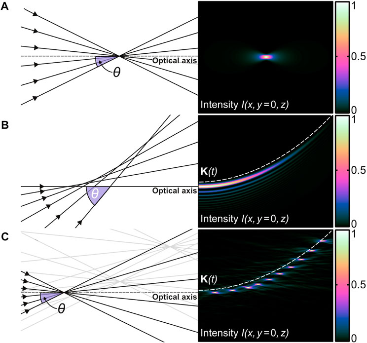
FIGURE 1. Ray optical and wave optical representation of different focus distributions propagating in vacuum without applying an optical potential. As for the wave optical case, normalized intensity cross sections
Recently, several studies have been published in which glass edges formed with accelerating and tilted non-diffracting beams have been fabricated in a single pass, see (Jenne et al., 2018; Sohr et al., 2021; Ungaro and Liu, 2021). The edge shapes produced and in particular the only slightly reduced edge angles support our argument that a more advanced tool is needed enabling trajectories with 45-deg tangential angles to the surface.
Our solution for a photonic shaping tool, i.e., the generation of high intensities along arbitrary curves or surfaces to modify materials, is based on distributing a large number of focus copies in the processing volume. Here, the desired spatial shape is sampled by discrete foci whose entirety form the total focus distribution, see Figure 1C. We will demonstrate that almost arbitrary tangential angles to the accelerated trajectory are possible, as well as the sampling of arbitrarily curved surfaces. The requirements on the numerical aperture of the focusing objectives are moderate, so that large working distances and large working volumes are possible at the same time. The ability to process large working volumes simultaneously allows to fully exploit the power or energy performance of industrial laser systems and to develop particularly efficient laser application strategies. In the paper, the two main enabler of this concept, the central beam splitting element, here, again realized with, for example, flexible SLMs, cf. Section 2, and the advanced focusing unit, cf. Section 3, are introduced in detail.
We have identified the processing of transparent materials as a main application of this concept. Here, we can use the high intensities generated by ultrashort laser pulses, to deterministically deposit energy in the volume of glasses with light. At the resulting modified areas, the material can be separated, e.g., by applying a selective etching strategy. In Section 4, we will apply our shaping tools to cut display glasses with tailored edges in a single pass. The substrates with laser-chamfered edges show enhanced mechanical properties when it comes to an impact or when the sample already exhibits smallest defects from former fabrication steps (Flamm et al., 2022a). Here, the photonic shaping tool has the potential to replace conventional techniques based on mechanical grinding and polishing (Bukieda et al., 2020).
2 Holographic 3D-beam splitter
Industrial ultrafast laser sources providing multi-kilowatts of average powers and several tens-of-millijoules pulse energies will be available soon (Sutter et al., 2019; Dominik et al., 2021; Mans et al., 2021; Dominik et al., 2022). These laser systems enable the development of completely new application strategies, such as, e.g., single-pass, millimeter-scaled cutting of glasses with m/s-feed rates (Hosseini and Herman, 2016; Jenne et al., 2020). This simple example illustrates the need for sophisticated optical concepts, since the simultaneous processing of the entire substrate thickness using an adapted non-diffracting beam (Jenne et al., 2020), is the key to make efficient use of the extreme laser parameters. Therefore, processing optics are of particular interest that distribute high laser intensities into large volumes, cf. glass cutting example (Kumkar et al., 2016; Jenne et al., 2020), or onto large surfaces (Tillkorn et al., 2018; Flamm et al., 2022b) in order to increase throughput through parallel processing and, thus, to exploit the full performance of the laser source (Kumkar et al., 2017). Based on well-known techniques for parallel data recording and storing (Streibl, 1989; Gu et al., 2014; Ren et al., 2014; Zhu et al., 2014), here, we use concepts to generate multifocal arrays and extend them to arbitrarily place a multitude of foci within a millimeter-scaled working volume (Jesacher and Booth, 2010; Simmonds et al., 2011).
Displacing a focal spot from its original geometric focus position behind a lens is achieved by introducing phase modifications to the illuminating optical field. In terms of Zernike polynomials (Noll, 1976), a proper choice of tip/tilt modes in combination with a defocus allows to control the transverse
Transverse shifting the jth-order focus is achieved by setting a linear blaze grating
and yields a transverse displacement according to
Longitudinal displacement Δzj of the focal spot of order j is realized by introducing the defocus mode (Noll, 1976) using, e.g., a holographic lens transmission with focal length fj (Goodman, 2005).
In paraxial approximation the longitudinal shift is directly deduced from
Combinations of transverse
In general, this multiplexing scheme will yield a complex valued transmission
The spatial resolution of today’s SLMs already allows to split the raw beam into several hundred volume-split focus copies. Depending on the target focus distribution and applied spatial frequencies, efficiencies are achieved between 70 % and 90 %. The number of spots can be further increased when using stationary diffractive optical elements (DOEs) to realize Ttot. Typically, after having applied soft quantization (Wyrowski, 1989) on available phase levels the diffraction efficiency reaches values comparable to those when using SLMs. However, the amount of unmodulated light is significantly reduced when DOEs are employed. Two selected examples of phase modulations Φtot defining Ttot are depicted in Figure 2. In both cases phase quantization on eight levels were applied to Φtot optimized for the laser lithographic realization in fused silica.
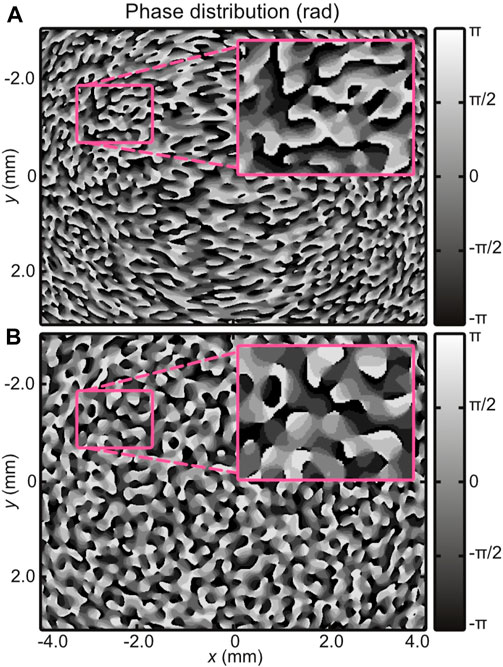
FIGURE 2. Central details of phase modulations defining the phase-only transmission functions
The corresponding focus distributions of these two phase holograms can be seen in Figures 3, 4 where tens-of-spots are distributed along a spiral-like trajectory and a cone surface, respectively. After having focused the spot distribution in a sub-millimeter-scaled working volume using an NA-0.4-microscope objective and a 2f-like configuration, the same optical concept was used in a reversed way to perform the laser beam characterization with an NA of 0.4 (Rave et al., 2021). The measured data confirms a successful volume-beam splitting concept with highest spot densities and uniformities along the accelerating trajectory and the cone surface, respectively.
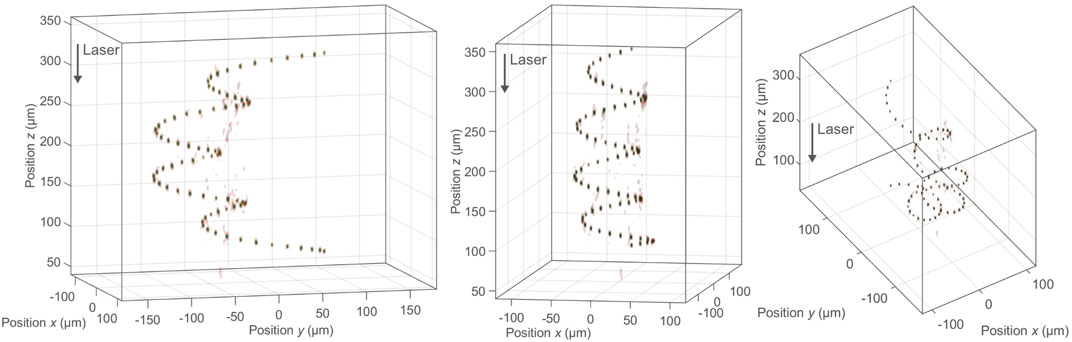
FIGURE 3. Measured intensity
in an isosurface representation
(Jesacher and Booth, 2010) of a 3D-focus
distribution consisting of 70 spots and
following a screw-like trajectory
for
Micrometer-scaled laser beam characterization
was achieved by microsopy of the focal volume
using a reversed focusing setup similar to
the one shown in Rave et al. (2021). Every
subfigure depicts the same focus distribution
from different perspectives.
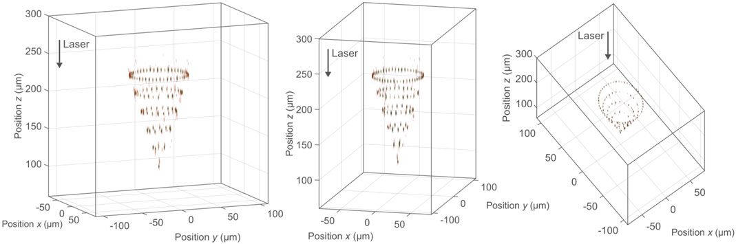
FIGURE 4. Measured intensity
As can be seen from the two measurements (Figures 3, 4) as well as from the simulation depicted in Figure 1C, holographic beam splitting produces undesired side orders that can also reach significant relative intensities of >10%. The actual value of the unwanted local intensity maxima depends on the spot density and arrangement and can be suppressed by the iterative design algorithm. Please note that the spot density cannot be chosen arbitrarily high, as interference of the multiplexed signals will cause beating effects reducing uniformity. However, as will be demonstrated in Section 4, neither discrete sampling nor unwanted side orders have a negative impact on the machining result. The simultaneous introduction of the modifications ensures their interconnection and a continuous, etch access, although the desired trajectory does not exhibit continuous high intensities. Peak intensities in unwanted diffraction orders are below the substrate’s nonlinear absorption threshold and do not lead to volume modifications. A technique for further increasing spot density while suppressing interference effects is proposed in Flamm and Kumkar (2022). Here, polarization beam splitting is applied providing focus copies with alternating polarization states.
3 Large-working-volume focusing units
In the foregoing section, we discussed the basics of simultaneously generating a large number of spots in a given working volume along a desired curved trajectory or surface. To handle the high numerical complexity of wave-optical hologram design (Flamm et al., 2019; Flamm et al., 2021), we make use of ideal optical elements (thin-element approximation) as well as the angular spectrum method and far-field operators (Goodman, 2005). Now, the question arises whether a real focusing unit is in principle capable of delivering diffraction-limited focal spots in the required working volume. Ideally, the uniformity of the spot distribution, cf. Figure 3, is not affected by the real objective and the single spots show radial symmetric profiles without preferential direction. In addition, an industrially suitable machining is aimed where the focusing unit efficiently provides the focus shape with a sufficient working distance and is able to resist ultrashort laser pulses in the millijoule class (Flamm et al., 2021; Kaiser et al., 2022). In the following, we will focus on micromachining of display glasses of d ≈ 0.5 mm thickness, cf. Section 4, and, thus require a working volume of V ≈ d3 (please note, that our beam splitter concept is not restricted to the micrometer regime and can be scaled with the focal length of the focusing unit). Considering cleaving of display glasses with non-diffracting beams (straight glass edges) (Ahmed et al., 2008; Marjanovic et al., 2017; Jenne et al., 2020), we aim for focus dimensions in the range of
As mentioned above, the demands on the imaging performance of the microscope lenses are high as aberrations within the comparatively large working volume should be negligibly small. In practical applications, however, a large axial and lateral working volume lead to an inherent physical limitation and conflicts especially high numerical apertures. An absence of lateral aberrations requires the system to satisfy the Abbe sine condition (Braat, 1997). Hence residual spherical aberrations will occur along the axial dimension. On the other hand, the absence of axial aberrations requires the Herschel condition to be satisfied resulting in remaining lateral aberrations mainly composed by coma (Braat, 1997). In detail, here, the rotational symmetry of the individual focal points is essential for a controlled laser modification process as non-radial symmetric spots can generate cracks whose orientation may not be aligned with the processing direction. Please note that if alignment of the preferred direction induced by non-axisymmetric focal points and the processing direction is ensured the glass separation step can be facilitated significantly (Jenne et al., 2020; Kumkar et al., 2021). However, laser modifications with uncontrolled crack orientation usually result in poor edge quality. Therefore, the microscope lenses have been designed to satisfy the sine condition and weak spherical aberrations remain along the axial range (Kaiser et al., 2022).
To demonstrate the need for a multi-lens focusing objective when processing large volumes with NAs above 0.2, ray- and wave-optical simulations were performed shown in the scenario of Figure 5. Here, the performance of a conventional (single lens) asphere (top) and a microscope objective (six lenses and cover glass, bottom) can be directly compared. The simple optical setup comprises mainly the beam splitter and the focusing unit in a 2f-like arrangement (Flamm et al., 2021; Flamm et al., 2022a), represented by black boxes, see left hand side. As mentioned, for the tailored-edge cleaving of glasses relevant for display industry, a working volume is aimed with
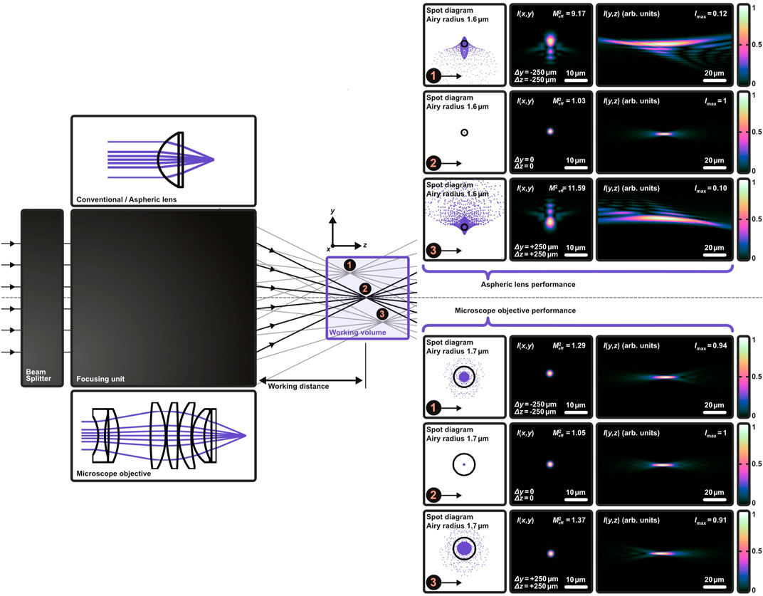
FIGURE 5. Comparison of the focusing performance of a conventional single aspheric lens (top) and an adapted multi-lens microscope objective (bottom) for large volume processing with holographic 3D-beam splitters (Kaiser et al., 2022). The effective focal length and the numerical aperture is set to feff =10 mm and NA = 0.45 for both cases. The beam splitter and the focusing unit form the optical setup in a 2f-like configuration (Flamm et al., 2021; Flamm et al., 2022a; Kaiser et al., 2022) denoted by the black boxes (left). A working volume of  at
at  at
at  at equals the geometrical focus of both focusing units. For simplicity, the distribution of the spots is kept at two dimensions and x = 0 is set for all three cases. The ray- and wave-optical evaluation of the resulting foci confirms the need for a multi-lens microscope objective as we achieve diffraction limited spots even at the limits of the working volume. The poor focusing performance of the single aspherical lens can be seen especially for the two large focus shifts, cases and Here, the transverse intensity profile
Upon closer inspection, one can also see the impact of our design strategy for the objective unit satisfying the Abbe sine condition (Braat, 1997). In all three cases, the intensity distributions are radially symmetric and marginally modulated on axis, see bottom right of Figure 5—a typical behavior for slightly spherically aberrated spots. Thus, the Herschel condition is not fully satisfied in the three cases shown. However, these aberrations are negligible since the peak intensities and focal shapes are mainly responsible for useful laser modifications. Here, the loss in peak intensity is smaller than 10% when using the microscope objectives, see bottom right. The beam propagation factor
The situation using the single lens asphere is likewise clear. Optimized for the position in the geometrical focus, see middle case depicted on the top right of Figure 5, the two other cases show strong typical coma and astigmatism aberrations at the edges of the working volume. The spot profiles are no longer radially symmetric and show significant peak intensity losses. Thus, neither the Abbe sine, nor the Herschel condition is satisfied (Burge et al., 2010). This is confirmed by corresponding
4 Single-pass tailored-edge glass cleaving
With the previous sections (Sections 2, 3) we have laid the hardware fundamentals for advanced volume processing of transparent materials. Using our photonic shaping tool, various processing strategies are conceivable ranging from welding (Zimmermann et al., 2013) to data storing (Zhang et al., 2014) and waveguide writing (Nolte et al., 2003). In our opinion, however, the cutting of display glass with a tailored edge represents the greatest potential from an economical point of view.
Irrespective of whether a conventional scribe and break process (Nisar et al., 2013) or a laser-based approach is used for glass cutting (Jenne et al., 2020), the first process result is always a substrate with a vertical edge. These manufactured smallest edge radii represent the greatest weak points of brittle-hard materials, as stresses accumulate at the 90-deg corners which lead to chippings and cracks in the event of an impact. Substrates with reduced tangential edge angles (Flamm et al., 2022a), as known from beveled, chamfered or C-shaped edges, will be characterized by higher mechanical stabilities (Marjanovic et al., 2019; Bukieda et al., 2020; Flamm et al., 2022a).
If a glass substrate is cut to size, various further process steps are needed, such as cleaning, polishing, hardening, etc. The longer and more complex the further processing of a substrate, the more probable it is that defects will occur. Here, too, a shaped glass edge will be very effective in protecting the substrate from cracks. Chamfering is therefore highly desirable right from the first process steps. Laser-based processing becomes particularly attractive when cutting and chamfering can be performed in a single processing step (Flamm et al., 2022a).
Our photonic shaping tool is designed to take the shape of a desired edge geometry. Thus, several transmission functions Ttot, cf. Eq. 3, haven been iteratively determined and displayed by the SLM acting as flexible holographic 3D-beam splitter to fabricate glass substrates with, for example, chamfered and C-shaped egdes. Ultrashort laser pulses emerged from a TruMicro Series 2000 laser (Jansen et al., 2018) are illuminating this central beam splitting element in a 2f-like configuration, cf. Figure 5. During machining, laser parameters were set to generate type-III-like modifications (Itoh et al., 2006) inside the glass substrate. Here, a pulse energy of ≲150 μJ was equally distributed to picosecond pulse trains (Herman et al., 2003; Kerse et al., 2016). The feed rates were selected to produce a modification pitch of ∼5 μm. Results of the first step of our glass chamfering approach, the laser modification step using volume-split spots, can be inspected in Figure 6. Shown here is a microscope image taken perpendicularly from the edge of an unhardened 550 μm-thick Corning Gorilla® glass substrate. While focusing was achieved parallel to the z-axis, see the coordinate system, the workpiece was positioned in y-direction with respect to the optical head.
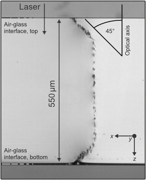
FIGURE 6. Microscope image of the edge of an unhardened 550 μm-thick Corning Gorilla® glass substrate with laser-induced modifications following a chamfered trajectory. Spatially separated type-III-regime modifications (Itoh et al., 2006) caused by the split Gaussian foci are apparent which are at least partially connected by cracks (Jenne et al., 2020; Flamm et al., 2022a). Tangential angles to the modified contour induced within a single pass are reduced down to α ≲ 45°. Processing was achieved parallel to the y-axis, see coordinate system. Employed pulse energy in burst mode was about 100 μJ—barely enough to generate visible volume modifications at all spots. Please note that not all modifications can be clearly identified by naked eye or with a light microscope, respectively.
The holographically split Gaussian foci cause modifications, which are partially separated and partially overlapping and which clearly follow the desired chamfer contour. All modifications are aligned parallel to the optical axis and project into the good part of our workpiece, depending on the respective position on the trajectory. This behavior is typical for type-III-regime modifications generated by Grossmann et al. (2016), Bergner et al. (2018). Here, however, due to the simultaneous introduction of a large number of damages, an interaction among the modifications also takes place. Please note that, as can be seen from the microscope image, defects are at least partially connected by cracks. This points out the importance of not considering the modifications generated by the focus copies in isolation from each other, but rather to treat the entirety of the foci as one focus distribution. Crucial for the presented method is the simultaneity when introducing the material modifications. Only the simultaneous impact of many focal points on the material produces connected modifications without shielding effects, which in turn enable the substrate separation in the first place (Flamm et al., 2022a).
Please note that the laser parameters given in this study represent useful values and may form the basis for future investigations. However, we do not claim to have found the optimal parameters. Depending on the substrate geometry and material, adapted laser parameters have to be found. Furthermore, it will strongly depend on which separation process (e.g., chemical versus thermal) is actually aimed at. Especially for thermal separation with CO2-laser radiation, which is highly relevant from an industrial point of view, the required laser parameters will be completely different and further parameter studies are necessary (Flamm et al., 2022a).
Various strategies are known for the second processing step, such as the application of mechanical loads (Jenne et al., 2020) or the induction of thermal stresses from CO2-laser radiation (Nisar et al., 2013). It is also well understood that different types of laser-induced modifications, for example, type II modifications in fused silica (Hermans et al., 2014; Gottmann et al., 2017), can feature much larger, etch rates than the untreated glass volume
Our selective laser etching strategy is based on the application 30 wt.-% KOH solution to the laser-modified substrate in an ultrasonic bath at 80°C (Kaiser et al., 2019; Rave et al., 2021). After an etching time of
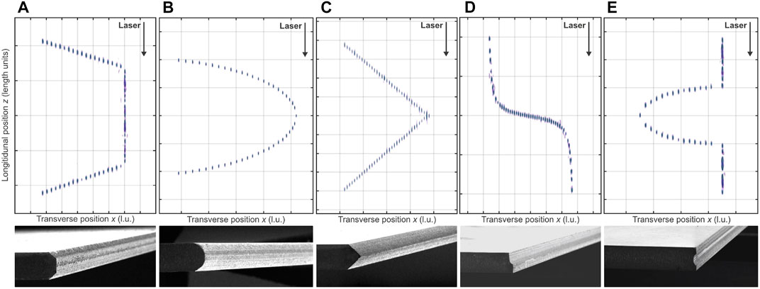
FIGURE 7. Examples for 2D-focus distributions (top, the third spatial dimension is not used here) and corresponding processing results in 550 μm-thick Corning Gorilla glass (bottom) (Kaiser et al., 2022). In each case, the z-axis corresponds to the propagation direction. Length dimensions not shown on purpose. For the sake of clarity, the spots are weighted equally. Depending on the material, edge geometry and separation strategy, an adapted weighting is reasonable and possible. The first two examples of a chamfered (A) and a C-shaped edge (B) follow the argumentation of edge protecting due to a reduced tangential angle to the surface (Flamm et al., 2022a) which read as 45-deg in (A) and less than 30-deg in (B). The last three cases of an apex shape with 90-deg apex angle (C), (smoothed) step profile (D), and inverse half-circle shape (E) may be beneficial for auto-centering or flush-closing tasks (Kaiser et al., 2022).
5 Conclusion
We have introduced photonic tools in which the focus distribution generated from a processing optics take the shape of the workpiece to be processed. Here the two main enabler of the optical head, the holographic 3D-beam splitter and the large-working volume focusing unit were presented and corresponding design strategies were discussed. The possible shapes that this sophisticated laser tool can exhibit are enormously diverse and exceed those from well-known techniques where accelerating beams are used, especially with respect to possible radii of curvature. Applying this approach to ultrashort laser pulses allows to deposit energy at arbitrary locations in a glass volume. At the resulting material modifications the substrate can be separated, for example, by chemical means. The uniqueness of our laser optical concept is demonstrated by presenting selected processing highlights useful for edge-protecting applications. Here, cutting and edge-chamfering was performed within a single pass and with the potential for m/s feed rates.
Data availability statement
Data inquiries can be directed to the corresponding author.
Author contributions
All authors listed have made a substantial, direct, and intellectual contribution to the work and approved it for publication. MaK did the experimental work.
Conflict of interest
Authors DF, MyK, MaK, and JK were employed by TRUMPF Laser- und Systemtechnik GmbH and Authors JH and CT were employed by TRUMPF Laser GmbH.
Publisher’s note
All claims expressed in this article are solely those of the authors and do not necessarily represent those of their affiliated organizations, or those of the publisher, the editors and the reviewers. Any product that may be evaluated in this article, or claim that may be made by its manufacturer, is not guaranteed or endorsed by the publisher.
This manuscript was transferred from Walter De Gruyter GmbH to Frontiers Media SA. The peer review for this paper was conducted in full by Walter De Gruyter GmbH. In accordance with their peer review, editor names and reviewer names have not been published. For any queries regarding the peer review of this manuscript, please contact YWR2YW5jZWRvcHRpY3MuZWRpdG9yaWFsLm9mZmljZUBmcm9udGllcnNpbi5vcmc=.
References
Ahmed, F., Lee, M. S., Sekita, H., Sumiyoshi, T., and Kamata, M. (2008). Display glass cutting by femtosecond laser induced single shot periodic void array. Appl. Phys. A 93 (1), 189–192. doi:10.1007/s00339-008-4672-2
Arrizón, V., Ruiz, U., Carrada, R., and González, L. A. (2007). Pixelated phase computer holograms for the accurate encoding of scalar complex fields. J. Opt. Soc. Am. A 24 (11), 3500–3507. doi:10.1364/josaa.24.003500
Baumgartl, J., Mazilu, M., and Dholakia, K. (2008). Optically mediated particle clearing using Airy wavepackets. Nat. photonics 2 (11), 675–678. doi:10.1038/nphoton.2008.201
Bergner, K., Seyfarth, B., Lammers, K., Ullsperger, T., Döring, S., Heinrich, M., et al. (2018). Spatio-temporal analysis of glass volume processing using ultrashort laser pulses. Appl. Opt. 57 (16), 4618–4632. doi:10.1364/ao.57.004618
Braat, J. J. (1997). “Abbe sine condition and related imaging conditions in geometrical optics,” in Fifth International Topical Meeting on Education and Training in Optics, 3190, Delft, Netherlands, 08 December 1997 (International Society for Optics and Photonics), 59–64.
Bukieda, P., Lohr, K., Meiberg, J., and Weller, B. (2020). Study on the optical quality and strength of glass edges after the grinding and polishing process. Glass Struct. Eng. 5, 411–428. doi:10.1007/s40940-020-00121-x
Burge, J. H., Zhao, C., and Dubin, M. (2010). “Use of the Abbe sine condition to quantify alignment aberrations in optical imaging systems,” in International Optical Design Conference, WY, United States, 09 September 2010 (Optical Society of America), ITuD5.
Cottrell, D. M., Davis, J. A., and Hazard, T. M. (2009). Direct generation of accelerating Airy beams using a 3/2 phase-only pattern. Opt. Lett. 34 (17), 2634–2636. doi:10.1364/ol.34.002634
Dominik, J., Jaksic, J., Ertel, K., Dannecker, B., Scharun, M., Nagel, S., et al. (2022). “Thin-disk multipass amplifier for 100 mJ class, multi-kW high intensity lasers,” in High Intensity Lasers and High Field Phenomena, Budapest Hungary, 26 January 2022 (Optica Publishing Group), HW4B.
Dominik, J., Scharun, M., Rampp, M., Dannecker, B., Bauer, D., Metzger, T., et al. (2021). “Thin-disk multipass amplifier for kilowatt-class ultrafast lasers above 100 mJ,” in The European Conference on Lasers and Electro-Optics, Munich, Germany, 21-25 June 2021 (IEEE).
Efremidis, N. K., Chen, Z., Segev, M., and Christodoulides, D. N. (2019). Airy beams and accelerating waves: An overview of recent advances. Optica 6 (5), 686–701. doi:10.1364/optica.6.000686
Flamm, D., Grossmann, D. G., Jenne, M., Zimmermann, F., Kleiner, J., Kaiser, M., et al. (2019). “Beam shaping for ultrafast materials processing,” in Laser Resonators, Microresonators, and Beam Control XXI, 10904, San Francisco, California, United States, 04 March 2019 (International Society for Optics and Photonics), 109041G.
Flamm, D., Grossmann, D. G., Sailer, M., Kaiser, M., Zimmermann, F., Chen, K., et al. (2021). Structured light for ultrafast laser micro-and nanoprocessing. Opt. Eng. 60 (2), 025105. doi:10.1117/1.oe.60.2.025105
Flamm, D., Hellstern, J., Heimes, A., Zimmermann, F., Ghazagh, A., Wohletz, J., et al. (2022b). “Multi-mj ultrafast laser machining with flexible multi-spot patterns,” in High-Power Laser Materials Processing: Applications, Diagnostics, and Systems XI, 11994, San Francisco, California, United States, 04 March 2022 (SPIE), 146–152.
Flamm, D., Kaiser, M., Feil, M., Kahmann, M., Lang, M., Kleiner, J., et al. (2022a). Protecting the edge: Ultrafast laser modified C-shaped glass edges. J. Laser Appl. 34 (1), 012014. doi:10.2351/7.0000592
Flamm, D., and Kumkar, M. (2022). Method for the laser processing of a workpiece, processing optical unit and laser processing apparatus. United States. US Patent 20220258284.
Flamm, D., Schulze, C., Brüning, R., Schmidt, O. A., Kaiser, T., Schröter, S., et al. (2012). Fast M2 measurement for fiber beams based on modal analysis. Appl. Opt. 51 (7), 987–993. doi:10.1364/ao.51.000987
Froehly, L., Courvoisier, F., Mathis, A., Jacquot, M., Furfaro, L., Giust, R., et al. (2011). Arbitrary accelerating micron-scale caustic beams in two and three dimensions. Opt. express 19 (17), 16455–16465. doi:10.1364/oe.19.016455
Goodman, J. W. (2005). Introduction to fourier optics. 3rd ed. United Kingdom: Roberts and Company Publishers.
Gottmann, J., Hermans, M., Repiev, N., and Ortmann, J. (2017). Selective laser-induced etching of 3D precision quartz glass components for microfluidic applications—Up-scaling of complexity and speed. Micromachines 8 (4), 110. doi:10.3390/mi8040110
Green, D. A. (2021). A colour scheme for the display of astronomical intensity images. arXiv preprint arXiv:1108.5083.
Grossmann, D., Reininghaus, M., Kalupka, C., Kumkar, M., and Poprawe, R. (2016). Transverse pump-probe microscopy of moving breakdown, filamentation and self-organized absorption in alkali aluminosilicate glass using ultrashort pulse laser. Opt. Express 24 (20), 23221–23231. doi:10.1364/oe.24.023221
Gu, M., Li, X., and Cao, Y. (2014). Optical storage arrays: A perspective for future big data storage. Light Sci. Appl. 3 (5), e177. doi:10.1038/lsa.2014.58
Herman, P. R., Marjoribanks, R., and Oettl, A. (2003). Burst-ultrafast laser machining method. United States. US Patent 6,552,301.
Hermans, M., Gottmann, J., and Riedel, F. (2014). Selective, laser-induced etching of fused silica at high scan-speeds using KOH. J. Laser Micro/Nanoengineering 9 (2), 126–131. doi:10.2961/jlmn.2014.02.0009
Hosseini, S. A., and Herman, P. R. (2016). Method of material processing by laser filamentation. United States. US Patent 10,399,184.
ISO (2005). Lasers and laser-related equipment—test methods for laser beam widths, divergence angles and beam propagation ratios—Part 2: General astigmatic beams. United States: International Organization for Standardization.
Itoh, H., Matsumoto, N., and Inoue, T. (2009). Spherical aberration correction suitable for a wavefront controller. Opt. Express 17 (16), 14367–14373. doi:10.1364/oe.17.014367
Itoh, K., Watanabe, W., Nolte, S., and Schaffer, C. B. (2006). Ultrafast processes for bulk modification of transparent materials. MRS Bull. 31 (8), 620–625. doi:10.1557/mrs2006.159
Jansen, F., Budnicki, A., and Sutter, D. (2018). Pulsed lasers for industrial applications: Fiber, slab and thin-disk: Ultrafast laser technology for every application. Laser Tech. J. 15 (2), 46–49. doi:10.1002/latj.201800007
Jenne, M., Flamm, D., Chen, K., Schäfer, M., Kumkar, M., and Nolte, S. (2020). Facilitated glass separation by asymmetric Bessel-like beams. Opt. Express 28 (5), 6552–6564. doi:10.1364/oe.387545
Jenne, M., Flamm, D., Ouaj, T., Hellstern, J., Kleiner, J., Grossmann, D., et al. (2018). High-quality tailored-edge cleaving using aberration-corrected Bessel-like beams. Opt. Lett. 43 (13), 3164–3167. doi:10.1364/ol.43.003164
Jesacher, A., and Booth, M. J. (2010). Parallel direct laser writing in three dimensions with spatially dependent aberration correction. Opt. express 18 (20), 21090–21099. doi:10.1364/oe.18.021090
Kaiser, M., Dounassre, H., Kahmann, M., Hellstern, J., Kleiner, J., Tillkorn, C., et al. (2022). “Chamfered-edge laser cleaving of transparent materials,” in Frontiers in Ultrafast Optics: Biomedical, Scientific, and Industrial Applications XXII, 11991, San Francisco, California, United States, 04 March 2022 (SPIE), 32–41.
Kaiser, M., Kumkar, M., Leute, R., Schmauch, J., Priester, R., Kleiner, J., et al. (2019). “Selective etching of ultrafast laser modified sapphire,” in Laser Applications in Microelectronic and Optoelectronic Manufacturing (LAMOM) XXIV, 10905, San Francisco, California, United States, 04 March 2019 (International Society for Optics and Photonics), 109050F.
Kerse, C., Kalaycıoğlu, H., Elahi, P., Çetin, B., Kesim, D. K., Akçaalan, Ö., et al. (2016). Ablation-cooled material removal with ultrafast bursts of pulses. Nature 537 (7618), 84–88. doi:10.1038/nature18619
Kumkar, M., Kaiser, M., Kleiner, J., Flamm, D., Grossmann, D., Bergner, K., et al. (2017). “Throughput scaling by spatial beam shaping and dynamic focusing,” in Laser Applications in Microelectronic and Optoelectronic Manufacturing (LAMOM) XXII, 10091, San Francisco, California, United States, 20 February 2017 (International Society for Optics and Photonics), 100910G.
Kumkar, M., Kaiser, M., Kleiner, J., Grossmann, D., Flamm, D., Bergner, K., et al. (2016). “Ultrafast laser processing of transparent materials supported by in-situ diagnostics,” in Laser Applications in Microelectronic and Optoelectronic Manufacturing (LAMOM) XXI, San Francisco, California, United States, 14 March 2016 (International Society for Optics and Photonics), 97350P.
Kumkar, M., Kleiner, J., Großmann, D., Flamm, D., and Kaiser, M. (2021). System for asymmetric optical beam shaping. United States. US Patent 10,882,143.
Leutenegger, M., Rao, R., Leitgeb, R. A., and Lasser, T. (2006). Fast focus field calculations. Opt. express 14 (23), 11277–11291. doi:10.1364/oe.14.011277
Mans, T. G., Blecher, M., Hage, A., Paradis, C., Swantusch, M., Dolkemeyer, J., et al. (2021). “High average power 10GW laser sources,” in Solid State Lasers XXX: Technology and Devices, 05 March 2021 (United States: SPIE), 116640.
Marjanovic, S., Andrew, D., Garrett, P., Piech, A., Quintal, J. M., Schillinger, H., et al. (2019). Edge chamfering methods. United States. US Patent 10,442,719.
Marjanovic, S., Nieber, A. R., Piech, G. A., Schillinger, H., Tsuda, S., and Wagner, R. S. (2017). Laser cutting of display glass compositions. United States. US Patent 9,850,160.
Mathis, A., Courvoisier, F., Froehly, L., Furfaro, L., Jacquot, M., Lacourt, P.-A., et al. (2012). Micromachining along a curve: Femtosecond laser micromachining of curved profiles in diamond and silicon using accelerating beams. Appl. Phys. Lett. 101 (7), 071110. doi:10.1063/1.4745925
McGloin, D., and Dholakia, K. (2005). Bessel beams: Diffraction in a new light. Contemp. Phys. 46 (1), 15–28. doi:10.1080/0010751042000275259
Nisar, S., Li, L., and Sheikh, M. (2013). Laser glass cutting techniques—A review. J. Laser Appl. 25 (4), 042010. doi:10.2351/1.4807895
Noll, R. J. (1976). Zernike polynomials and atmospheric turbulence. J. Opt. Soc. Am. 66, 207–211. doi:10.1364/josa.66.000207
Nolte, S., Will, M., Burghoff, J., and Tuennermann, A. (2003). Femtosecond waveguide writing: A new avenue to three-dimensional integrated optics. Appl. Phys. A Mater. Sci. Process. 77 (1), 109–111. doi:10.1007/s00339-003-2088-6
Rave, H., Heiming, H., Szumny, P., Kaiser, M., Kleiner, J., and Flamm, D. (2021). Glass tube cutting with aberration-corrected non-diffracting ultrashort laser pulses. Opt. Eng. 60 (6), 065105. doi:10.1117/1.oe.60.6.065105
Ren, H., Lin, H., Li, X., and Gu, M. (2014). Three-dimensional parallel recording with a debye diffraction-limited and aberration-free volumetric multifocal array. Opt. Lett. 39 (6), 1621–1624. doi:10.1364/ol.39.001621
Simmonds, R. D., Salter, P. S., Jesacher, A., and Booth, M. J. (2011). Three dimensional laser microfabrication in diamond using a dual adaptive optics system. Opt. express 19 (24), 24122–24128. doi:10.1364/oe.19.024122
Siviloglou, G. A., and Christodoulides, D. N. (2007). Accelerating finite energy Airy beams. Opt. Lett. 32 (8), 979–981. doi:10.1364/ol.32.000979
Siviloglou, G., Broky, J., Dogariu, A., and Christodoulides, D. (2007). Observation of accelerating Airy beams. Phys. Rev. Lett. 99 (21), 213901. doi:10.1103/physrevlett.99.213901
Sohr, D., Thomas, J. U., and Skupin, S. (2021). Shaping convex edges in borosilicate glass by single pass perforation with an Airy beam. Opt. Lett. 46 (10), 2529–2532. doi:10.1364/ol.423788
Soifer, V. A., and Golub, M. A. (1994). Laser beam mode selection by computer generated holograms. United States: CRC Press.
Streibl, N. (1989). Beam shaping with optical array generators. J. Mod. Opt. 36 (12), 1559–1573. doi:10.1080/09500348914551681
Sutter, D. H., Dietz, T., Bauer, D., Scelle, R., Budnicki, A., Killi, A., et al. (2019). “High power and high energy ultrafast disk lasers for industrial applications,” in CLEO: Science and Innovations, San Jose, CA, USA, 05-10 May 2019 (Optical Society of America), JM3E.
Tillkorn, C., Heimes, A., Flamm, D., Dorer, S., Beck, T., Hellstern, J., et al. (2018). “Anamorphic beam shaping for efficient laser homogenization: Methods and high power applications,” in Laser Resonators, Microresonators, and Beam Control XX, San Francisco, California, United States, 16 February 2018 (SPIE), 229–240.
Ungaro, C., and Liu, A. (2021). Single-pass cutting of glass with a curved edge using ultrafast curving bessel beams and oblong Airy beams. Opt. Laser Technol. 144, 107398. doi:10.1016/j.optlastec.2021.107398
Wang, X., Wilson, D., Muller, R., Maker, P., and Psaltis, D. (2000). Liquid-crystal blazed-grating beam deflector. Appl. Opt. 39 (35), 6545–6555. doi:10.1364/ao.39.006545
Woerdemann, M. (2012). Structured light fields: Applications in optical trapping, manipulation, and organisation. Berlin, Germany: Springer Science and Business Media.
Wyrowski, F., and Bryngdahl, O. (1988). Iterative fourier-transform algorithm applied to computer holography. J. Opt. Soc. Am. A 5 (7), 1058–1065. doi:10.1364/josaa.5.001058
Wyrowski, F. (1989). Iterative quantization of digital amplitude holograms. Appl. Opt. 28 (18), 3864–3870. doi:10.1364/ao.28.003864
Wyrowski, F., van Esdonk, H., Zuidema, R. J., Wadmann, S., and Notenboom, G. J. (1994). “Use of diffractive optics in material processing,” in Diffractive and Holographic Optics Technology, 2152, Los Angeles, CA, United States, 17 June 1994 (International Society for Optics and Photonics), 139–144.
Zhang, J., Gecevičius, M., Beresna, M., and Kazansky, P. G. (2014). Seemingly unlimited lifetime data storage in nanostructured glass. Phys. Rev. Lett. 112 (3), 033901. doi:10.1103/physrevlett.112.033901
Zhang, P., Hu, Y., Cannan, D., Salandrino, A., Li, T., Morandotti, R., et al. (2012). Generation of linear and nonlinear nonparaxial accelerating beams. Opt. Lett. 37 (14), 2820–2822. doi:10.1364/ol.37.002820
Zhu, L., Sun, M., Zhu, M., Chen, J., Gao, X., Ma, W., et al. (2014). Three-dimensional shape-controllable focal spot array created by focusing vortex beams modulated by multi-value pure-phase grating. Opt. express 22 (18), 21354–21367. doi:10.1364/oe.22.021354
Keywords: ultrafast optics, glass processing, structured light, micro-machining, diffractive optics, light-matter-interaction
Citation: Flamm D, Hellstern J, Kaiser M, Kahmann M, Kleiner J and Tillkorn C (2023) Light along curves: photonic shaping tools. Adv. Opt. Technol. 12:1237132. doi: 10.3389/aot.2023.1237132
Received: 08 June 2023; Accepted: 13 June 2023;
Published: 26 July 2023.
Copyright © 2023 Flamm, Hellstern, Kaiser, Kahmann, Kleiner and Tillkorn. This is an open-access article distributed under the terms of the Creative Commons Attribution License (CC BY). The use, distribution or reproduction in other forums is permitted, provided the original author(s) and the copyright owner(s) are credited and that the original publication in this journal is cited, in accordance with accepted academic practice. No use, distribution or reproduction is permitted which does not comply with these terms.
*Correspondence: Daniel Flamm, ZGFuaWVsLmZsYW1tQHRydW1wZi5jb20=