- 1Industrial and Manufacturing Engineering, North Dakota State University, Fargo, ND, United States
- 2Department of Surgery, The University of Chicago, Chicago, IL, United States
- 3Civil, Environmental, and Geospatial Engineering, Michigan Technological University, Houghton, MI, United States
- 4Civil and Environmental Engineering, North Dakota State University, Fargo, ND, United States
- 5Industrial Management Systems Engineering, University of South Florida, Tampa, FL, United States
Acoustic tweezers can trap and manipulate a target along a desired path without physical contact. Potential applications of this technology may require the propagation of acoustic waves through non-homogeneous media. It is typically assumed that the acoustic impedance of media is the same. However, this assumption leads to reduced efficiency in both the trapping accuracy and strength of the acoustic tweezers. In this study, we propose a method to derive phases driving an 8x8 array of ultrasonic transducers using generalized Snell’s law to account for the variation in the speed of sound between media layers of planar or non-planar interfaces. The results indicate that the tweezers formed with our approach maintain their patterns and trapping capability at selected trapping locations. In addition, our method significantly enhances the trapping accuracy and force, achieving up to ten times greater force and more accurate alignment with the selected trapping points compared to the previous method that assumes a uniform speed of sound.
1 Introduction
Acoustic tweezers have become increasingly important in medical research due to their ability to use ultrasonic waves to trap and maneuver targets without physical contact. Their applications often involve the propagation of ultrasonic waves through layered media. For example, in cell manipulation experiments, acoustic tweezers are typically used in setups that include multiple layers, such as the transducer interface, host fluid, cell layer, and container wall (Yang et al., 2022). Similarly, in simulations of kidney stone removal in a mouse model, ultrasonic waves must traverse multiple layers of the mouse’s tissue (Ghanem et al., 2020). Achieving effective control of acoustic tweezers in such complex media necessitates a thorough understanding of how the properties of each layer influence wave propagation.
One of the key features of acoustic tweezers is their ability to generate diverse wave patterns by adjusting the phases driving an ultrasonic transducer array. Common patterns include vortex patterns (Hefner and Marston, 1999; Kang and Yeh, 2010), bottle patterns (Zhang et al., 2014), and hollow-focal patterns (Marzo et al., 2015; Baresch et al., 2016; Baudoin et al., 2019). The hollow-focal pattern is particularly notable for its effectiveness in targeted trapping, as it combines a concentrated acoustic energy focus with the spatial distribution of the hollow wave to enhance trapping stability and precision. However, previous implementations of this pattern have been limited to homogeneous media like air or water (Marzo et al., 2015; Baresch et al., 2016; Marzo et al., 2017).
Previous studies into acoustic tweezers through layered media has often assumed homogeneous host media, thereby overlooking the aberration effects caused by variations in the speed of sound across different media layers (Ghanem et al., 2020; Baresch and Garbin, 2020). This oversight can result in acoustic beams deviating from their intended positions, consequently diminishing the trapping force. Addressing these aberration effects is critical for improving the efficacy of acoustic tweezers in layered-media environments. To overcome this oversight, it is essential to incorporate the varying properties of different media layers, which express in refraction phenomenon at the interface, in generating acoustic tweezers through layered media.
The issue of addressing the aberration effect caused by the medium inhomogeneity has been discussed. Fink employed time-reversing focusing technique to focus acoustic waves through an inhomogeneous medium, maximizing the pressure generated at the target point (Fink, 1992). Tanter et al. (2001) and Aubry et al. (2001) used a spatio-temporal inverse filter to achieve optimal focusing in media with heterogeneity, attenuation, or complexity. Clement and Hynynen combined a layered wavevector-frequency domain model and CT images of human head to enhance the signal at the desired focus through the human skull (Clement and Hynynen, 2002). Weston et al. (2012) and Dziewierz and Gachagan (2013) utilized the generalized Snell’s law to correct the propagation pathways through dual-layered media. Although these studies can characterize the focused beams within multi-layered media, they did not specifically investigate the trapping capability of hollow-focal tweezers, which is crucial for confining particles within designated regions and enabling controlled manipulation of their positions.
This study introduces a new methodology to improve the trapping strength and accuracy of trap positioning for hollow-focal acoustic tweezers. The objectives of this paper are twofold: 1) to derive the phases that account for the refraction effects at planar and non-planar interfaces between dual-layered media using the generalized Snell’s law, and 2) to validate the trapping performance of the tweezers generated with the phases through simulations. Our approach specifically addresses the challenges posed by layered media, including aberration effects, low trapping strength, and misalignment of trap positions. A key innovation of our method is incorporating the refraction effects into the phase calculations, improving the design and performance of acoustic tweezers in complex media. Our previous study briefly demonstrated the use of this method in a case study at a lower frequency (Huynh et al., 2020). This paper examines its application at a higher frequency (1 MHz), which is more relevant for applications of acoustic tweezers in biological media.
The paper is structured as follows: Section 2. Theoretical background, which details the formulations to obtain the phase delays driving transducers for dual-layered media separated by planar and non-planar interfaces and the theoretical basis of acoustic radiation force; Section 3. Numerical simulation showing the setup of models for simulating acoustic tweezers in dual-layered media; Section 4. Results showing the performance of the proposed methodology; Section 5. Discussion; and finally, Section 6. Conclusions.
2 Theoretical background
To form the trap, two important factors need to be identified, the incident points on the interface and the phase delays driving the transducers. In this section, we introduce the theory of how to obtain the two factors.
We focus our investigation on acoustic tweezers generated by a single-sided phased array. The system consists of an 8×8 array of ultrasonic transducers driven with phase delays, generating an acoustic tweezer through dual-layered media.
The section is structured as: Section 2.1 explains how to determine the incident points at a planar interface in a dual-layered medium, Section 2.2 describes the process for determining the incident points at a non-planar interface. Section 2.3 presents the approach employed to calculate the phase delays based on the incident points. Section 2.4 shows the theoretical basis of acoustic radiation force.
2.1 Formulation of an incident point at a 3D planar interface
The formulation of the incident point at a planar interface in a 3D coordinate system was derived by Dziewierz and Gachagan (2013), which is based on the Snell’s law formula that captures the bending of the waves across the interface as shown in Figure 1A. The Snell’s law is described as:
where
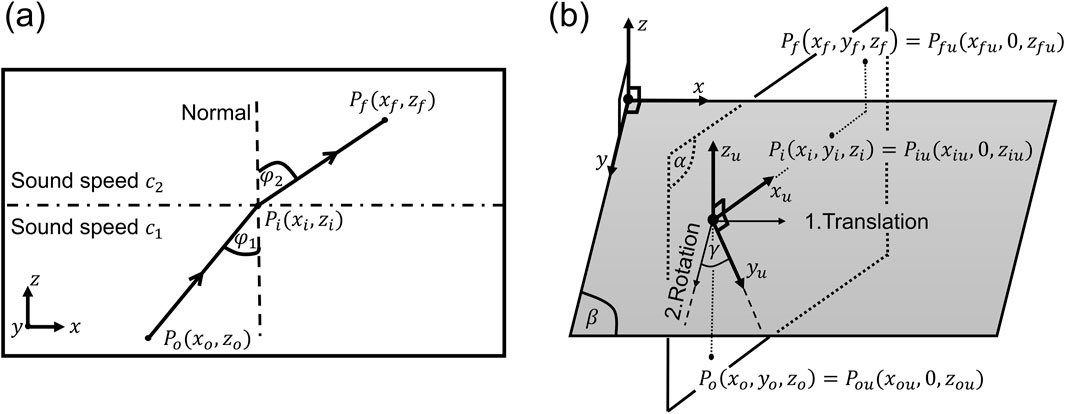
Figure 1. Refraction occurs at the planar interface between two media, represented in (A) 2D space and (B) 3D space in which the coordinate system is transformed such that the points of transducer center, incident, and focus lie on the same plane.
With the coordinates of the transducer
To apply Equation 2 in a 3-D space, a coordinate transformation technique is performed, as shown in Figure 1B. In this transformation, we establish a supporting coordinate system
Here, the coordinate
2.2 Formulation of an incident point at a 3D non-planar interface
When an ultrasonic wave encounters a non-planar interface, its propagation path changes due to refraction, which is governed by Snell’s law. To accurately model and predict how the wave interacts with the interface, it is essential to understand the local geometry of the surface at the point of incidence. The tangent at the interface provides the necessary orientation to determine the angle of incidence, which is critical for applying Snell’s law and calculating the correct refraction angle (Weston et al., 2012). In the 3D space, a non-planar interface and its tangent can be described in Equation 7 and Equation 8, respectively as:
where
The generalized Snell’s law equation can then be expressed in terms of the coordinates of the transducer, the focal point, their projections onto the tangent plane, and the incident point
where the coefficients are defined in Supplementary Section S1.1 of the Supplementary Material. The calculation of the projection points of the focal and transducer’s center points are shown in Supplementary Section S1.2 of the Supplementary Material. Figure 2A demonstrates the elements involved in the calculation of the incident point at a non-planar interface.
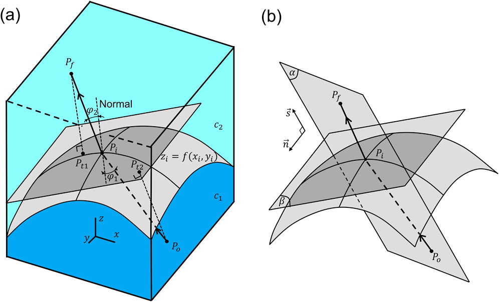
Figure 2. (A) An acoustic ray bends at the arbitrary interface
Since Equation 9 has two unknown variables (i.e.,
where
The numerical solutions of
2.3 Formulation of phase delays driving a 2D phased array
An ultrasonic phased array generates a focused beam by emitting acoustic waves from its transducers at different time instants (i.e., each transducer is driven with a specific phase delay value) such that the waves arrive at the focal point at the same time. For a homogeneous medium, the focusing algorithm used to generate the phase delays employs a constant speed of sound value of the medium to estimate the time of an acoustic wave traveling from a transducer to the focal point. In the presence of a dual-layered medium, the algorithm must account for the change in sound speed, which manifests as a change in wave direction at the interface. This directional change can only be determined when the locations of the incident points are known.
The phase delay value driving the
where
It is important to note that the equations presented in Sections 2.1–2.3 (Equations 1–11e) are employed to determine the phases of the focused beam. To formulate phases representative of a trap, the phases of the focused beam are combined with those of the trap signatures (with algorithm illustrated in Supplementary Figure S1 of Supplementary Section S2 of the Supplementary Material). These trap signature phases define specific wavefront patterns. For instance, the twin signature exhibits phase delays with
where
2.4 Theoretical basis of acoustic radiation force
The formula of acoustic radiation force was frequently used to quantify the trapping strength of acoustic tweezers on a particle (Kang and Yeh, 2010; Marzo et al., 2015). Based on Gor’kov’s formulation (Gor’kov, 1962), the radiation force
where
3 Numerical simulation
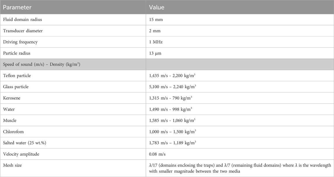
We aimed to investigate whether the incorporation of the refraction effects in phase calculations would enable the generation of more accurate acoustic tweezers through dual-layered media. Thus, we simulated the acoustic tweezers driven with the phases incorporating the refraction effects. The simulations were performed using the finite element method software COMSOL Multiphysics (v.5.3a, COMSOL AB, Stockholm, Sweden). Adapting the study by Marzo et al. (2015), we used a flat 8×8 phased array model reduced in size to be roughly comparable to that of a diagnostic array. To simplify the discussion, we assumed that the viscosity and energy absorption of the media, and deformation induced by the acoustic waves at the interface were negligible.
Figure 3 shows the model geometries employed to simulate the acoustic traps within dual-layered media divided by a planar or non-planar interface. The models were built in the 3D coordinate system with the origin located at the center of the phased array. Each transducer was represented by a circular boundary and the host media were contained within a hemispherical domain. To introduce the acoustic field into the domain, each transducer was assigned with a vibration velocity amplitude value multiplied by a term
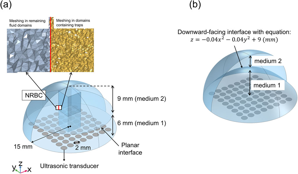
Figure 3. 3D model geometries used to simulate the acoustic traps through dual-layered media separated by (A) a planar interface or (B) a non-planar interface (e.g., downward-facing interface) – domains containing traps not shown.
For dual-layered media separated by a planar interface, the materials were selected based on the experiments that involved acoustic propagation through immiscible fluids (Bertin et al., 2012). The pairs of media under investigation were kerosene-water and chloroform-salted water. The interface was assumed to be planar when the fluids are at rest. For non-planar interfaces, the selected materials were muscle and water, motivated by the experiments of acoustically manipulating particles inside the urinary bladder of a mouse model (Ghanem et al., 2020). The parameters of the models are given in Table 1.
4 Results
In this study, we evaluated two trap configurations: twin trap and vortex trap. The results for the twin trap are discussed in detail here, while the results for the vortex trap are provided in the Supplementary Figures S2 and S3 of Supplementary Section S2 of Supplementary Material.
4.1 Acoustic tweezers in a dual-layered medium divided by a planar interface
An acoustic tweezer generated through dual layered media, under the assumption of a constant speed of sound, has a misaligned trapping point. Figure 4 demonstrates the generation and validation of an acoustic tweezer (i.e., twin trap) that accounts for the variation in the speed of sound across two media layers separated by a planar interface. In this scenario, the trap was generated through a dual-layered medium consisting of a 6 mm lower kerosene layer and a 9 mm upper water layer with an intended trapping point at 10 mm above the center of the transducer array.
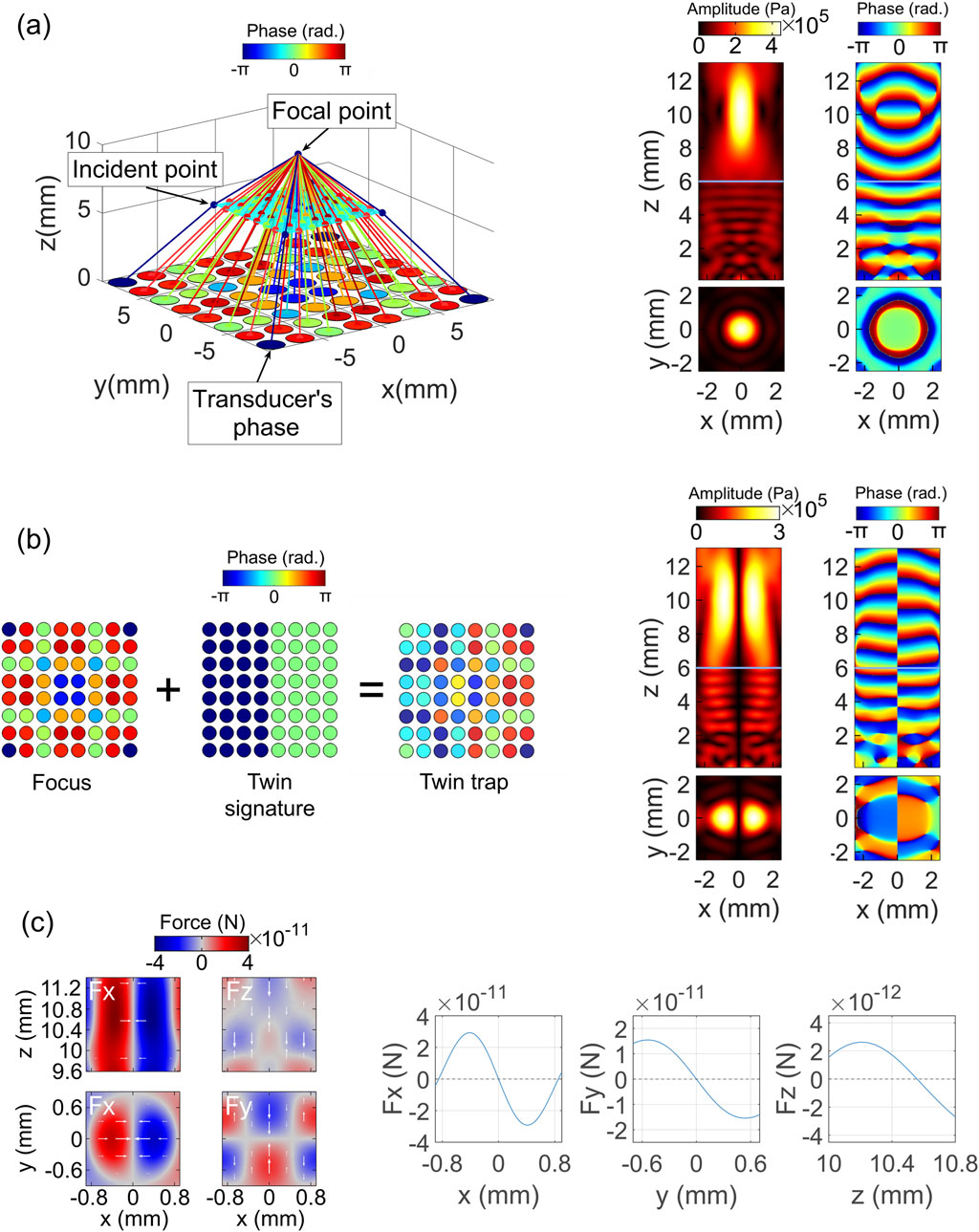
Figure 4. Generation and validation of a twin trap in a kerosene-water medium with a planar interface, accounting for the refraction effects. (A) Calculation of phases for a focused beam incorporating incident points (left), with validation using COMSOL acoustic simulations (right). The horizontal line at z = 6 mm indicates the planar interface. Shown are the pressure amplitude (top and bottom left) and pressure phase (top and bottom right), with views from the front (x-z plane at y = 0 mm, first row) and top (x-y plane at z = 10 mm, second row). (B) Calculation of phases for the twin trap (left), with validation through COMSOL acoustic simulations (right). The horizontal line at z = 6 mm marks the planar interface. Displayed are the pressure amplitude (top and bottom left) and pressure phase (top and bottom right), with front (x-z plane at y = 0 mm, first row) and top (x-y plane at z = 10 mm, second row) views. (C) Computation of acoustic radiation forces for the twin trap, showing force fields (left) and cross-sections (right).
To form the twin trap, it requires the phases of the focused beam and the phases of the twin signature. The phases of the focused beam accounting for the refraction effects at the media interface were obtained using the proposed formulation described in Section 2.1–Section 2.3. Figure 4A (left) illustrates the focal point and the phase delays of the transducers. To test the obtained phases, we simulated a transducer array driven by these phases and examined the resulting pressure fields.
As shown in Figure 4A (right), the focused beam achieves an accurate focal point (i.e., the point with the largest amplitude) located around 10 mm above the middle location of the transducer array (x = y = 0).
Figure 4B (left) presents the transducer-driving phase maps for both the focused beam and the twin signature, which are used to synthesize the overall transducer-driving phase map of the twin trap. As expected, the trapping point of the twin trap is at the same location as the focal point but on the zero-pressure amplitude and indeterminant phase axes, as shown in Figure 4B (right).
Figure 4C shows the distribution and cross-section data of the acoustic radiation forces of the twin trap exerted on a 13 μm teflon particle. The particle is suspended at the middle of the trap (i.e., x = y = 0) due to the inward loading of the horizontal (Fx) and depth (Fy) components of the acoustic radiation force, and at a vertical location of approximately 10.5 mm due to the vertical component of the force (Fz).
4.2 Acoustic tweezers in a dual-layered medium divided by a non-planar interface
In this section, we used the phases incorporating the incident points to generate a twin trap targeting a trapping location at 10 mm above the center of the phased array through dual-layered media comprising muscle and water layers, prevalent in living bodies. Considering the non-planar nature of the interfaces within these media, we defined an ideal case of a downward-facing interface (with the other interfaces illustrated in Supplementary Figure S4 of Supplementary Section S2 of the Supplementary Material).
Figure 5A (left) shows the estimated transducer-driving phases that account for the refraction effects at the muscle-water interface to generate a focused beam with an intended focal point at 10 mm above the center of the phased array. As shown in Figure 5A (right), the simulated focused beam generated with these phases achieves an observed focal point closely matching the intended location. Consequently, the trapping point of the twin trap established with this focused beam also aligns closely with the targeted trapping location at 10 mm.
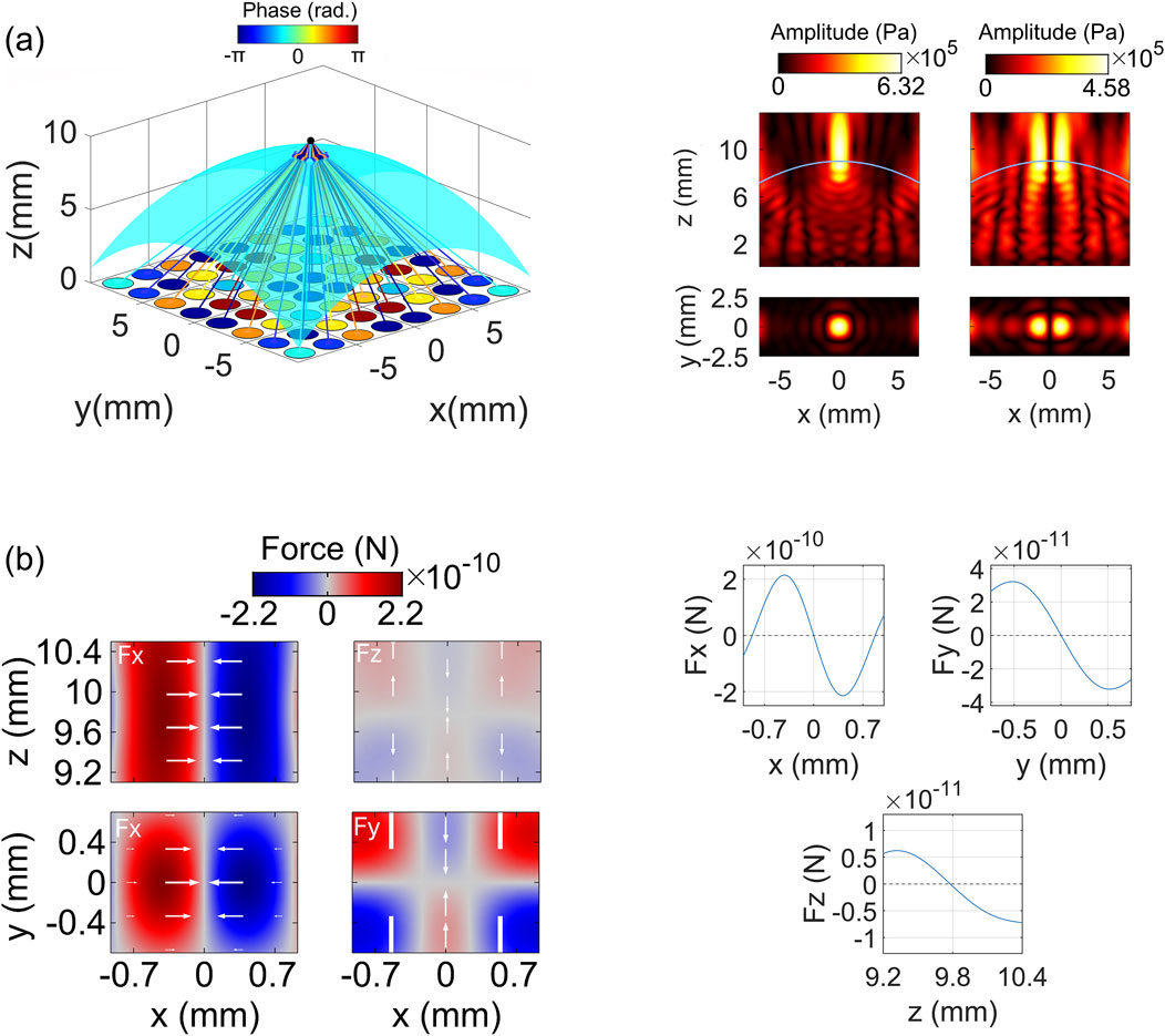
Figure 5. Generation and validation of a twin trap in a muscle-water medium with a downward-facing interface, accounting for the refraction effects. (A) Calculation of phases for a focused beam incorporating incident points (left), with validation using simulations (right). Shown are the pressure amplitude, with views from the front (x-z plane at y = 0 mm, first row) and top (x-y plane at z = 10 mm, second row). (B) Computation of acoustic radiation forces for the twin trap, showing force fields (left) and cross-sections (right). Arrows indicate the direction of forces, with their lengths representing the force magnitudes.
As can be seen from Figure 5B, the twin trap can effectively trap a 13 μm glass particle. The particle was trapped with horizontal and depth components peaked at 215 piconewtons (pN) and 32.3 piconewtons (pN), respectively. In the vertical direction, the trap suspended the particle at a height of 9.75 mm.
4.3 Comparison between acoustic tweezers generated with and without accounting for refraction phenomenon
In this section, we compare the acoustic traps generated with and without considering the refraction effects. Our primary focus is on the acoustic traps; therefore, we report the impact of considering refraction on the focused beams—one of the two elements required to form the traps—only for the case of dual-layered media divided by a planar interface, using it as an example. For the non-planar interface case, we discuss only the results related to the acoustic traps.
In the dual-layered media divided by a planar interface, the bottom layer was chloroform, while the top layer was 25 wt.% salted water.
Figure 6A (left) shows the acoustic rays propagating from the transducers to the incident points at the media interface, located at 6 mm above the phased array, and then continuing to the intended focal point at 10 mm. Notably, the acoustic rays significantly change their directions at the interface due to the moderate difference between the two media (i.e.,
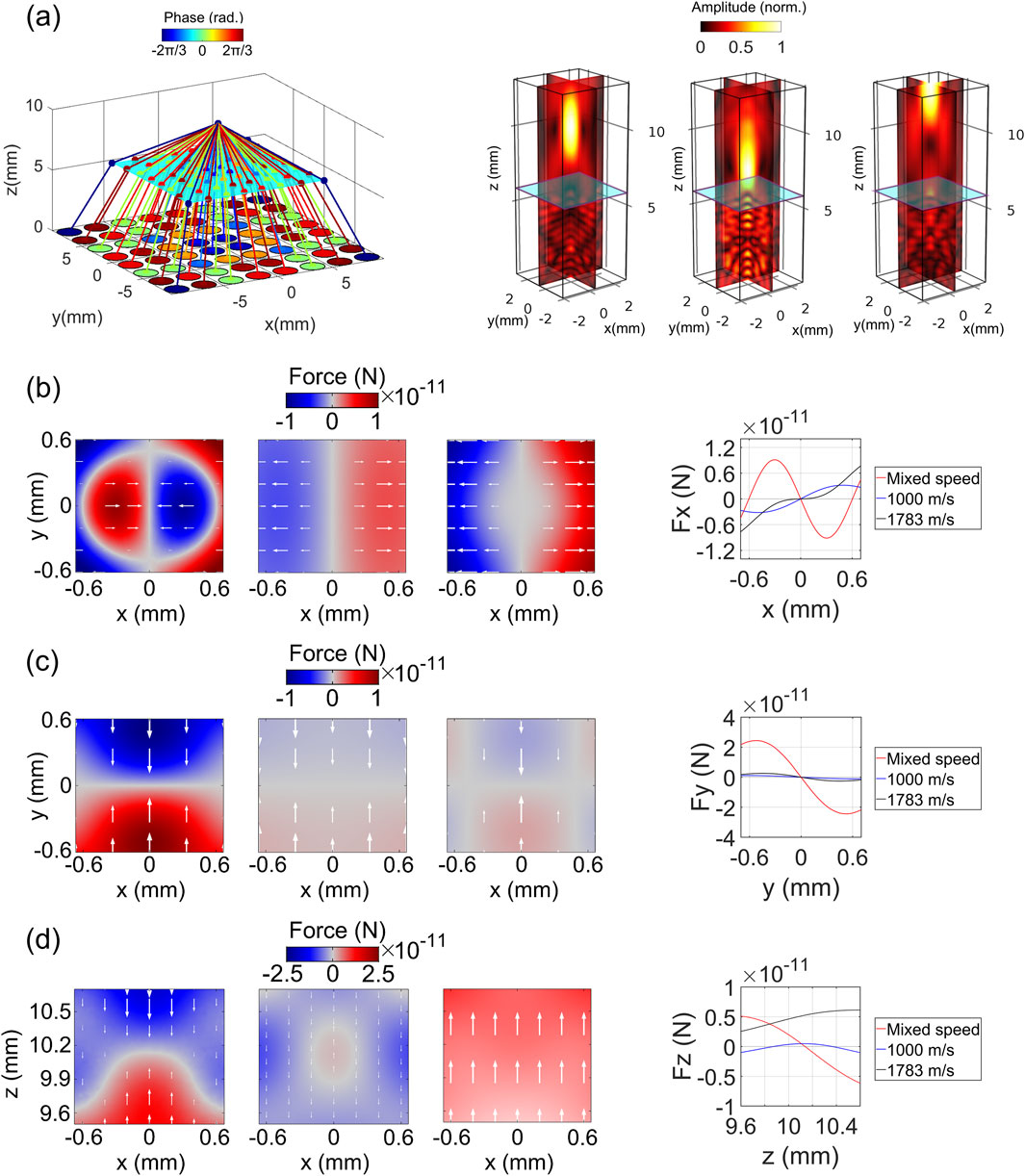
Figure 6. Analysis of acoustic beams generated with and without accounting for refraction effects through a planar interface. (A) Pathways of acoustic rays traveling from transducers to the focal point (left), and comparison of the focused beams generated with and without considering refraction (right). Normalized pressure amplitude of focused beams: with mixed speed (left), assuming homogeneity with a sound speed of 1,000 m/s (middle), and 1,783 m/s (right). (B) Horizontal acoustic radiation force (Fx) of twin traps: force distribution (left) and cross-sections (right). Force distribution is shown for refraction-corrected conditions (left), and under homogeneity assumptions with sound speeds of 1,000 m/s (middle) and 1,783 m/s (right). (C) Depth acoustic radiation force (Fy) of twin traps: force distribution (left) and cross-sections (right), comparing refraction-corrected conditions (left) with homogeneity assumptions at sound speeds of 1,000 m/s (middle) and 1,783 m/s (right). (D) Vertical acoustic radiation force (Fz) of twin traps: force distribution (left) and cross-sections (right), comparing refraction-corrected conditions (left) with homogeneity assumptions at sound speeds of 1,000 m/s (middle) and 1,783 m/s (right).
Figure 6A (right) illustrates the pressure amplitudes of the focused beams, comparing scenarios with and without accounting for the refraction effects. In the former case, the focused beam was generated using the phases that consider the incident points, a method referred to as “mixed speed”. Conversely, in the latter cases, the focused beams were generated using the phases under the assumption that the host fluids are homogeneous, meaning both layers of the media are identical (i.e., chloroform-chloroform or 25 wt.% salted water - 25 wt.% salted water). This approach is labeled as “1,000 m/s” for chloroform, corresponding to its speed of sound, and “1,783 m/s” for 25 wt.% salted water, corresponding to its speed of sound. The focal point of the focused beam generated using the “mixed speed” approach is located at 10.25 mm. In contrast, the focal points for beams with speeds of 1,000 m/s and 1,783 m/s are located at 7.55 mm and 13.2 mm, respectively, which are below and above the desired location. At the intended focal point location (i.e., 10 mm), the sound intensity for the mixed speed case is 7.32 W/cm2, whereas the intensities for the 1,000 m/s and 1,783 m/s cases are significantly lower, at 1.15 W/cm2 and 0.67 W/cm2, respectively, indicating a poor focus at this location. However, at their respective observed focal point (i.e., the point with the highest intensity along the focal line: 10.25 mm for mixed speed, 7.55 mm for 1,000 m/s, and 13.2 mm for 1,783 m/s), the intensities are 7.43 W/cm2 for the mixed speed case, 2.84 W/cm2 for the 1,000 m/s case, and 8.85 W/cm2 for the 1,783 m/s case.
The distribution of the horizontal force component exerted by the twin traps, generated from the focused beams, on a 13 μm teflon particle is shown in Figure 6B (left). The twin trap established with the consideration of the refraction effects has an oval-shaped force field divided into two regions with opposite magnitudes, separated by a central zero-magnitude area. The force vectors from these regions converge towards the center, indicating the trap’s holding capability. Conversely, the traps generated without considering the refraction effects have a rectangular-shaped force field also divided into two regions of opposite magnitudes, with a central zero-magnitude area. However, for these traps, the force vectors diverge from the center, expelling the particle from the trapping point. Figure 6B (right) illustrates the horizontal forces of the traps along y = 0. The maximum trapping force, of the trap established with the consideration of the refraction effects is 9.1 pN. In contrast, the peak expulsive forces for the traps generated with the sound speeds of 1,000 m/s and 1,783 m/s are 3.2 pN and 7.8 pN, respectively. The measurements were taken within ± 0.7 mm of x = 0. The differences in the forces may arise from the contrast in speed of sound between the teflon particle and the surrounding medium, which influences the monopole term
The depth force component in all cases drove the particle toward the trapping axis. However, the magnitude of the force exerted by the trap with the refraction effects is significantly larger (i.e., 10 times) than those exerted by the traps without the refraction effects (Figure 6B).
Figure 6D (left) shows the fields of the vertical component of the force. The trap corresponding to the mixed speed approach has a distinct separation between two regions of opposite magnitudes. The force vectors arising from these regions converge at a zero-magnitude region. The trap generated with 1,000 m/s has a much less profound distinction between low and high force values. Nonetheless, there is still a sign of force convergence at 10.4 mm. The force vectors of the trap generated with 1,783 m/s direct upward, indicating its inability to trap the particle. Figure 6D (right) further shows the forces of these cases along the trapping axis. Specifically, both the trap considering the refraction effect and the trap generated with the sound speed of 1,000 m/s can hold the particle near the designated height (y = 10 mm). However, the trapping point for the trap considering the refraction effect is slightly closer to the designated height compared to the trap with 1,000 m/s (10.15 mm vs 10.4 mm). Additionally, the trapping force of the trap considering the refraction effect is significantly stronger, being ten times greater than that of the trap generated with 1,000 m/s, as measured within ± 0.2 mm of the observed trapping points.
For the dual-layered media separated by a non-planar, downward-facing interface, we selected muscle (lower layer) and water (upper layer) as the host media. Figure 7 shows the trapping forces exerted on glass spheres by three twin traps: one generated with the refraction effects considered (i.e., mixed speed method), and two generated without considering the refraction, assuming homogeneity, with sound speed values of 1,585 m/s (for muscle) and 1,490 m/s (for water), respectively.
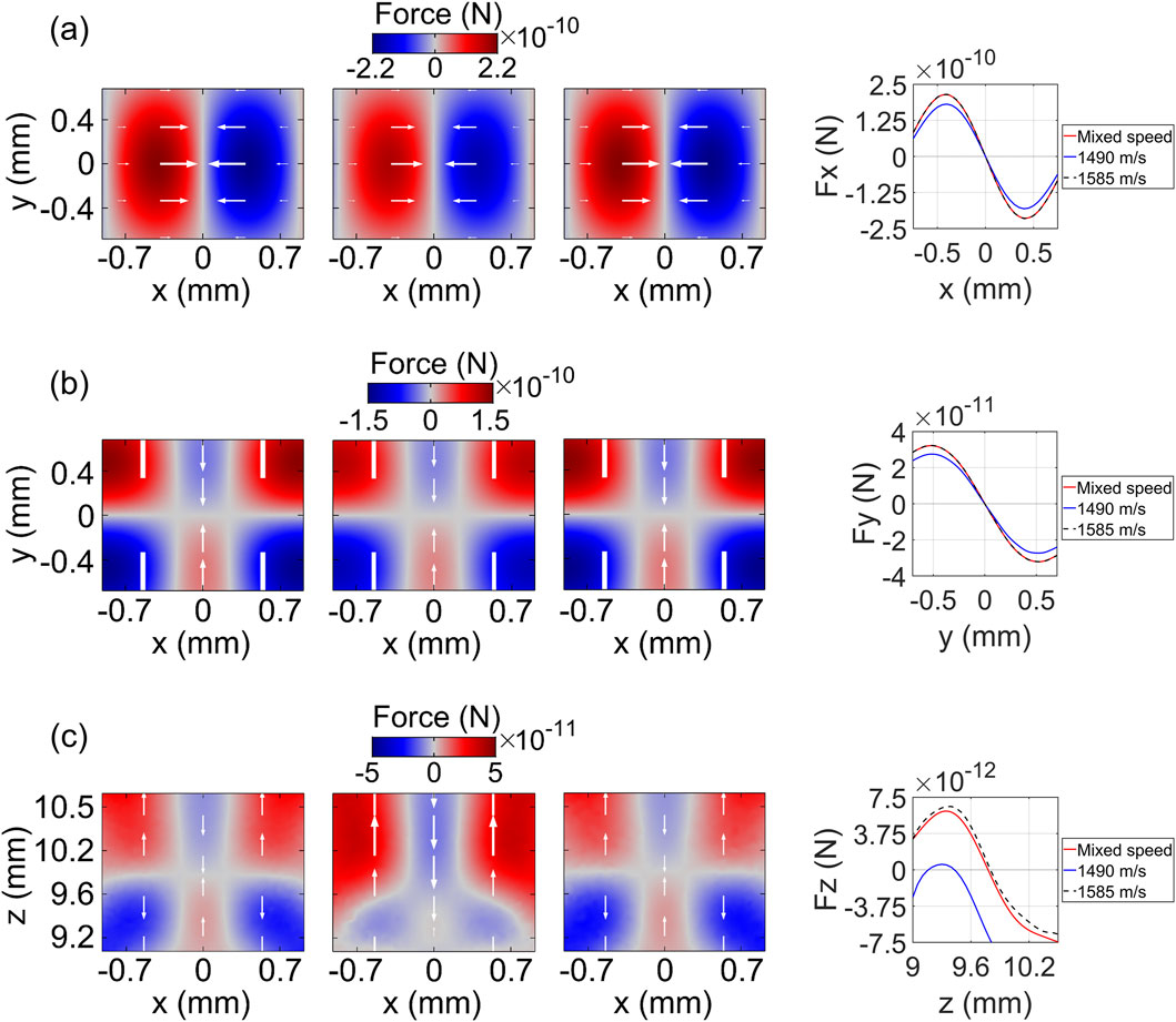
Figure 7. Analysis of acoustic beams generated with and without accounting for refraction effects through a downward-facing interface. (A) Horizontal acoustic radiation force (Fx) of twin traps: force distribution (left) and cross-sections (right). Force distribution is shown for refraction-corrected conditions (left), and under homogeneity assumptions with sound speeds of 1,490 m/s (middle) and 1,585 m/s (right). (B) Depth acoustic radiation force (Fy) of twin traps: force distribution (left) and cross-sections (right), comparing refraction-corrected conditions (left) with homogeneity assumptions at sound speeds of 1,490 m/s (middle) and 1,585 m/s (right). (C) Vertical acoustic radiation force (Fz) of twin traps: force distribution (left) and cross-sections (right), comparing refraction-corrected conditions (left) with homogeneity assumptions at sound speeds of 1,490 m/s (middle) and 1,585 m/s (right).
While the horizontal trapping forces of all three traps can successfully suspend the particle, the trap that accounts for the refraction effects exhibits a maximum trapping force of 215 pN, which is stronger than or equal to those generated without refraction correction (181 pN for 1,490 m/s and 215 pN for 1,585 m/s) (Figure 7A). Similarly, in the depth direction, the traps successfully capture the particle, with the refraction-corrected trap showing a maximum trapping force of 32.3 pN, outperforming or matching the forces of the uncorrected traps (27.5 pN for 1,490 m/s and 32.3 pN for 1,585 m/s) (Figure 7B).
In the vertical direction, the traps generated considering the refraction effects or the sound speed of 1,585 m/s can trap the particle closer to the designated height (approximately 9.8 mm) compared to the trap with the sound speed of 1,490 m/s (approximately 9.4 mm), as shown in Figure 7C. Additionally, for the former cases, the trapping forces from both sides of the trapping point are balanced, with a maximum value of around 6 pN. In contrast, for the latter case, the trapping force profile is unbalanced across the trapping point, with a maximum upward force of 1 pN and a maximum downward force of 6 pN, indicating inefficient trapping capability. Note that the measurements were taken within ± 0.5 mm of the observed trapping points.
5 Discussion
In this paper, we have proposed an approach to generate more accurate and stable hollow-focal acoustic tweezers through dual-layered media with either planar or non-planar interfaces. This was done by incorporating the incident points at the interface, obtained by applying the generalized Snell’s law of refraction, into the calculation of phase delays used to drive an ultrasonic array.
The proposed method resulted in a substantial improvement in the accuracy of the trapping point locations (coinciding with focal point locations), with trapping points located approximately at the desired position of 10 mm in both planar and downward-facing interfaces, the latter of which is defined by the equation
When evaluating the force control in the planar interface scenario, we observed a significant difference between traps generated with and without considering the refraction effects. In the horizontal direction, only the trap generated with refraction correction exhibited effective trapping capabilities, with force vectors converging towards the trapping center. In contrast, the traps generated without considering refraction not only failed to trap the particle but actively expelled it from the intended trapping point. This highlights the importance of considering the refraction effects for precise force control and effective particle trapping.
For the non-planar, downward-facing interface, the maximum horizontal trapping force of the trap that accounts for the refraction effects was 215 pN, which either exceeded or matched the performance of traps generated without refraction correction (181 pN for 1,490 m/s and 215 pN for 1,585 m/s), representing up to a 19% improvement. In the depth direction, the refraction-corrected trap outperformed or matched the forces of the uncorrected traps with a maximum force of 32.3 pN compared to 27.5 pN for 1,490 m/s and 32.3 pN for 1,585 m/s, reflecting up to a 17% enhancement in force application. In the vertical direction, the traps with the refraction effects considered or the uniform sound speed of 1,585 m/s can trap the particle closer to the desired height, with an error of only 2% (9.8 mm) compared to a 6% error (9.4 mm) for the trap using 1,490 m/s. Additionally, the trap in the latter case may fail to securely hold the particle due to the imbalanced vertical force profile, which shows a 6-fold difference across the trapping point.
The limitations of the present work include the consideration of only two media layers and the omission of complex properties such as attenuation. In practical in vitro and in vivo conditions, acoustic tweezers are often used in systems with multiple media layers or uneven interfaces, which can lead to multiple scattering as waves travel through the layers. The interaction of acoustic waves at these interfaces, resulting in continuous transformations between refracted and reflected waves, could reduce trapping efficiency. However, as shown in this study, the trapping performance of hollow-focal acoustic tweezers is primarily governed by the accuracy of the focal point, which is significantly improved by the direction of refracted waves rather than by reflected waves and their subsequent interactions. Therefore, the overall performance of the tweezers in multiple media layers or uneven interfaces may still be improved by employing the proposed method. Our method constrained to non-attenuating media. However, biological tissues cause inherent attenuation of acoustic waves, which can influence the efficiency of the acoustic tweezers. Future studies considering the impact of wave attenuation in the models would enhance the relevance of the study for practical in vivo applications. Our study also only considered longitudinal waves, and future research will examine the impact of transverse waves, which occur in solids, on the resolution and accuracy of active phase delays.
Our study highlights the critical role of incorporating refraction effects in phase calculations to create robust acoustic traps. The results indicate that the effective speed of sound is strongly influenced by the characteristics of the host media, and using refraction-corrected phases in dual-layered media offers a rapid and efficient approach for trap generation. Most importantly, our proposed method is adaptable to non-planar interfaces of varying geometries, which are often encountered in biological environments. This adaptability arises from the fact that the formation of robust acoustic traps in layered media depends solely on the trajectories of acoustic waves emitted from the transducers to the trapping point, calculated using the generalized Snell’s law. Although the specific trajectories may vary depending on the geometry of the interface, the underlying approach, which corrects for refraction effects, remains consistent, ensuring robust acoustic trap formation regardless of interface shape. The proposed method uses geometric principles and minimal information about the media involved (e.g., speed of sound, media interface geometries) to enhance the trapping performance of acoustic tweezers. This may reduce the need for extensive sensor deployment and complex post-processing, which are often required in time-reversal methods (Fink, 1992; Tanter et al., 2001). In future work, a comparison with the homogeneous assumption method, utilizing an averaged speed of sound value derived from the layered medium, would be valuable. This approach, which typically estimates tissue variation at around 1,540 m/s, is widely accepted and commonly used in ultrasonic imaging.
6 Conclusion
This study presents a new method for enhancing the accuracy and strength of acoustic tweezers in layered media. By incorporating the refraction effects at both planar and non-planar interfaces using generalized Snell’s law, we demonstrated a significant improvement in the precision of the acoustic trapping process. The results from our simulations indicate that the proposed method can maintain consistent trapping patterns and achieve up to ten times greater trapping force compared to the method that assumes a uniform speed of sound. These findings suggest that our approach has the potential to greatly expand the applicability of acoustic tweezers in complex environments, particularly in biomedical applications where multiple media layers are common. Future work will focus on experimental validation and extending the method to more complex, multi-layered media for broader biomedical applications.
Data availability statement
The original contributions presented in the study are included in the article/Supplementary Material. Further inquiries can be directed to the corresponding author.
Author contributions
HP: Conceptualization, Investigation, Formal analysis, Visualization, Writing–original draft, Writing–review and editing. NN: Investigation, Supervision, Writing–original draft, Writing–review and editing. QT: Investigation, Supervision, Visualization, Writing–original draft, Writing–review and editing. TBL: Supervision, Writing–original draft, Writing–review and editing. TQL: Conceptualization, Investigation, Visualization, Supervision, Writing–original draft, Writing–review and editing.
Funding
The author(s) declare that no financial support was received for the research, authorship, and/or publication of this article.
Acknowledgments
The authors acknowledge the use of OpenAI’s ChatGPT for language editing of this manuscript.
Conflict of interest
The authors declare that the research was conducted in the absence of any commercial or financial relationships that could be construed as a potential conflict of interest.
Publisher’s note
All claims expressed in this article are solely those of the authors and do not necessarily represent those of their affiliated organizations, or those of the publisher, the editors and the reviewers. Any product that may be evaluated in this article, or claim that may be made by its manufacturer, is not guaranteed or endorsed by the publisher.
Supplementary material
The Supplementary Material for this article can be found online at: https://www.frontiersin.org/articles/10.3389/facou.2024.1485372/full#supplementary-material
References
Aubry, J.-F., Tanter, M., Gerber, J., Thomas, J.-L., and Fink, M. (2001). Optimal focusing by spatio-temporal inverse filter. II. Experiments. Application to focusing through absorbing and reverberating media. J. Acoust. Soc. Am. 110 (1), 48–58. doi:10.1121/1.1377052
Baresch, D., and Garbin, V. (2020). Acoustic trapping of microbubbles in complex environments and controlled payload release. Proc. Natl. Acad. Sci. 117 (27), 15490–15496. doi:10.1073/pnas.2003569117
Baresch, D., Thomas, J. L., and Marchiano, R. (2016). Observation of a single-beam gradient force acoustical trap for elastic particles: acoustical tweezers. Phys. Rev. Lett. 116 (2), 024301. doi:10.1103/physrevlett.116.024301
Baudoin, M., Gerbedoen, J.-C., Riaud, A., Matar, O. B., Smagin, N., and Thomas, J.-L. (2019). Folding a focalized acoustical vortex on a flat holographic transducer: miniaturized selective acoustical tweezers. Sci. Adv. 5 (4), eaav1967. doi:10.1126/sciadv.aav1967
Bertin, N., Chraibi, H., Wunenburger, R., Delville, J.-P., and Brasselet, E. (2012). Universal morphologies of fluid interfaces deformed by the radiation pressure of acoustic or electromagnetic waves. Phys. Rev. Lett. 109 (24), 244304. doi:10.1103/physrevlett.109.244304
Clement, G., and Hynynen, K. (2002). A non-invasive method for focusing ultrasound through the human skull. Phys. Med. and Biol. 47 (8), 1219–1236. doi:10.1088/0031-9155/47/8/301
Cruza, J. F., Camacho, J., Serrano-Iribarnegaray, L., and Fritsch, C. (2013). New method for real-time dynamic focusing through interfaces. IEEE Trans. Ultrasonics, Ferroelectr. Freq. Control 60 (4), 739–751. doi:10.1109/tuffc.2013.2622
Dziewierz, J., and Gachagan, A. (2013). Correspondence: computationally efficient solution of Snell's law of refraction. IEEE Trans. ultrasonics, Ferroelectr. Freq. control 60 (6), 1256–1259. doi:10.1109/tuffc.2013.2689
Fink, M. (1992). Time reversal of ultrasonic fields—Part I: basic principles. IEEE Trans. Ultrasonics, Ferroelectr. Freq. Control 39 (5), 555–566. doi:10.1109/58.156174
Ghanem, M. A., Maxwell, A. D., Wang, Y.-N., Cunitz, B. W., Khokhlova, V. A., Sapozhnikov, O. A., et al. (2020). “Noninvasive acoustic manipulation of objects in a living body,” in Proc. Natl. Acad. Sci. 117 (29), 16848–16855.
Gor’kov, L. P. (1962). On the forces acting on a small particle in an acoustical field in an ideal fluid. Sov. Phys. Dokl. 6, 773–775.
Hefner, B. T., and Marston, P. L. (1999). An acoustical helicoidal wave transducer with applications for the alignment of ultrasonic and underwater systems. J. Acoust. Soc. Am. 106 (6), 3313–3316. doi:10.1121/1.428184
Huynh, Q. B., Pham, H. Q., Nguyen, N. T., Le, T. Q., and Van Toi, V. (2020). “Modeling of Acoustic Tweezers for the Manipulation in Biological Media,” in 7th International Conference on the Development of Biomedical Engineering in Vietnam (BME7) Translational Health Science and Technology for Developing Countries. Springer.
Kang, S. T., and Yeh, C. K. (2010). Potential-well model in acoustic tweezers. IEEE Trans. Ultrasonics, Ferroelectr. Freq. Control 57 (6), 1451–1459. doi:10.1109/tuffc.2010.1564
Marzo, A., Corkett, T., and Drinkwater, B. W. (2017). Ultraino: an open phased-array system for narrowband airborne ultrasound transmission. IEEE Trans. Ultrasonics, Ferroelectr. Freq. Control 65 (1), 102–111. doi:10.1109/tuffc.2017.2769399
Marzo, A., Seah, S. A., Drinkwater, B. W., Sahoo, D. R., Long, B., and Subramanian, S. (2015). Holographic acoustic elements for manipulation of levitated objects. Nat. Commun. 6, 8661. doi:10.1038/ncomms9661
Tanter, M., Aubry, J. F., Gerber, J., Thomas, J. L., and Fink, M. (2001). Optimal focusing by spatio-temporal inverse filter. I. Basic principles. J. Acoust. Soc. Am. 110 (1), 37–47. doi:10.1121/1.1377051
Weston, M., Mudge, P., Davis, C., and Peyton, A. (2012). Time efficient auto-focussing algorithms for ultrasonic inspection of dual-layered media using Full Matrix Capture. NDT E Int. 47, 43–50. doi:10.1016/j.ndteint.2011.10.006
Yang, Y., Ma, T., Zhang, Q., Huang, J., Hu, Q., Li, Y., et al. (2022). 3D acoustic manipulation of living cells and organisms based on 2D array. IEEE Trans. Biomed. Eng. 69 (7), 2342–2352. doi:10.1109/tbme.2022.3142774
Keywords: acoustic tweezers, layered media, acoustic aberration, Snell’s law, phase delays, ultrasonic transducers, trapping force, trapping accuracy
Citation: Pham HQ, Nguyen N, Tran Q, Le TB and Le TQ (2024) Efficient Snell’s law solution for generating robust acoustic tweezers in dual-layered media. Front. Acoust. 2:1485372. doi: 10.3389/facou.2024.1485372
Received: 23 August 2024; Accepted: 01 October 2024;
Published: 02 December 2024.
Edited by:
Yun Jing, The Pennsylvania State University (PSU), United StatesCopyright © 2024 Pham, Nguyen, Tran, Le and Le. This is an open-access article distributed under the terms of the Creative Commons Attribution License (CC BY). The use, distribution or reproduction in other forums is permitted, provided the original author(s) and the copyright owner(s) are credited and that the original publication in this journal is cited, in accordance with accepted academic practice. No use, distribution or reproduction is permitted which does not comply with these terms.
*Correspondence: Trung Q. Le, dHFsZUB1c2YuZWR1
 Huy Q. Pham
 Nhung Nguyen2
 Quang Tran
 Trung Q. Le