
94% of researchers rate our articles as excellent or good
Learn more about the work of our research integrity team to safeguard the quality of each article we publish.
Find out more
ORIGINAL RESEARCH article
Front. Therm. Eng. , 10 February 2025
Sec. Heat Engines
Volume 4 - 2024 | https://doi.org/10.3389/fther.2024.1517404
This article is part of the Research Topic Current Status, Advances, and Key Future Trends in Heat Engines View all articles
 Erick Garcia
1
Erick Garcia
1
 Vassilis Triantopoulos
1
Vassilis Triantopoulos
1 Joseph Trzaska1
 André L. Boehman
1*
André L. Boehman
1*
 Maxwell Taylor
2
Maxwell Taylor
2
 Jian Li
2
Jian Li
2
The U.S. Department of Energy Supertruck 2 program placed emphasis on development of heavy-duty trucks with high freight efficiency using commercially realizable technology suites. This paper describes the research and development process used to pursue a high thermal efficiency heavy-duty engine under Supertruck 2. The team focused on over-expanded engine cycles and advanced piston designs. This paper describes how single-cylinder engine studies using thermal barrier coated pistons, high compression pistons, and over-expanded cycles informed the development process of a multi-cylinder demonstration engine that achieved 49.9% peak thermal efficiency. While tailoring the injection strategy and other control parameters optimized the demonstration engine, more than half of the efficiency improvement came from the over-expanded cycle.
In 2023, the transportation sector accounted for 38.7% of the United States’ carbon dioxide (CO2) emissions from fossil fuel combustion (United States Energy Information Administration, 2024), and long-haul trucking was responsible for 49% of consumption of on-road diesel fuel (Walker, 2023).
In response to the large fraction of transportation energy consumption by the long-haul heavy-duty vehicle sector, the U.S. Department of Energy instituted the Supertruck program to dramatically increase the freight efficiency of heavy-duty long-haul trucks (United States Department of Energy, 2016b). The objectives of the Supertruck program included both increasing the freight efficiency of long-haul trucks (measured as ton-miles/gallon of fuel) and increasing the peak thermal efficiency of the diesel engine. Adoption of technologies explored during the Supertruck program in production heavy-duty trucks has led to billions of dollars in fuel savings for fleet operators and millions of tons of CO2 emissions avoided (United States Department of Energy, 2016a).
Supertruck 1 outlined a number of goals, including demonstration of a 50% increase in freight efficiency as compared to a 2009 baseline vehicle, achievement of a 50% brake thermal efficiency (BTE) in a new heavy-duty diesel engine, and identification of a pathway that yields a 55% BTE engine (United States Department of Energy, 2009). The Volvo Supertruck 1 team produced a demonstration vehicle meeting these targets and developed a technology pathway for a high efficiency engine, as described by O’Connor et al. (2017).
In Supertruck II, the DOE placed emphasis on “creating and enhancing technology suites that can be more cost-effective for end users to purchase and operate and places less emphasis on technology solutions with no credible pathway to cost-competitive commercial adoption in realworld applications.” Thus, in Supertruck 2, the DOE’s specific focus was on technologies that are commercially realizable and leading to high efficiency with level or reduced total cost of ownership (United States Department of Energy, 2016b).
This paper describes the research and development process used to pursue a high thermal efficiency heavy-duty engine under the Volvo Supertruck 2 program, through collaboration between the University of Michigan and Volvo Trucks. To maximize brake efficiency, the team focused on both maximizing engine cycle efficiency and minimizing parasitic losses. The team evaluated increases in compression ratio (CR), over-expanded engine cycles (i.e., Miller cycle), and piston thermal barrier coatings (TBCs) as strategies to maximize engine cycle efficiency. The systematic approach to achieving product improvements, such as improving the efficiency of heavy-duty diesel engines involves pursuing a system engineering approach with phases of innovation, development and optimization, e.g., as described by Stanton (Stanton). From a standpoint of engine thermodynamics, achieving higher thermal efficiency engines requires addressing the pathways by which thermodynamic availability is destroyed or irreversibilities are present in the engine. Combustion itself is inherently irreversible (Dunbar and Lior, 1994; Stanton, 2013).
Increases in compression ratio improve closed cycle efficiency by increasing the potential for work extraction during the expansion stroke (Stanton). To that end, researchers using Volvo piston geometries showed that a >1% thermal efficiency improvement can be achieved with a compression ratio increase (Cung et al., 2022). However, increases in compression cause increases in peak cylinder pressures and temperatures, which lead to durability concerns and higher friction loss and NOx emissions (Mohiuddin et al., 2021). These factors have typically limited the diesel compression ratios to less than 20, despite the fact that more net efficiency may be achieved at higher compression ratio (CR) (Heywood, 2018).
The team also investigated Miller cycle strategies to improve efficiency. Miller cycle refers to engine operation with a higher effective expansion ratio than compression ratio, practically achieved by early or late intake valve closing. By increasing expansion work relative to compression work, and reducing the demand for backpressure to drive exhaust gas recirculation (EGR), improved closed cycle efficiency can be achieved (De Ojeda, 2010; Vos et al., 2019). Miller cycle strategies also reduce peak cylinder pressures and temperatures, thus abating one major drawback of increasing compression ratio. However, depending on the choice of experimental constraints on air handling, reductions in efficiency have been observed with Miller cycle implementation in several cases (Wang et al., 2005; Benajes et al., 2009). Previous work by this team investigated the relationship between Miller cycle, air handling, and efficiency, considering early and late intake valve timing (EIVC and LIVC) strategies (Garcia et al., 2020), and “extreme” Miller cycle with very late LIVC valve timings (Garcia et al., 2023). It was found that, in order to improve efficiency with Miller cycle, the reduction in volumetric efficiency as IVC is delayed demands much greater turbocharger efficiencies.
Finally, thermal barrier coatings (TBC) are also considered. TBCs improve engine efficiency in principle by reducing heat transfer out of the working cylinder, and thereby increasing the enthalpy which acts on the piston during the expansion stroke. By reducing heat transfer out of the cylinder, TBCs can also abate the high heat transfer losses associated with increased compression ratios. However, much like Miller cycle strategies, TBC usage can compromise volumetric efficiency. Therefore, coatings with favorable “thermal swing” characteristics are necessary to achieve a practical efficiency benefit (Bryzik and Kamo, 1983). Durability concerns have also hampered the uptake of TBCs, since the (typically ceramic) coatings tend to flake off the piston after repeated exposure to the extreme in-cylinder environment in a diesel engine. Recent state-of-the-art TBC research has investigated porosity (Somhorst and Oevermann, 2024), bond coatings (Velusamy et al., 2024), and material layering strategies (Raja et al., 2023), all targeting improvements in efficiency and durability.
The single-cylinder engine studies of thermal barrier coated pistons, high compression pistons and over-expanded cycles informed the development process of a multi-cylinder heavy-duty diesel engine. While each of these approaches can increase efficiency independently, synergistic effects on efficiency were especially sought, with the demonstrator engine achieving 49.9% peak thermal efficiency.
The research engine used to conduct the experiments at the University of Michigan in this study is an 11 L six-cylinder Volvo MD11 heavy-duty direct injection diesel engine that has been converted into a single-cylinder research engine (SCRE) by deactivating cylinders 1–5. The original unit injector for the firing cylinder has been replaced with an electronically controlled common rail injector. The conventional camshaft-rocker valve train has been replaced with an electro-hydraulic Lotus Active Valve Train (AVT) system that allows full control over intake and exhaust valve timing, lift, and velocity (Louis, 2014).
The EGR fraction is calculated from the ratio of CO2 levels measured in the intake and exhaust streams. Engine-out soot emissions were obtained using an AVL 415 smoke meter while a Horiba MEXA ONE emissions bench was used to measure CO, CO2, O2, NOx, and THC.
An AVL Indimaster and Indicom indicating system was used as the data acquisition hardware and software, respectively, for recording high speed signals. The cylinder pressure data was obtained at a resolution of 0.1 crank angle degrees (CAD) with an AVL GH14P pressure sensor and an AVL 416 crank angle encoder. The pressure trace for each experiment was obtained from the averaged values of 200 cycles at a 2 kHz cutoff frequency.
This experimental facility has been described in detail in prior work (Garcia et al., 2020; Garcia et al., 2023; Garcia, 2021). This experimental facility enabled exploration of high IMEP combustion processes with innovative fuel injection, combustion chamber and valve timing strategies to support the Volvo Supertruck II team’s pursuit of high thermal efficiency engines.
The experimental results here are analyzed in part using energy breakdown diagrams, as in previous publications (Garcia et al., 2020; Garcia et al., 2023; Garcia, 2021). The fraction of the energy input to the cycle (i.e., fuel energy) which “flows” to the brake, friction, pumping, heat transfer, and exhaust are computed using the following equations, expressed in mean effective pressure units. In all reported data, net IMEP was experimentally fixed by tuning injection duration. Brake torque measurements are not reported, since the engine has excess friction from the five deactivated cylinders. Instead, FMEP is estimated using a Chen-Flynn friction model (Chen and Flynn, 1965), and BMEP is thus estimated as net IMEP less FMEP.
Table 1 lists the operating conditions for the nominal A75 operating point the SCRE experiments were conducted at. Tables 2, 3 describe the thermal barrier coatings and valve timing strategies considered in this study, respectively.
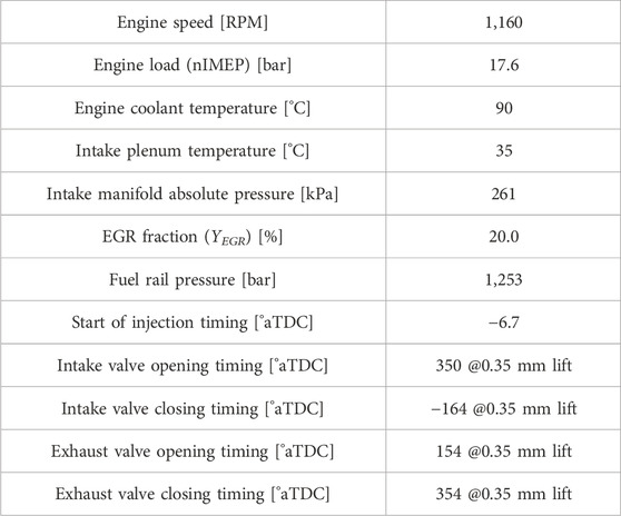
Table 1. Operating conditions for A75 operating point.
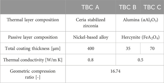
Table 2. Thermal barrier coated piston properties.
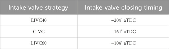
Table 3. Intake valve closing strategies.
Six-cylinder engine testing was conducted in Volvo’s Hagerstown, Maryland engine development lab using a 725 horsepower GE DC dynamometer, coriolis fuel flow measurement, two Horiba emissions benches, AVL 483 soot measurement, and an AVL X-ION indicating measurement system with six Kistler 6045A cylinder pressure sensors. Testing was also conducted at Southwest Research Institute (SwRI) in San Antonio, Texas using a 600 horsepower Midwest eddy current dynamometer, coriolis fuel flow measurement, a Horiba emissions bench, an AVL 415 smoke meter, and a National Instruments based indicating measurement system. At both Volvo and SwRI labs, 48V components were powered by a Keysight RP7945A (80 V, ±250 A, 10 kW) bi-directional power supply and current measurements were recorded in test data.
The first three sections describe laboratory scale studies with the MD11 SCRE at the University of Michigan Auto Lab. These studies were designed to inform the collaborative process undertaken by the University of Michigan and Volvo Trucks. The fourth section highlights Volvo’s development efforts for their freight efficiency optimized and BTE optimized demonstration engines.
Three thermal barrier coatings (TBCs) of varying composition and thickness listed in Table 2 were utilized in this study, in conjunction with Volvo’s wave piston design (Eismark et al., 2019; Eismark and Balthasar, 2013). The experiments were carried out at the A75 condition (described in Table 1), an operating condition representative of the medium load-low speed portion of a Class 8 truck engine’s speed-torque map.
Figure 1 displays cycle average results of 10 key engine performance metrics for the uncoated wave and the three TBC pistons examined under the A75 condition with fuel injection pulse width adjusted to fix nIMEP at 17.6 bar. Figure 1A shows the relative change in ISFC compared to the uncoated baseline wave piston at A75. The TBC A piston increased ISFC by 1.2% while the TBC C piston increased ISFC by only 0.6% at A75. The TBC B piston, however, improved ISFC by 0.2% at A75.
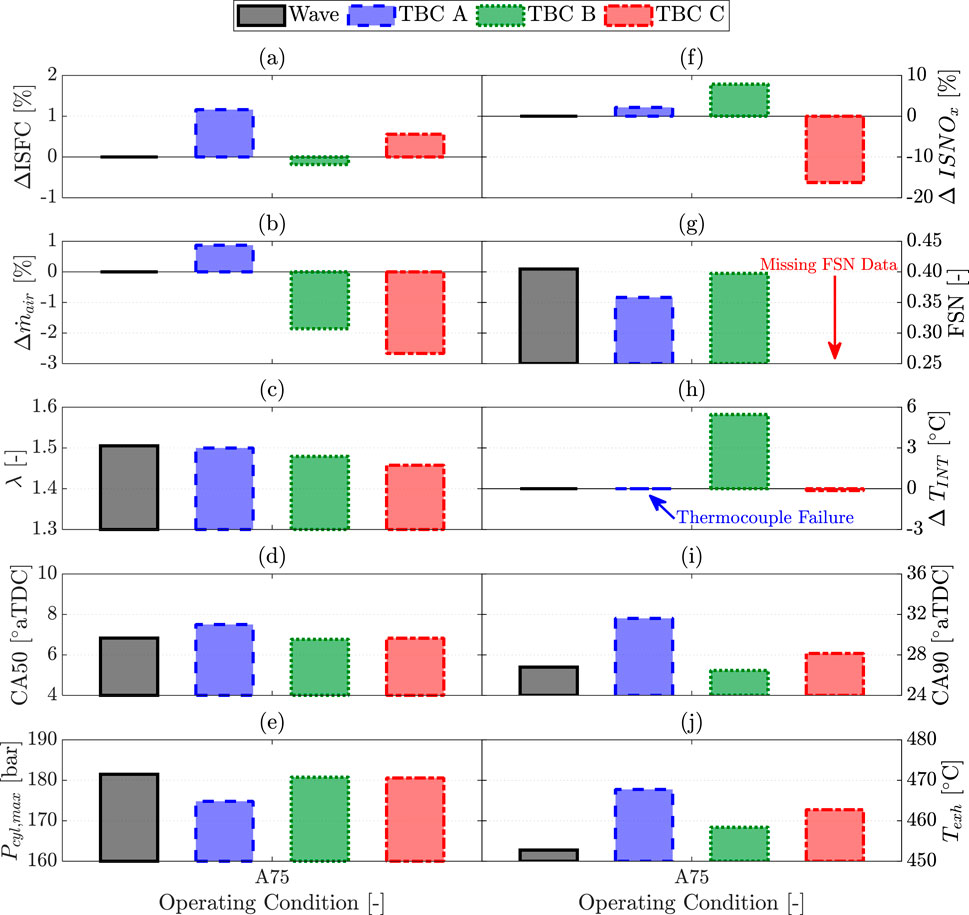
Figure 1. Cycle average results of 10 key engine performance metrics for the uncoated wave and the three TBC pistons at A75. (A) Relative change in ISFC compared to the uncoated wave piston (ΔISFC), (B) mass air flow (
TBC performance was highly dependent on volumetric efficiency, which was determined by temperature swing characteristics. Cases with volumetric efficiency penalties increased the heat transfer gradient between the combustion gasses and combustion chamber due to reduced cylinder dilution. The insulative properties of each TBC are what determined how each coating responded to the aforementioned change in heat transfer gradient, and that variable response leads to the varying results on the impact TBCs have on fuel conversion efficiency found in this study, and others (Assanis et al., 1991; Somhorst et al., 2019).
The thinner coating on the TBC B piston results in operating at ISFC parity with the baseline piston due to a minimal reduction in volumetric efficiency, keeping the increase in heat transfer gradient at a minimum. The superior insulative properties of the thicker coating on the TBC C piston fail to prevent ISFC from increasing by 0.6% because of extended combustion duration at the tested condition.
Overall, the influence of the wave piston’s bowl geometry on late soot oxidation is robust enough to prevent increased PM emissions from the TBC pistons at the tested condition. These experimental results suggest that thermal efficiency benefits from TBC pistons are best realized at engine operating conditions with higher combustion temperatures, where the insulative properties of the TBC may better minimize heat transfer losses compared to an uncoated piston.
In this section, the effects of pairing a TBC piston with Miller cycle strategies are investigated to build on the findings of Garcia et al. (2023). Miller cycle strategies require high boost to induct sufficient oxygen into the cylinder due to their inherent volumetric efficiency penalties. The experiments in this section investigate the impact of varying boost under fixed and variable turbocharger efficiencies. By using the variable turbocharger efficiency constraint, this experiment investigated the that impact NOX control via IVC modulation has on fuel conversion efficiency and identified the IVC strategy best suited for high boost applications. This section also highlights key differences between EIVC and LIVC strategies of equivalent volumetric efficiency to identify the approach best suited for Volvo’s demonstrator engine.
Each experiment uses the SCRE detailed in Section 2.1 and the A75 operating condition described in Tab1e 1. The IVC strategies are as listed in Table 3. Finally, the baseline uncoated wave piston and the TBC B piston from the previous section were each used, as this piston resulted in the greatest ISFC improvement (TBC B from Section 3.1).
The two sets of experiments conducted in this section explore the influence turbocharger efficiency has on engine performance when utilizing Miller cycle strategies. The first set of experiments highlight the fuel consumption improvement possible when leveraging the NOX emissions benefit of Miller cycle profiles and a TBC piston. For this set of experiments, the turbocharger efficiency (η TC) of the Miller cycle cases exceed that of the conventional (CIVC) case. As such, the second set of experiments analyzes all intake valve timing strategies at the same elevated η TC constraint to fairly assess their performance under elevated boost conditions.
For the first data set, all actuator settings were set as outlined in Table 1, with Y
EGR
fixed at 20% and fuel rail pressure set to 125 MPa. Fuel injection pulse width was again adjusted to match the baseline load (nIMEP = 17.6 bar). Intake manifold pressure was adjusted for each IVC strategy such that
Figure 2 provides a breakdown of the energy pathways for each IVC strategy, as described in Section 2.1, when subjected to the prescribed baseline NOX threshold. The total height of the stacked bars corresponds to the normalized fuel energy, such that the change in height of the stacked bars corresponds to a change in indicated efficiency. With the uncoated piston, LIVC60 has the optimal balance of heat transfer benefits and exhaust, pumping, and friction losses that allow for superior fuel consumption over the other cases. The heat transfer and exhaust tradeoff of the Miller cycle profiles is further improved with the TBC piston such that LIVC60 operates utilizing 2% less fuel than the baseline case. Similar levels of closed cycle efficiency improvements were observed with LIVC strategies previously (Vos et al., 2019).
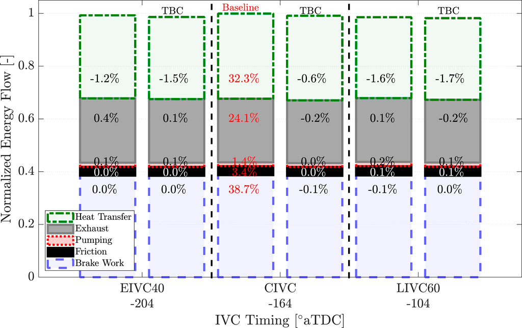
Figure 2. Normalized energy breakdown for each IVC timing strategy at
Operating at NOX parity with the Miller cycle profiles at more dilute conditions than the CIVC case is enabled by leveraging the lower peak cylinder temperatures corresponding with the reduction in effective compression as IVC is varied. Operating under much leaner conditions also allowed the Miller cycle strategies to offer superior fuel consumption over the CIVC case. However, the η TC requirement of the Miller cycle cases exceeded those of the CIVC case. Therefore, a constant η TC constraint was applied in the next experiment. For the second data set, all actuator settings were as set previously, except intake manifold pressure was adjusted such that η TC = 65.4 ± 1.1%. The intake manifold absolute pressures for each IVC strategy that met these η TC criteria were CIVC at 320 kPa, LIVC60 at 350 kPa, and EIVC40 at 340 kPa.
Figure 3 presents the total fuel energy utilized by each IVC strategy to match the baseline load, now all operating at the prescribed η TC constraint (i.e., at fixed turbocharger efficiency). Whereas in the previous data set utilizing Miller cycle profiles reduced heat transfer losses over the CIVC case, the prescribed η TC constraint counteracts that benefit due to poorer thermodynamic properties from operating at a lower air-to-fuel equivalence ratio. The EIVC40 case does not increase heat transfer losses over the CIVC case, but the LIVC60 case does. All TBC piston Miller cycle cases again decrease heat transfer losses compared to their uncoated counterpart.
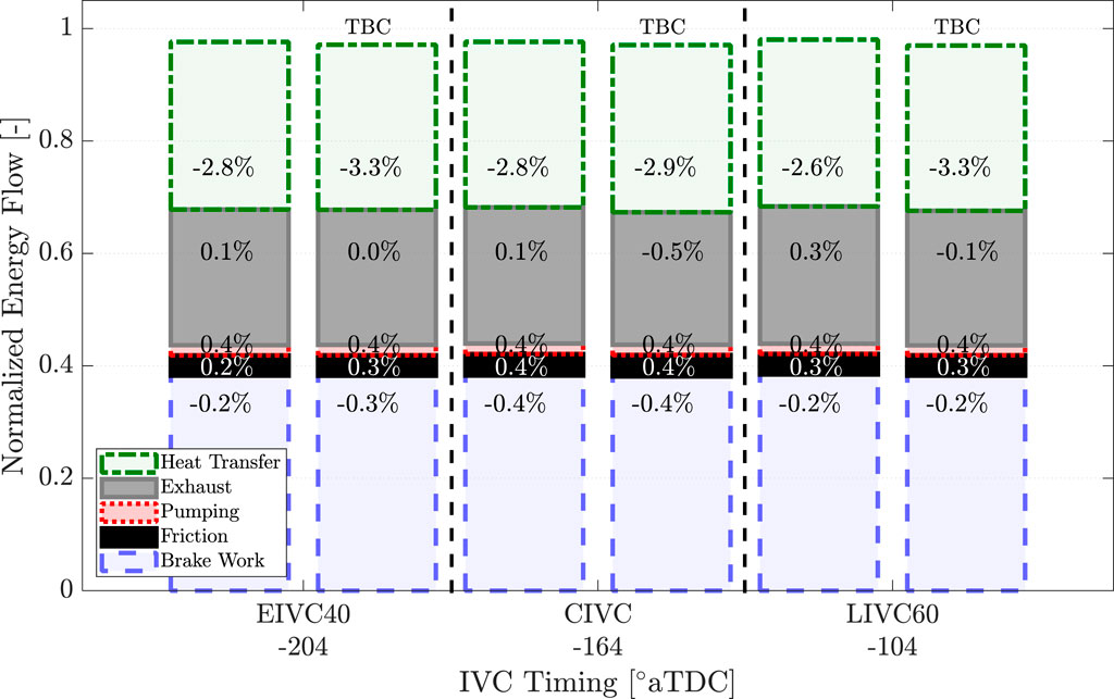
Figure 3. Normalized energy breakdown for each IVC timing strategy at η TC ≈ 65.4%. Data labels represent the percent change relative to the baseline value of that respective energy pathway.
The optimum IVC strategy under constant η TC, is EIVC40 for the uncoated piston. This optimum exists due to the tradeoff between operating at unfavorable thermodynamic properties and reducing heat transfer losses. This balance minimizes any decrease in thermal efficiency such that fuel consumption is on par with an equivalent high η TC conventional IVC case, but with 20% lower NOX emissions.
The TBC piston shifts the heat transfer and exhaust tradeoff of the Miller cycle profiles such that the optimum IVC timing becomes LIVC60, obtaining a simultaneous 0.5% BSFC and 20% NOX emissions improvement over an equivalent high η TC conventional IVC case.
While the integrity of the coating was never compromised in the SCRE testing, the conclusion of this testing campaign was too late into the development cycle of Volvo’s demonstrator engine for a proper degradation study. Thus, this TBC technology was ultimately omitted from Volvo’s demonstrator engine out of an abundance of caution pertaining to the coating’s longevity.
In addition to TBC pistons, pistons with increased compression ratio were also considered to maximize the demonstrator engine’s efficiency. To inform the choice of compression ratio for the demonstrator engine, the University of Michigan was tasked with identifying the challenges and benefits of increasing the geometric compression ratio of the MD11 SCRE. The experiments conducted in this section investigate the effects of increasing compression ratio from 16.74:1 (16.7CR) to 19:1 (19CR). In addition, the effect of achieving the same peak cylinder pressure as the 19CR piston by increasing intake manifold pressure with the 16.7CR piston is also investigated.
All actuator settings were set as outlined in Table 1. Fuel injection pulse width was adjusted to match the baseline load (nIMEP = 1.76 MPa). With the 16.7CR piston, the additional data point was recorded with intake manifold pressure increased from 261 kPa to 300 kPa, thus matching
Figure 4 shows cycle average results for 12 key engine performance metrics at the A75 operating condition when increasing the compression ratio from 16.74:1 to 19:1. Figure 4B shows that the 19CR case and boosted 16.7CR case improved nISFC by 1.8% and 1.6%, respectively, compared to the baseline case. Improvements are also reported for BSFC relative to the baseline case, but these are substantially smaller. Both the boosted 16.7CR and 19CR cases suffer from increased friction losses associated with their high peak cylinder pressures, as shown in Figure 4F.
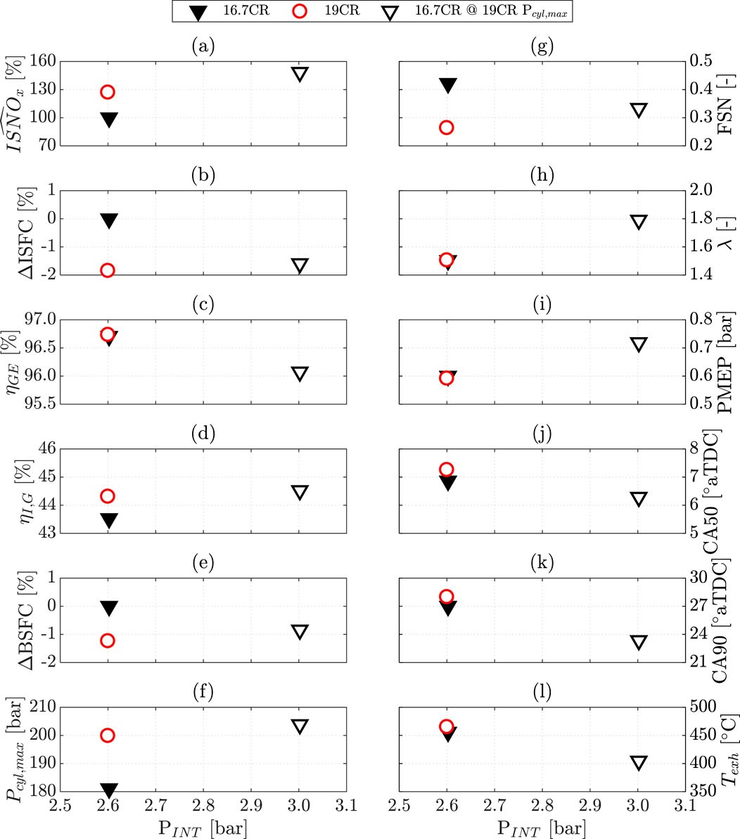
Figure 4. Cycle average results of 12 key engine performance metrics for the 16.7CR and 19CR wave pistons at the A75 operating condition, with an additional 16.7CR data point reported operating at the equivalent
Figures 4C, I show that pumping losses also increase when elevating intake manifold pressures to increase the engine’s peak cylinder pressure. For the boosted 16.7CR case, these losses reduce the fuel consumption benefit that would have resulted from advanced combustion phasing, Figures 4J, K, achieved from operating with a leaner charge. Thus, while gross indicated efficiency was maximized with the boosted 16.7CR case, net indicated and brake specific fuel consumption were minimized with the 19CR piston.
While both the 19CR and boosted 16.7CR case improve BSFC, these fuel consumption improvements come with NOx penalties. The 19CR case suffered a 27% NOX penalty over the baseline, while the boosted 16.7CR case incurred a more substantial 48% NOX penalty as shown in Figure 4A.
Altering piston design to increase compression ratio can cause volumetric efficiency penalties that result in richer operation and increase PM emissions. Despite much leaner operation, as shown in Figure 4H, the boosted 16.7CR case only decreased the FSN by 21% while the 19CR managed a 37% reduction in FSN over the baseline while operating at the baseline lambda, as shown in Figure 4G. This indicates the higher compression ratio design did not impact volumetric efficiency nor alter the late burn soot oxidation characteristics of the piston bowl.
Finally, Figure 4L shows operating the 19CR piston increases the exhaust temperature by 10°C despite the improved efficiency. On the other hand, the boosted 16.7CR case decreases exhaust temperature by 52°C. This substantial decrease in exhaust gas temperature (and therefore enthalpy) may prevent the turbocharger from producing the additional 0.4 bar of boost supplied at this operating point.
The results in Section 3.3.1 demonstrate the challenges and benefits of increasing compression ratio, with improved fuel consumption and PM emissions obtained at the expense of increased NOX emissions. It was shown that simply leveraging advances in turbocharging technologies to elevate boost pressures obtained a comparable fuel consumption benefit. However, the elevated boost pressure condition diminished the PM emission benefit and exacerbated the NOX emission penalty observed with the high CR piston. Previous literature has shown that Miller cycle applications in this SCRE platform improve engine performance over conventional valve timings at the elevated cylinder pressures resulting from high boost (Garcia, 2021). Thus, Miller cycle operation with the combination of elevated compression ratios and elevated boost was investigated further.
Given that the objective of SuperTruck is improved fuel efficiency, the decision was made to accept the NOX emissions penalty associated with increasing compression ratio as the upper limit in this phase of testing. The experiments conducted in this section investigate the pairing of EIVC and LIVC profiles with high boost levels using both the baseline 16.7CR and 19CR pistons to maximize fuel consumption improvement from increasing compression ratio without exacerbating the associated NOX emissions penalties.
For each piston and IVC timing, two sets of actuator settings (“nominal” and “optimized”) were tested. The process to select actuator settings was carefully designed to investigate key aspects of Miller cycle and high compression operation. First, the CIVC 16.7CR and 19CR cases were the baseline cases for their respective pistons, as in Section 3.3.1, where η
TC was 55% ± 1%. For each Miller cycle case with the 16.7CR piston, intake manifold pressure was varied to meet the η
TC target. NOx emissions were allowed to vary freely, as the Miller cycle operation reduced their level well below the 19CR level. For the 19CR piston Miller cycle cases, both intake manifold pressure and EGR fraction were varied to fix η
TC and match the CIVC ISNOx emissions of 4.3 ± 0.3
Different actuator settings were chosen for the optimized conditions. For the 19CR piston, η TC was increased from 55% ± 1% to 58% ± 1%, with boost and EGR fraction again tuned to meet this constraint and the ISNOx constraint. The increased η TC of 58% ± 1% was prescribed as an upper bound to match the capabilities of the state-of-the-art turbocharger systems. The optimized 16.7CR cases, on the other hand, were not constrained to a η TC target. Instead, boost was increased until the ISNOx constraint was reached with EGR fraction fixed. In this way, η TC was allowed to vary to gain an understanding of the performance needed by next-generation turbocharger systems to obtain maximum efficiency out of Miller cycle operation. All actuator settings are summarized in Table 4.
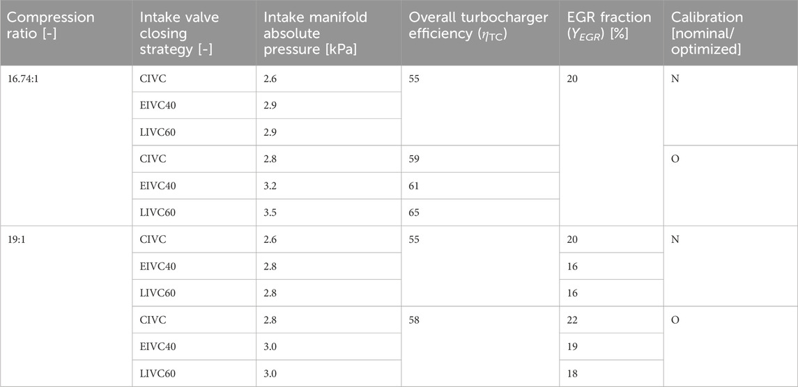
Table 4. Operating conditions for A75 operating point.
Figure 5 shows cycle average results for 10 key engine performance metrics at the A75 operating condition for the 16.7CR and 19CR pistons under the sweep of intake valve timings, with nominal and optimized actuator settings. The 16.7CR piston operating with LIVC60 under the nominal calibration yields the ideal combination for minimizing NOX emissions, as shown in Figure 5A. This benefit is achieved at the expense of the increased PM emissions shown in Figure 5F, but Figure 5G shows BSFC remains unchanged. The optimized 16.7CR piston cases were significantly diluted, as shown in Figure 5H, before reaching the prescribed NOX emission threshold of 4.3
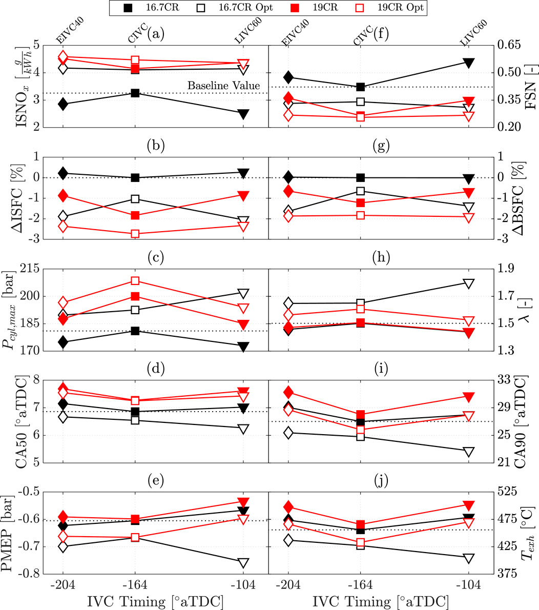
Figure 5. Cycle average results of 10 key engine performance metrics for the 16.7CR and 19CR wave pistons at the A75 operating condition, with an additional 16.7CR data point reported operating at the equivalent
Miller cycle lends itself to minimizing peak cylinder pressures that would otherwise be detrimental to efficiency increases as higher compression ratios are utilized. Furthermore, Miller cycle timings can preserve NOX emissions at baseline levels with lower EGR levels, simplifying the maintenance intervals associated with EGR systems. Finally, utilizing Miller cycle timings prevent exhaust temperatures from decreasing below baseline levels, as shown in Figure 5J. This is crucial for ensuring the optimal performance of exhaust aftertreatment systems. These key observations motivated the decision to utilize Miller cycle timings in Volvo’s demonstrator engine, the development of which is described in the following section.
The Volvo SuperTruck 2 program developed two heavy duty diesel engine specifications, referred to as the freight efficiency optimized (ST2-FE) and the BTE optimized (ST2-BTE) engines. The ST2-FE engine was developed towards integration into a lightweight, aerodynamic vehicle, requiring prioritization of compact dimensions, lightweight, and drivability in addition to fuel consumption; the Volvo D11 engine was selected as the basis for this specification. The ST2-BTE engine specification was developed as a test-cell only demonstrator, enabling hardware selection prioritizing BTE without specific requirements for vehicle integration or drivability; the Volvo D13TC with its integrated turbocompound system was selected as the basis for this engine.
The overexpansion concept demonstrated by the University of Michigan, combining a high geometric compression ratio with Miller inlet valve timing and an efficient turbo system, was identified as a foundational concept for both ST2 engine specifications. Simulations were used to reduce the scope of physical testing. These 1-D engine and powertrain simulations used GT-Power (Gamma Technologies) to model components and configurations. An EGR Pump component was added to both the 11L ST2-FE and 13L ST2-BTE models. 1-D DOE evaluations varied engine calibration against hardware variations of Miller IVC timing, piston compression ratio, turbine and compressor sizing. An example evaluation of the ST2-FE engine is shown in Figure 6, the ST2-BTE engine is shown in Figure 7.
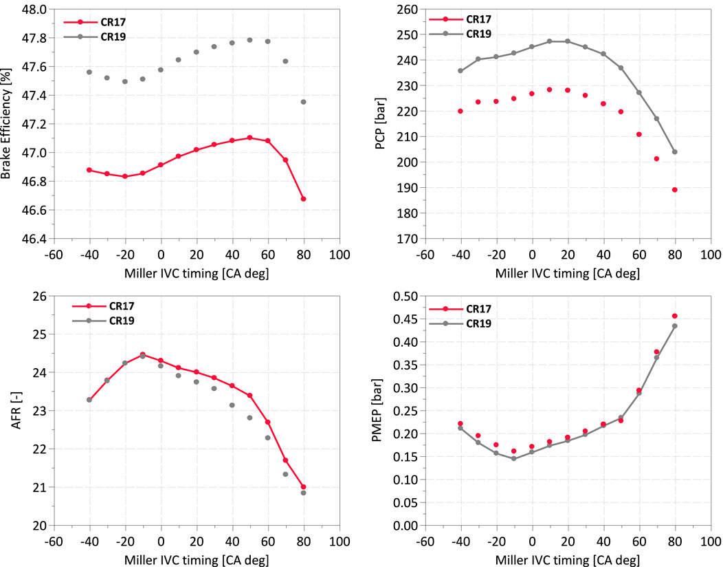
Figure 6. Example simulation result for ST2-FE 11L EGR Pump engine, showing effect of Miller cam specification and compression ratio on engine performance. For each point, engine calibration and scaling of turbomachinery are also optimized.

Figure 7. 1-D simulation DOE optimization result example for ST2-BTE engine evaluating three compression ratio specifications as a function of camshaft profile, sizing of turbo compressor, high-pressure turbine, and low pressure turbine.
Starting with a Volvo 11L engine platform, a test campaign was executed to define the ST2-FE combustion system specifications, summarized in Figure 8.
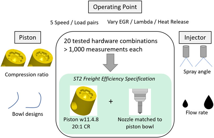
Figure 8. Summary of test campaign for selection of 11L ST2-FE in-cylinder combustion hardware.
Several variations of Volvo’s wave piston concept, which utilizes dividing features to enhance the interactions between sprays, were evaluated in CFD with compression ratios within the suggested range from earlier 1-D simulations and single cylinder testing.
The prototype pistons were tested on a mule engine in a campaign utilizing Design of Experiments methods to characterize the performance of each bowl using a reference injector specification. Alternative fuel injector nozzles were tested, varying flow rate and spray angle.
The test campaign led to the selection of a high compression ratio bowl design with a moderate injector nozzle specification. In this test, the fuel consumption benefits 20:1 compression ratio were moderate relative to designs with lower compression ratio, however simulation indicated that 20:1 was the favorable path for integration with the intended combination of EGR Pump, high performance turbo, and Miller camshaft – some of the frictional and cylinder pressure challenges introduced by the high CR would be relieved and the system would enjoy the benefits of high expansion ratio.
The 11L basis engine was updated with a EGR Pump, a 48V powered positive displacement pump produced by Eaton. The variable geometry turbocharger (VGT) was replaced with a high efficiency fixed geometry turbocharger (FGT) with a pulse-utilizing double-inlet design, with initial housings sized based on 1-D simulation. Figure 9 highlights the primary updates to the system. Photos of the configuration are shown in Figure 10.
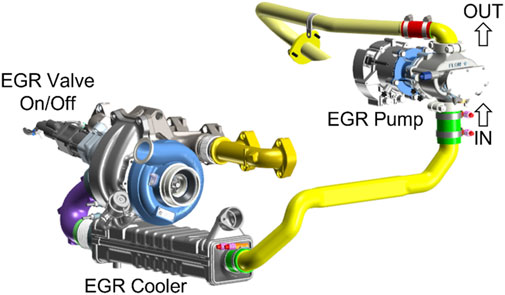
Figure 9. High efficiency turbocharger and 48V EGR Pump applied to exhaust circuit of ST2-FE engine.
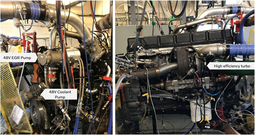
Figure 10. FE engine test cell installation, highlighting Eaton 48V EGR Pump mounted on cold side of engine, high efficiency turbocharger on hot side of engine.
The efficient turbocharger coupled with EGR Pump enabled the engine to maintain the BSNOx level of the reference 11L while operating at an elevated air-fuel-ratio (AFR), improving gross indicated thermal efficiency by shorter combustion durations and reduced in-cylinder heat losses. The faster heat release rate did increase engine-out NOx emissions, requiring increased EGR flow to maintain NOx parity with VGT reference. Despite elevated EGR requirement, FGT with EGR Pump improved engine open-cycle efficiency (OCE). The result of these improvements to pumping and combustion performance was an increase of ∼1.2% BTE points.
The previously selected piston and injector package was applied, and turbine trim adjustments were evaluated to balance the increase in peak cylinder pressure. The increased compression ratio and bowl updates improved gross Indicated Thermal Efficiency (gITE) and resulted in a significant improvement of 0.76% BTE at the max efficiency engine operating point. However, a larger turbine trim and some wastegate flow at high load was necessary to control peak cylinder pressure within engine design limits. This compromise to turbo system efficiency coupled with higher FMEP losses moderated the efficiency increase to +0.3%BTE points at full load. This compromise was anticipated in this step, as the high compression ratio was intended to be paired with a Miller camshaft to fulfill the overexpansion strategy.
Three Miller camshafts, designed based on University of Michigan testing and 1-D simulation, were produced as described by Figure 11.
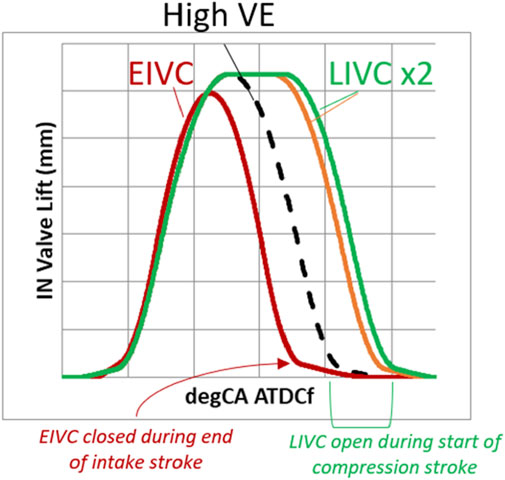
Figure 11. Reference and Miller camshaft profiles tested on ST2-FE engine.
The EIVC camshaft worked well on the ST2-FE engine, enabling a smaller turbine trim to be restored and reduced wastegate requirement at high load. Open cycle efficiency improved and charge temperature at start-of-combustion was reduced by moving compression work from the piston to the turbocharger and charge-air-cooler, thus requiring a lower EGR fraction to meet a target BSNOx value. The EIVC cam package delivered 0.34% BTE. The LIVC camshaft allowed further VE control without reducing valvelift or violating valvetrain kinematic requirements, and produced an additional 0.28% BTE.
An additional development step improved efficiency throughout the engine operating range through reduction of parasitic losses, improved charge cooling, and reduced exhaust backpressure; these improvements were not as impactful at the max efficiency operating point, where the delta was a minor 0.20% BTE.
The ST2-FE hardware selection process is represented in Figure 12. The progress in efficiency culminating in a 2.79% BTE improvement is plotted in Figure 13.
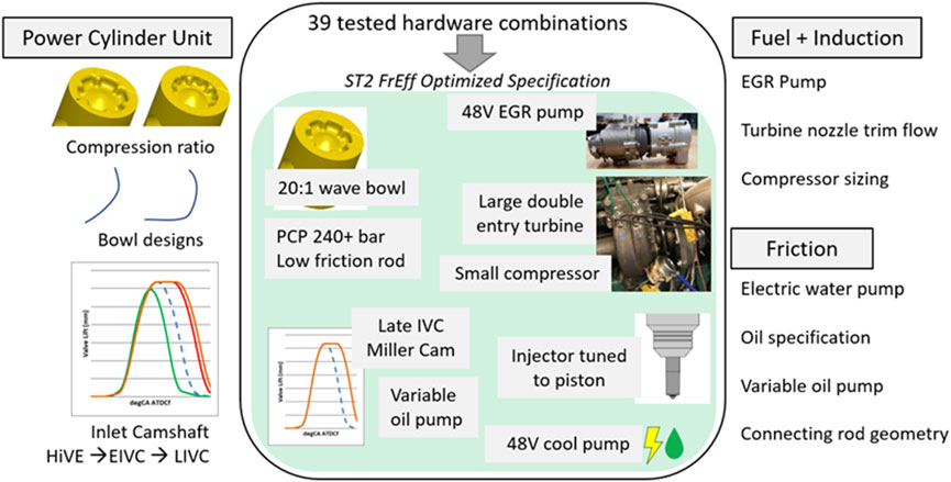
Figure 12. Test items and resultant FE engine specifications from engine development campaigns.
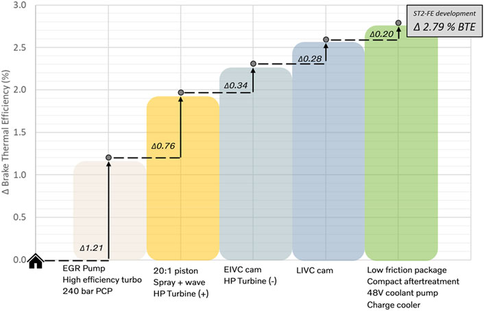
Figure 13. Development path leading to 2.79% BTE increase on 11L ST2-FE engine. Accounting for 48V power consumption adjusts the delta to 2.59% BTE.
The ST2-FE development led to a measured 2.79% BTE improvement at the max efficiency operating point. The ST2-FE engine package then underwent characterization and calibration activities to comply with legislated emissions levels, namely, a limit of 0.20 g/bhph BSNOx on the composite FTP cycle and 1065 RMC cycle, while maximizing in-vehicle fuel efficiency and drivability. The lessons learned from this application of an overexpansion concept would then be applied to the 13L turbocompound ST2-BTE engine with hardware targeting max efficiency for narrowband operation.
Starting with a Volvo 13L turbocompound engine platform, a test campaign was executed to define the ST2-BTE combustion system specifications.
Volvo’s wave piston concept was further developed to maintain good mixing characteristics while being constrained to smaller bowl volume to meet the high compression ratios proposed by 1-D simulation. CFD was used to iterate bowl shapes, and a prototype piston was evaluated on a Volvo single cylinder engine which confirmed heat release characteristics had not been compromised by the small bowl volumes.
Volvo built a 13L turbocompound engine utilizing the latest production intent technology and applied the 48V EGR Pump to begin BTE development testing. Figure 14 shows the installation.
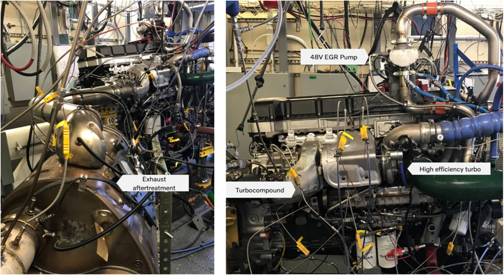
Figure 14. BTE Optimized 13L installation with exhaust aftertreatment at Volvo lab.
Application of the EGR Pump and an elevated cylinder pressure limit produced a ∼0.5% BTE increase. Based on 1-D simulation, several high pressure (HP) and low pressure (LP) nozzles were produced to vary the flow characteristics. Example nozzles are shown in Figure 15. Enabled by the EGR Pump, a LP turbine nozzle with higher flow capacity resulted in a greater expansion ratio across the HP turbine, improving open cycle efficiency and yielding an incremental BTE step of 0.1%.
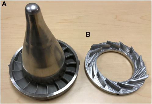
Figure 15. Flow-adjusting nozzles for low pressure turbine (A), high pressure turbine (B).
The 23:1 piston and injector package selected through simulation and single cylinder testing was applied in conjunction with a reciprocating assembly developed to withstand high peak cylinder pressures in exchange for a small FMEP penalty. The prior simulation and testing suggested that the significant increase in geometric compression ratio (more than 4 points) would benefit from Miller cycle volumetric efficiency reduction to moderate peak cylinder pressures and associated friction penalties. An EIVC camshaft was installed with no turbomachinery adjustments, and BTE performance loss of more than 0.5% was observed. As planned during simulation phase, turbine nozzles were trimmed to accommodate the reduced exhaust mass flow, recovering lambda and open-cycle efficiency. However, BTE net improvement of the overexpansion package was only 0.14%. Gross indicated thermal efficiency was lower than anticipated, suggesting that the valve lift profile may be causing an unexpected in-cylinder charge motion change.
The test campaign maintained the overexpansion concept but moved from the EIVC to a LIVC Miller camshaft; an observed restoration of gross indicated thermal efficiency led to a large BTE step of 0.28%, confirming that the tested EIVC profile was not suitable for this concept. A divided inlet manifold was applied, developed to counter the charge reversion through the inlet port caused by IVC during the compression stroke; an improvement in cylinder-to-cylinder IMEP variance was observed in conjunction with an additional ∼0.1% BTE gain.
Reduction of parasitic losses produced a large step of 0.60% BTE by application of a 48V electric coolant pump and adjustments to the oil system. A final series of tests resulted in 0.71% BTE increase through adjustments to fuel rail pressure, injection strategy, improvements to exhaust backpressure and charge cooling. Permitting 290 bar Pcyl,max was useful for extending full load torque, but did not improve max BTE. The hardware selection process is represented in Figure 16. The progress in efficiency culminating in a 2.42% BTE improvement is plotted in Figure 17.
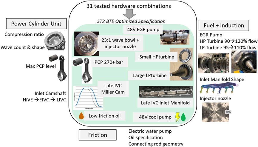
Figure 16. BTE Optimized ST2 engine specification resulting from test campaign.
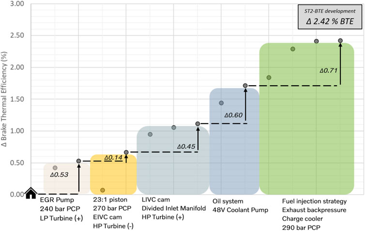
Figure 17. Development path leading to 2.42% BTE increase on 13L turbocompound ST2-BTE engine. Accounting for 48V power consumption adjusts the delta to 2.33% BTE.
The over-expansion concept development was a key factor in the ST2-BTE engine architecture, accounting for nearly half of the thermal efficiency improvements.
This paper describes the research and development process used to pursue a high thermal efficiency heavy-duty engine under Supertruck 2. The team focused on over-expanded engine cycles and advanced piston designs. This paper describes how single-cylinder engine studies using thermal barrier coated pistons, high compression pistons, and over-expanded cycles to inform the development process of a multi-cylinder demonstration engine that achieved 49.9% peak thermal efficiency. The technology suites explored in this work focus substantially on improving the closed cycle efficiency through a combination of Miller cycle and increased compression ratio, which were determined to be complementary, via limiting peak cylinder pressures that would normally accompany increased compression ratio. Improving the open cycle efficiency and reducing parasitic losses via electrification of accessories also contributed to the efficiency gains. The systematic approach pursued in this work shows the benefits of linking exploratory studies (innovation), component studies and integration (development) and numerically driven design development (optimization).
The single-cylinder engine studies showed that thermal barrier coated pistons alone would not provide meaningful efficiency improvements, but paired with over-expansion provide a viable pathway towards increasing efficiency. It was also shown that the benefits of increasing compression ratio could be largely preserved without the associated drawbacks when paired with over-expansion. Greater turbocharger efficiency was shown to be key to achieving the increased efficiency of this combination.
Building on the lessons learned with the single-cylinder studies, the multi-cylinder demonstrator engine showed that combining optimization of fuel rail pressure, fuel injection strategy and valve timing control gave the best outcomes with regard to thermal efficiency. Remarkably, application of the over-expansion cycle accounted for more than half of the thermal efficiency improvement observed.
The datasets presented in this study can be found in online repositories. The names of the repository/repositories and accession number(s) can be found below: University of Michigan Deep Blue, OTIS.
EG: Conceptualization, Data curation, Formal Analysis, Investigation, Methodology, Software, Validation, Writing–original draft, Writing–review and editing. VT: Investigation, Methodology, Validation, Writing–review and editing. JT: Investigation, Methodology, Validation, Writing–review and editing. AB: Conceptualization, Funding acquisition, Project administration, Resources, Supervision, Writing–original draft, Writing–review and editing. MT: Data curation, Methodology, Resources, Supervision, Writing–original draft, Writing–review and editing. JL: Funding acquisition, Methodology, Project administration, Resources, Writing–review and editing.
The author(s) declare that financial support was received for the research, authorship, and/or publication of this article. This work was supported by the Department of Energy, Office of Energy Efficiency and Renewable Energy (EERE), under Award Number DE-EE0007745. The authors also acknowledge co-funding support from the University of Michigan and from Volvo Trucks.
This work was accomplished thanks to the dedication of all the staff at the University of Michigan’s Walter E. Lay Automotive Laboratory. The technical support from Delphi Technologies and Lotus Engineering were also invaluable to the success of these experiments.
Authors MT and JL were employed by Volvo Technology of America, LLC.
The remaining authors declare that the research was conducted in the absence of any commercial or financial relationships that could be construed as a potential conflict of interest.
The author(s) declare that no Generative AI was used in the creation of this manuscript.
All claims expressed in this article are solely those of the authors and do not necessarily represent those of their affiliated organizations, or those of the publisher, the editors and the reviewers. Any product that may be evaluated in this article, or claim that may be made by its manufacturer, is not guaranteed or endorsed by the publisher.
The Supplementary Material for this article can be found online at: https://www.frontiersin.org/articles/10.3389/fther.2024.1517404/full#supplementary-material
Assanis, D., Wiese, K., Schwarz, E., and Bryzik, W. (1991). The effects of ceramic coatings on diesel engine performance and exhaust emissions. SAE Trans. 100, 657–665. doi:10.4271/910460
Benajes, J., Molina, S., Martín, J., and Novella, R. (2009). Effect of advancing the closing angle of the intake valves on diffusion-controlled combustion in a HD diesel engine. Appl. Therm. Eng. 29, 1947–1954. doi:10.1016/j.applthermaleng.2008.09.014
Bryzik, W., and Kamo, R. (1983). TACOM/Cummins adiabatic engine program. SAE Trans. 92, 1063–1087. doi:10.4271/830314
Chen, S. K., and Flynn, P. F. (1965). Development of a single cylinder compression ignition research engine. SAE Tech. Pap. No., 650733. doi:10.4271/650733
Cung, K., Bitsis, D. C., Briggs, T., Miwa, J., Smith, E., Zhang, H., et al. (2022). Demonstration of high compression ratio combustion systems for heavy-duty diesel engine with improved efficiency and lower emissions. SAE Technical Paper No. 2022-01-0427. doi:10.4271/2022-01-0427
De Ojeda, W. (2010). Effect of variable valve timing on Diesel combustion characteristics. SAE Technical Paper No. 2010-01-1124. doi:10.4271/2010-01-1124
Dunbar, W. R., and Lior, N. (1994). Sources of combustion irreversibility. Combust. Sci. Technol. 103, 41–61. doi:10.1080/00102209408907687
Eismark, J., Andersson, M., Christensen, M., Karlsson, A., and Denbratt, I. (2019). Role of piston bowl shape to enhance late-cycle soot oxidation in low-swirl diesel combustion. SAE Int. J. Engines 12, 233–249. doi:10.4271/03-12-03-0017
Eismark, J., and Balthasar, M. (2013). Device for reducing emissions in a vehicle combustion engine. U. S. Pat. Appl. Available at: https://patents.google.com/patent/US8499735B2/en. US Patent# US8499735B2, 2013-08-06
Garcia, E. (2021). Strategies for improving Efficiency and Emissions in heavy-duty diesel engines. Ph.D. Ann Arbor, MI, USA: Department of Mechanical Engineering, University of Michigan.
Garcia, E., Triantopoulos, V., Boehman, A., Taylor, M., and Li, J. (2020) Impact of miller cycle strategies on combustion characteristics, emissions and efficiency in heavy-duty diesel engines. SAE Technical Papers 2020-01-1127.
Garcia, E., Triantopoulos, V., Trzaska, J., Taylor, M., Li, J., and Boehman, A. L. (2023). Extreme Miller cycle with high intake boost for improved efficiency and emissions in heavy-duty diesel engines. Int. J. Engine Res. 24, 552–566. doi:10.1177/14680874211059309
Louis, S. (2014). Expanding combustion knowledge – Lotus AVT system. Lotus Engineering. Available at: https://lotusproactive.wordpress.com/2014/04/09/expanding-combustion-knowledgelotus-avt-system/ (Accessed August 10, 2021).
Mohiuddin, K., Kwon, H., Choi, M., and Park, S. (2021). Effect of engine compression ratio, injection timing, and exhaust gas recirculation on gaseous and particle number emissions in a light-duty diesel engine. Fuel 294, 120547. doi:10.1016/j.fuel.2021.120547
O’Connor, J., Borz, M., Ruth, D., Han, J., Paul, C., Imren, A., et al. (2017). Optimization of an advanced combustion strategy towards 55% BTE for the Volvo SuperTruck program. SAE Int. J. Engines 10, 1217–1227. doi:10.4271/2017-01-0723
Raja, T., Sivanandi, P., Dhandabani, S., and Murugan, V. (2023). Exploratory of novel thermal barrier coating on diesel engine performance. Proc. Institution Mech. Eng. Part E J. Process Mech. Eng. 237, 2083–2092. doi:10.1177/09544089231190541
Somhorst, J., and Oevermann, M. (2024). Effects of thermal barrier coating porosity on combustion and heat losses in a light duty diesel engine. Int. J. Engine Res. 25, 940–958. doi:10.1177/14680874231215526
Somhorst, J., Uczak De Goes, W., Oevermann, M., and Bovo, M. (2019). Experimental evaluation of novel thermal barrier coatings in a single cylinder light duty diesel engine. SAE Technical Paper No. 2019-24-0062. doi:10.4271/2019-24-0062
Stanton, D. W. (2013). Systematic development of highly efficient and clean engines to meet future commercial vehicle greenhouse gas regulations. SAE Int. J. Engines 6, 1395–1480. doi:10.4271/2013-01-2421
United States Department of Energy (2009). “Recovery act-systems level technology development, integration,and demonstration for efficient class 8 trucks (SuperTruck) and advanced technology powertrains for light-duty vehicles (ATP-LD),” in Energy. DE-FOA-0000079 ed.
United States Department of Energy (2016a). Adoption of new fuel efficient technologies from SuperTruck: report to congress.
United States Department of Energy (2016b). Energy department announces $137 million investment in commercial and passenger vehicle efficiency. Available at: https://www.energy.gov/articles/energy-department-announces-137-million-investment-commercial-and-passenger-vehicle.
United States Energy Information Administration (2024). How much carbon dioxide is produced from U.S. gasoline and diesel fuel consumption. Available at: https://www.eia.gov/.
Velusamy, R., Babu, A. S., Swaminathan, M. R., and Hariharan, P. (2024). Evaluation of mechanical, tribological, and thermal characterization of GZ TBCs for heavy duty diesel engine application. J. Mater. Eng. Perform. 33, 2736–2750. doi:10.1007/s11665-023-08164-1
Vos, K. R., Shaver, G. M., Lu, X., Allen, C. M., Mccarthy, J., and Farrell, L. (2019). Improving diesel engine efficiency at high speeds and loads through improved breathing via delayed intake valve closure timing. Int. J. Engine Res. 20, 194–202. doi:10.1177/1468087417743157
Walker, T. K. (2023). Zero emission long-haul heavy-duty trucking. Clean Air Task Force;, 2023. Available at: https://www.catf.us/
Wang, Y., Zeng, S., Huang, J., He, Y., Huang, X., Lin, L., et al. (2005). Experimental investigation of applying Miller cycle to reduce NOx emission from diesel engine. Proc. Institution Mech. Eng. Part A J. Power Energy 219, 631–638. doi:10.1243/095765005x31289
η TC Turbocharger efficiency
λ Air-to-fuel equivalence ratio
°aTDC crank angle degrees after top dead center
BMEP Brake mean effective pressure
BSFC Brake specific fuel consumption
BTE Brake thermal efficiency
CA50 Crank angle at which 50% of total fuel has been burned
CA90 Crank angle at which 90% of total fuel has been burned
CIVC Conventional intake valve closing
CR Compression ratio
EGR Exhaust gas recirculation
EIVC Early intake valve closing
EXMEP Exhaust mean effective pressure
FMEP Friction mean effective pressure
FSN Filter smoke number
gITE Gross indicated thermal efficiency
HTMEP Heat transfer mean effective pressure
IMEP Indicated mean effective pressure
ISFC Indicated specific fuel consumption
ISNO X Indicated specific NOX emissions
IVC Intake valve closing
LIVC Late intake valve closing
MEP Mean effective pressure
nIMEP Net indicated mean effective pressure
PMEP Pumping mean effective pressure
P cyl,max Peak cylinder pressure
SCRE Single cylinder research engine
TBC Thermal barrier coating
Y EGR Exhaust gas recirculation fraction
Keywords: freight efficiency, diesel engine, thermal efficiency, diesel emissions, heavy-duty, Miller cycle, compression ignition, thermal barrier coatings
Citation: Garcia E, Triantopoulos V, Trzaska J, Boehman AL, Taylor M and Li J (2025) Development of a high thermal efficiency heavy-duty engine. Front. Therm. Eng. 4:1517404. doi: 10.3389/fther.2024.1517404
Received: 26 October 2024; Accepted: 20 December 2024;
Published: 10 February 2025.
Edited by:
Pinaki Pal, Argonne National Laboratory (DOE), United StatesReviewed by:
Hailin Li, West Virginia University, United StatesCopyright © 2025 Garcia, Triantopoulos, Trzaska, Boehman, Taylor and Li. This is an open-access article distributed under the terms of the Creative Commons Attribution License (CC BY). The use, distribution or reproduction in other forums is permitted, provided the original author(s) and the copyright owner(s) are credited and that the original publication in this journal is cited, in accordance with accepted academic practice. No use, distribution or reproduction is permitted which does not comply with these terms.
*Correspondence: André L. Boehman, Ym9laG1hbkB1bWljaC5lZHU=
Disclaimer: All claims expressed in this article are solely those of the authors and do not necessarily represent those of their affiliated organizations, or those of the publisher, the editors and the reviewers. Any product that may be evaluated in this article or claim that may be made by its manufacturer is not guaranteed or endorsed by the publisher.
Research integrity at Frontiers
Learn more about the work of our research integrity team to safeguard the quality of each article we publish.