
94% of researchers rate our articles as excellent or good
Learn more about the work of our research integrity team to safeguard the quality of each article we publish.
Find out more
ORIGINAL RESEARCH article
Front. Therm. Eng. , 18 October 2023
Sec. Heat Engines
Volume 3 - 2023 | https://doi.org/10.3389/fther.2023.1265490
This article is part of the Research Topic Current Status, Advances, and Key Future Trends in Heat Engines View all articles
Diesel Particulate Filter (DPF) in the diesel engine exhaust stream needs frequent regeneration (exotherm) to remove captured particulate matter (PM, or soot) without damaging to the porous DPF structure by controlling the peak temperatures and temperature gradients across the DPF. In this study, temperature distribution in a DPF is measured at 42 strategic locations in the test DPF under various regeneration conditions of exhaust flow rates, regeneration temperatures and soot loads. Then a data-based model with feed-forward neural network architecture is designed to model the thermal gradients and temperature dynamics of the DPF during the regeneration process. The neural network feature vector selection, network architecture, hyperparameter calibration process, measured data preprocessing, and experimental data acquisition procedure are evaluated. Over 7,400 experimental data points at various regeneration temperatures, flow rates and soot loads are used in training and validating the neural network model. It is found that the neural network model can accurately predict the 42 DPF bed temperatures simultaneously at different locations, and the time series analysis of both model-predicted and experimentally measured temperatures shows a good correlation. This indicates that the currently developed neural network model can provide spatial distribution of temperature in the DPF, and comprehend the nonlinearity of the temperature dynamics due to DPF soot load at exothermic conditions. These results demonstrate that the data-based model has capability in predicting thermal gradients within a DPF, aiding in determining a safer DPF regeneration strategy, onboard diagnostics and DPF development.
Internal combustion diesel engines have had a considerable impact on the modern world; on the one hand, diesel engines have been the workhorses of the global economies for almost a century and are known for their reliability, efficiency and fuel economy, resulting in their widespread adoption in commercial vehicles, shipping, and energy industries. On the other hand, diesel engine emissions are a significant source of air pollution and global warming, and contributes to various environmental and health problems (Reşitoʇ et al., 2015; Leach et al., 2020; Reitz et al., 2020). The World Health Organization (WHO) has classified diesel engine exhaust as a Group 1 carcinogen, meaning it is a confirmed human carcinogen. Besides the harmful gaseous emissions, the diesel engine has a relatively high particulate emission or trade-off NOx emission compared to gasoline engines (May et al., 2014; Gentner et al., 2017; Das et al., 2020). The diesel particulate matter (PM) emission, also commonly referred to as soot, results from petrochemical combustion and consists of organic and inorganic particles (Xi and Zhong, 2006; Idicheria and Pickett, 2011; Likhanov and Lopatin, 2020). PM has been linked to air quality issues, acid rain, and decreased visibility and can interact with other atmospheric pollutants to form secondary PM resulting in dense smog and a wide range of health problems (Abdel-Rahman, 1998; Walsh, 2001; Khair, 2023). In recent years, governments worldwide have imposed legislative regulations to reduce the emissions from diesel engines and compelled relevant industries to develop new technologies such as diesel particulate filters (DPF) and exhaust gas recirculation (EGR) (Idicheria and Pickett, 2011; Gautam et al., 2016; Winkler et al., 2018; Giechaskiel et al., 2019).
DPF is one of the leading emission control technologies that facilitate the modern diesel engine to meet the mandatory regulatory requirements by regulating the tailpipe out particulate emission (Seo et al., 2012; Kurimoto et al., 2022). DPF is installed in the exhaust stream to trap the particulate emissions and is a critical part of the exhaust after-treatment system, usually located after the diesel oxidation catalyst. DPF consists of a porous ceramic filter (substrate) material, traditionally made of cordierite or silicon carbide, that captures the PM when exhaust gases flow through it (Khair, 2023; Van Setten et al., 2001; Adler, 2005; Fino, 2007). The filtration efficiency of the DPF increases with the trapped PM (soot) but also results in increased pressure drop across the DPF, which has negative consequences on the fuel economy and eventually needs to be regenerated (Legala et al., 2021; Di Sarli and Di Benedetto, 2018). DPF regeneration process removes the soot (PM) trapped by the filter where the PM accumulated is subjected to an oxidation process either passively (no fuel injection) or actively (Konstandopoulos et al., 2000; Di Sarli and Di Benedetto, 2018; Feng et al., 2023). Passive regeneration occurs during regular engine operation, where the soot is removed with the help of NO2 at typical exhaust temperatures between 300°C and 400°C. In contrast, active regeneration is a unique engine operation mode where fuel is dosed into the exhaust stream to create temperatures of more than 550°C to oxidize the soot with the help of O2 in a controlled exothermic process (Boger et al., 2008; Bouchez and Dementhon, 2000). Like any other chemical reaction, reactants (exhaust gas and fuel) composition, flow rates, and temperatures play a critical role in the characteristics of exotherm and thermal gradients during the regeneration process. The primary objective of active DPF regeneration is to quickly oxidize the PM from the filter without damaging it by controlling the exotherms of the regeneration process. However, these exothermic reactions inside the DPF during regeneration create localized thermal stress on the DPF, which leads to a thermal gradient across the DPF and can result in cracking, melting, and other forms of structural damage to the (Merkel et al., 2001; Yang et al., 2016). Excessive exotherm reactions can be caused by improper fuel injection (quantity and timing), insufficient airflow, and overloading of the DPF with soot (Kim and Gauckler, 2012; Haralampous and Koltsakis, 2002; Dabhoiwala et al., 2009; D et al., 2017). The extent of damage will depend on the peak bed temperatures, thermal gradient, geometric dimensions of the filter and the durability of the substrate material (Yang et al., 2016; Kuki et al., 2023). Damaged DPF may not only compromise the filtration efficiency but also create excessive back pressure (where the channels collapse) due to the blockage of exhaust flow resulting in catastrophic failure of diesel engines. Improper regeneration and localized spikes in bed temperatures result in shortening the lifetime of the DPF, requiring costly replacement and a tedious process (yuan Wang et al., 2022; Seiler et al., 2008; Chittipotula, 2021). This problem can be solved by modelling DPF exotherms and understanding the peak bed temperatures, temperature gradients during active regeneration at various regeneration temperatures, soot loads, flow rates, and exhaust fuel injection quantities (Dabhoiwala et al., 2008; Sappok et al., 2017; Chittipotula, 2021). Few of the existing modelling techniques to predict the DPF exotherms and temperature dynamics are discussed as follows:
Bissett (Bissett, 1984) developed a mathematical model for diesel particulate filter thermal regeneration using particle mass balance and energy balance equations where inlet gas temperature, mass velocity, oxygen mass fraction, and soot deposition thickness are considered model inputs to predict wall temperatures and temperature gradients. However, this mathematical model depends on many filter materials, exhaust gas properties and in-situ physical parameter correlation factors. Hoon et al. (Lee and Rutland, 2013) modelled the uncontrolled soot regeneration inside the DPF in the presence of hydrocarbon slip by using a physics-based 0-D modeling technique to predict the transient thermal response, where the temperature, pressure and species concentration of the exhaust across the DPF is considered. In this case, the model assumes that the soot distribution and exhaust species concentration are uniform, which is impractical and relies on the DPF material, geometric parameters and exhaust gas properties. Boopathi (Mahadevan et al., 2015) formulated a multi-zone model for electronic control units to predict substrate temperature by using the lumped model technique based on resistance node methodology; however, this model also assumes the soot distribution and soot inlet rate to be uniform and requires the concentrations and properties of exhaust gas species which is not ideal for the field application. Valeria (Di Sarli and Di Benedetto, 2015) proposed a CFD-based soot regeneration model for catalyzed DPF; here, the model only deals with a single filter channel and is computationally intensive for field application. Aniseh (Abdalla et al., 2017) stimulated the active regeneration process inside the DPF to predict the temperature and differential pressure dynamics with the help of CFD techniques that rely on the filter’s geometrical parameters; however, the system considered only constant exotherm temperature profiles. Zhao (Zhao et al., 2021a) developed a 3-D numerical simulation of soot regeneration on the Fluent platform by considering different regeneration rates, soot loads and oxygen concentrations to predict temperature contours and differential pressure across the DPF. However, this study lacks experimental validation and relies on all the physical properties and chemical reaction kinetics which are difficult to acquire accurately and reliably. Mitesh (Farsodia et al., 2019) successfully demonstrated the application of neural networks to predict the exotherm temperatures during the DPF regeneration and to control the hydrocarbon injection rate during the regeneration, however, there was no emphasis on thermal gradient prediction.
Most existing literature considers the DPF thermal behavior as a complex physics-based time series problem incorporating specific filter material, flow and soot depositions properties, and complex numerical and computational methods to capture the exothermic behavior. To the best of our knowledge, no existing data-based model can accurately track the complete thermal gradient along with the exotherm behavior of DPF during active regeneration. The focus of this study is to tackle the knowledge gap mentioned above in the literature by contributing the following:
1. Development of a comprehensive multi-input multi-output data-based model that can simultaneously predict multiple DPF bed temperatures during active regeneration at various soot loads and exhaust temperatures.
2. Formulation of the DPF thermal behaviour as a regression problem, introducing the engine operating conditions, exhaust stream constituents and DPF spatial temperature data.
3. The proposed model aids in developing a DPF regeneration strategy by accurately predicting the thermal gradient during regeneration across different soot loads, active regeneration temperatures, flow rates and fuel injection.
The objective of the experimental setup was to generate a consistent PM (soot) from a diesel engine and capture the soot with the help of a DPF, followed by an active regeneration process at various conditions. A 15-litre commercially available heavy-duty diesel engine is the platform of choice, which is the most widely used in the transportation industry for class-8 trucks for long-haul heavy-duty cargo logistics. The engine platform is equipped with a high-pressure exhaust gas recirculation (EGR) system and a variable geometry turbocharger (VGT) calibrated to attain a target soot loading rate consistently. The airflow to the engine is measured with the help of a laminar flow element (LFE), fuel flow is measured with a calibrated Bronkhorst flow meter, and the exhaust flow rate (EFR) is calculated by adding the airflow rate and fuel flow rate. The after-treatment system consists of a diesel oxidation catalyst (DOC), DPF and selective catalytic reduction (SCR) catalyst-equipped with a diesel exhaust fluid (DEF) injector, all installed in the original configuration with instrumentation to acquire exhaust temperatures and gas composition data. The DPF is instrumented with multiple thermocouples distributed spatially at critical locations to record bed temperatures. The exhaust gas of the diesel engine is partly then routed through a heat exchanger to further condition the soot to a specific temperature before being captured by the DPF. The soot loading rate (rate of soot captured by DPF) measured in grams per hour is closely controlled by attenuating the exhaust gas temperature, flow rate and oxygen percentage in the exhaust gas with the help of EGR and turbocharger. The following schematic, as shown in Figure 1, illustrates the engine platform and subsequent auxiliary systems in the test cell.
The engine is mainly operated under stock calibration to generate power; however, specific actuators such as the EGR, VGT, and fuel injectors are controlled to reach a particular soot loading rate and regeneration rate. The experimental procedure is as follows: First, the DPF is entirely conditioned by subjecting the DPF to prolonged active regeneration at 625°C to remove any pre-existing soot; this process is referred to as ‘DPF Cleanout’. The DPF is weighed at 200°C to record the initial hot weight, called ‘Clean weight’, and is then loaded with soot (PM) at a predetermined exhaust temperature and O2. In this case, the exhaust temperature is maintained at 250°C with the help of a heat exchanger and O2 concentration in the exhaust is maintained at 9% to ensure that the characteristics of the soot are consistent; this process is called ‘DPF Loading’, and it is ensured that the DPF loading rate is repeatable. DPF is then weighed after the loading procedure to calculate soot weight, which is the net gain in DPF weight. The soot load on the DPF is quantified by grams of soot per litre volume of DPF, and the DPF loading procedure is repeated until it reaches the desired target. Once the DPF is loaded to the desired soot load, the DPF inlet gas is raised to a specific temperature by using the engine post-injection fuel, thereby initiating an active regeneration followed by an immediate engine idling process at various conditions called ‘AR-DTI’. AR-DTI refers to active regeneration (AR) followed by a drop to idle (DTI); the peak DPF inlet temperature before dropping to idle is referred to as AR-DTI temperature and is explicitly illustrated in Figure 2. The DPF spatial thermal gradient data is acquired during the DTI, where peak DPF exothermic reaction occurs due to fuel and oxygen availability during active regeneration and engine idling. The entire experimental procedure is illustrated in Figure 2 as a process flow diagram and with a sample AR-DTI cycle.
Considering the DPF to be cylindrically symmetrical, a quarter of the DPF is instrumented with 47 thermocouples to provide simultaneous spatial bed temperature data at various cross-sections and radial locations; one of the instrumented cross-sections with 19 thermocouples is illustrated in Figure 3.
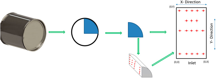
Figure 3. DPF Instrumentation Pattern where the radial direction is represented by X direction, and the dominant axial flow direction by Y direction.
The test matrix for this experiment was developed to cover a broad spectrum of regeneration conditions without damaging the DPF by limiting the DPF bed temperatures to below 900°C during the exotherm. Various DPF soot loads and AR-DTI temperatures (Figure 2) are tabulated in Table 1, summarising the test matrix.
The data acquired during the AR-DTI process is obtained at a 1 Hz sampling rate totaling around 7,400 data points at various exhaust flow rates, temperatures, and pressures. A complete correlation study among the engine operation and exhaust parameters is executed to understand the dominant factors. Data quality is further analyzed to verify the repeatability and parameter trends using pair plots, which allow us to represent both the impact (correlation) and distribution of one variable with other operating variables. Kernel density estimate (KDE) illustrates the diagonal plots data using a continuous probability density curve. The data analytics and parameter correlation results are illustrated graphically using the pair plot shown in Figure 4.
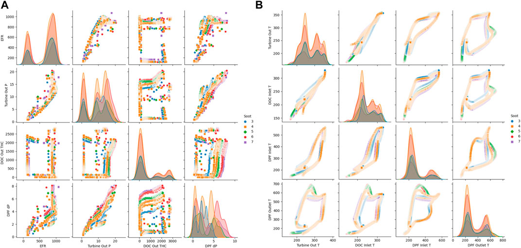
Figure 4. Cross plot for the operating parameters: (A) Exhaust flow parameters, (B) Exhaust temperature parameters.
As shown in Figure 4, the DPF has been subjected to a wide variety of operating conditions, and the data collected during the exothermic active regeneration process shows a good correlation, demonstrating the data quality, i.e., free from measurement noise.
Data-based modeling is a branch of machine learning that involves creating models based on large datasets and has been gaining popularity in thermal engineering for solving complex systems and heat transfer problems (Ban et al., 2022; Erge and van Oort, 2022; Lin et al., 2022; Wang et al., 2022). The goal of data-based modeling is to identify patterns and relationships in the data that can be used to make predictions or gain insights into the underlying processes that generated the data (An et al., 2015; Zhao et al., 2021b; Karniadakis et al., 2021). Data-based modeling in engineering is a powerful tool for analyzing complex nonlinear systems where the established governing principles are too complex to model through equations and material properties. Considering the nonlinearity associated with the DPF exotherm data, a multi-input multi-output regression problem and feed-forward artificial neural network (ANN) architecture is chosen for the prediction of the DPF bed temperatures.
A neural network is a machine-learning algorithm inspired by the human biological brain, which consists of interconnected nodes, or “neurons,” that work together to process and interpret data (Hopfield, 1988; Hammerstrom, 1993; Canziani et al., 2016; Han et al., 2018; Montavon et al., 2018). There are many neural network architectures and the most widely used one for regression problems is the feed-forward ANN architecture consisting of multiple layers: an input layer, some hidden layers, and an output layer. The input layer receives data in numerical values, then processed through the hidden layers, and the output layer produces a final regression result. Each neuron in a neural network is connected to other neurons through a series of weights, determining how strongly the neuron responds to input from other neurons. The training is achieved through a process known as backpropagation, where the network adjusts its weights based on the difference between its predicted output and the actual output (Kim, 1999; Jayalakshmi and Santhakumaran, 2011). By iteratively adjusting its weights in response to feedback, the network can gradually improve its accuracy and better predict future outcomes; these iterations are called ‘epochs’. The critical challenge in designing a feed-forward neural network is determining the optimal architecture for the application, which involves choosing the appropriate number of layers, nodes, and activation functions and tuning the network’s hyperparameters iteratively.
The combination of the activation function in the neuron, the number of hidden layers, and the optimization function are collectively known as hyperparameters, which determine the performance of a neural network. The activation function decides the neuron’s active status based on the input from the previous layer and how it processes the information to the subsequent layers. The most crucial role of activation functions in the hidden layers is introducing nonlinearity to the network; without it, the model cannot mimic complex nonlinear relationships between the input and output. Activation functions also assist in avoiding the problem of vanishing gradients where the gradients become too small during backpropagation, leading to slow or no learning. Increasing the number of hidden layers in a neural network can help the network learn more complex patterns in the data. However, adding too many hidden layers can lead to overfitting, and computational complexity, where the network becomes too complex to process and starts to accommodate the noise in the data. The choice of optimizer can significantly impact the speed at which the neural network converges during training. Optimizers with adaptive learning rates like Adam (Adaptive Moment Estimation) can help avoid local minima problems and feature regularization issues (Saleem et al., 2020).
Data preprocessing is essential to condition the data appropriately, involving filtering, normalization, standardization, feature selection and handling missing values by replacing them with the mean or median of the preceding data. The goal of preprocessing is to prepare the input data to be suitable for the neural network and improve its accuracy without altering the nature or pattern of the data. This study uses the normalization technique to scale the input data to a similar range to normalize parameter sensitivity, help the network converge faster during training, and improve model accuracy (Shen et al., 2021; Sola and Sevilla, 1997). The most common normalization technique is min-max scaling, calculated by subtracting the minimum value from each data point and dividing the result by the total range (the difference between the maximum value and minimum value). The data is not subjected to any further signal filtering (removing outliers) or data augmentation to improve the network robustness to field data.
The input feature vector is a set of input variables used to predict the output variable in a neural network regression problem. It should be chosen based on the domain knowledge of the problem and the data available from either experiments or validated simulations. The prediction attribute is the output variable the neural network tries to predict, also known as the target variable. It is essential to preprocess both the feature vectors and prediction attributes using techniques such as normalization to improve the neural network’s performance after considering the data correlations and governing physics of the internal combustion engine and after-treatment system.
In this case, the temperature generated by exothermic reactions in the DPF is primarily governed by the process of igniting soot in the DPF; therefore, the soot load (amount of soot) present in the DPF directly impacts the temperature. The heat release rate will be governed by the amount (or the concentration) of fuel and oxygen in the exhaust flow that serves as reactants during this exothermic process and must be considered in the modelling. Change in fueling attributes can be incorporated from parameters such as total injected fuel quantity, including main injection and post-injection, the start of fuel injection (timing relative to crank angle), and total unburnt fuel exiting the DOC (raw fuel input to the DPF). During the exothermic process, the initial and subsequent temperatures of the exhaust gas feed in and out of the DPF also play a major role in dictating the heat generation rate and peak temperature inside the DPF. The differential pressure across the DPF and turbine out pressure helps the model to incorporate some resemblance of soot distribution across the DPF because the same soot load can be distributed in various manners (channel plugs, wall deposits), affecting the temperature gradient. The physical attributes such as an instance of regen (time), exhaust flowrate and gas constituents are necessary for the model to incorporate all the changing thermofluid attributes and respective impacts. Considering the above phenomena, a total of 16 feature vectors (inputs) are selected to predict bed temperatures accurately, consisting of engine operation and exhaust flow parameters, as listed in Table 2. It might be mentioned that engine out NOx strongly correlates with the engine out soot, and it might be included as an important feature vector as well. However, NOx emission in diesel engines is normally regulated with EGR based on engine out O2 sensor feedback, as in the present experimental study; so that the impact is accounted for indirectly. As a result, the concentration of NOx is not considered as a part of the feature vector in this study, but instead engine out exhaust O2 concentration is included as one of the feature vectors, as shown in Table 2.
The network’s performance depends on the choice of hyperparameters, fixed design parameters set before training that cannot be learned during training, such as the number of hidden layers, neurons, activation function, learning rate, batch size, dropout probability and optimizers. A standard method for calibrating the hyperparameters is a grid or random search. In grid search, a range of values for each hyperparameter is specified, and the network is trained using all possible combinations of the hyperparameters. In random search, hyperparameters are randomly selected from the specified ranges, and the network is trained using these hyperparameters. The hyperparameters that yield the best performance on the validation set are chosen for the final model. After multiple trials and iterations, a combination of ReLU (Rectified Linear Unit), a non-exponential activation function, and a linear activation function is chosen for DPF thermal modeling. ReLU is mathematically defined as f(x) = max (0, x); The ReLU activation function is computationally efficient, making it a preferred choice for deep neural networks (Apicella et al., 2021; Szandała, 2021). ReLU activation produces sparse representations because it only activates a subset of the neurons in the network, helping to reduce overfitting and to improve generalization. After considering multiple combinations of hyperparameters, the final ANN design attributes are tabulated in Table 3. The final model prediction results are illustrated in Figure 5.
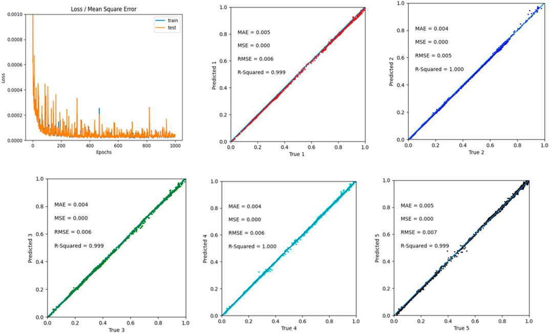
Figure 5. ANN model performance on normalized data after training: Error vs. Epochs and predicted five random temperatures chosen out of 47 presented here (output dataset).
As observed in Figure 5, the trained ANN model accurately predicts the bed temperatures with the hyperparameters given above. Here five-bed temperatures from the set of 47-bed temperatures are selected randomly as a quick method to verify the model’s performance. In the normalized data, the highest temperature is represented as 1, and the lowest is defined as zero. This analysis helps us identify the model performance at extreme (nonlinear) and mid-temperature (relatively linear) sections. If the predicted and experimental values match, all the points plotted will be precisely on the marked trace line; anything below the line is under prediction and above is overprediction by the model, corresponding to an error.
This section evaluates the DTI thermal model performance after training by comparing the model-predicted bed temperatures to their experimental temperatures (true values) during the exothermic reactions. Considering that the representation of all 47 temperatures in graphs is too complicated, a single rectangular cross-section of the quarter DPF with six temperatures at the periphery is used to evaluate the model performance across the various regeneration conditions, as illustrated in Figure 6. The six periphery thermocouples are also designated with alphabets (A-F) for reference in subsequent analysis, as shown in Figure 6. This is because these six temperature values at the periphery of the DPF, including the inlet and exit, centerline and outer cylindrical surface, tend to have the largest errors for the model prediction, arising from the largest impact by the fluid flow, heat transfer with the material properties and pore structures of the DPF, soot distribution, soot oxidation kinetics and heat release rate, and the ambient conditions.
The model performance on the contemporary data (denormalized data) from the periphery thermocouples is illustrated in Figure 7, where the model-predicted bed temperatures are compared to the experimental values at these locations. The periphery location on the DPF exhibits the most significant gradient covering the highest and the lowest bed temperatures during the regeneration process (exothermic reaction). Considering the R2 > 0.999, it can be concluded from Figure 7 that the model prediction across the spectrum is accurate in modeling the thermal gradients.
Figure 8 illustrates the model performance over the time series stitched together by combining various regeneration sequences; here, the model-predicted periphery bed temperatures are plotted against the respective experimental values. Each peak corresponds to an individual regeneration sequence at a specific temperature and soot load. Figure 8 shows bed temperatures at B and F, i.e., the DPF outlet periphery shows the highest exotherms. In contrast, A, C, and D, representing the DPF inlet periphery bed temperatures, show a relatively lower exothermic reaction. As the soot deposition pattern governs the exothermic response, these results agree with the literature, as the soot is predominantly deposited more towards the outlet side of the filter. Figure 8 also illustrates that the model accurately predicts the lower end of the temperature spectrum; however, there is a very slight underprediction at the peak exothermic case, which will contribute to some errors in the DPF thermal gradient calculation.

Figure 8. ANN performance in a time series prediction during multiple regeneration sequences measured vs predicted periphery temperatures at the location of (A) A and B; (B) C and E; (C) D and F.
Plotting all the 18 thermocouple prediction data and comparing them with experimental data using a line plot at various conditions to illustrate model performance is graphically too intensive. This is resolved by creating a contour plot representing the DPF rectangular cross-sectional phase. X represents the radius of the cylindrical DPF, where 0 illustrates the centre of the DPF. Y represents the length of the DPF (from the DPF inlet towards the outlet), and 0 defines the inlet cross section; the contour plot’s thermocouple/bed temperature locations are defined as 2-D cartesian coordinates, as tabulated in Table 4.
The first six (6) DPF regeneration scenarios show the model performance when partial experimental data from these regeneration time series is used to train the model. Scenarios 1 to 6 consist of data used for training and validating where the regeneration conditions vary from light to heavy soot loads (3–7 g/L) at various DPF inlet temperatures (525°C–560°C). 7th scenario can be considered as the model performance on field data where none of the data is ever used for training or validating the model (the neural network model is entirely unexposed to this data). In these scenarios, the DPF is loaded with a predetermined soot level and subjected to an active regeneration process. The DPF inlet exhaust temperature is raised to a specific temperature, referred to as AR-DTI temperature, by injecting fuel into the exhaust stream and immediately dropped to an engine idling condition providing excess oxygen to initiate exothermic soot regeneration. The contour plots presented in Figures 9–14 illustrate a specific instant in the regeneration time series where the peak bed temperatures and maximum thermal gradients occur.
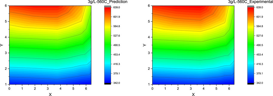
Figure 9. Contour plot for DPF thermal gradient: ANN prediction vs experimental measurement at the soot loading of 3 g/L and the DPF inlet gas temperature of 560°C.
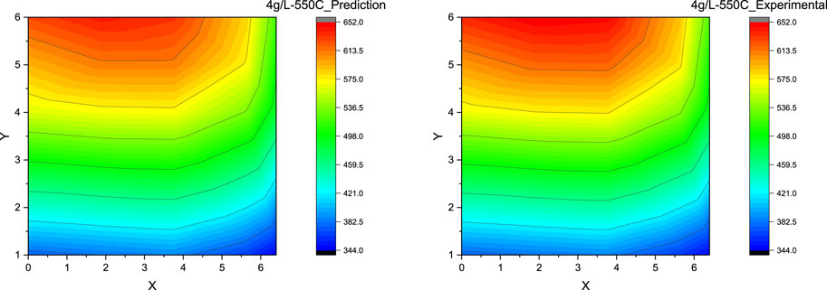
Figure 10. Contour plot for DPF thermal gradient: ANN prediction vs experimental measurement at the soot loading of 4 g/L and the DPF inlet gas temperature of 550°C.
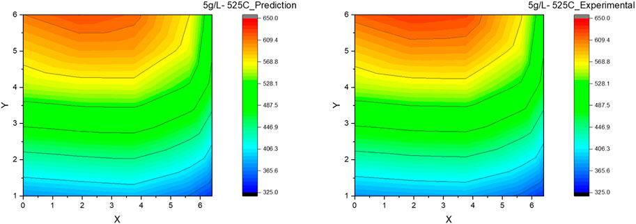
Figure 11. Contour plot for DPF thermal gradient: ANN prediction vs experimental measurement at the soot loading of 4 g/L and the DPF inlet gas temperature of 525°C.
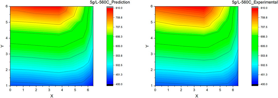
Figure 12. Contour plot for DPF thermal gradient: ANN prediction vs experimental measurement at the soot loading of 5 g/L and the DPF inlet gas temperature of 560°C.
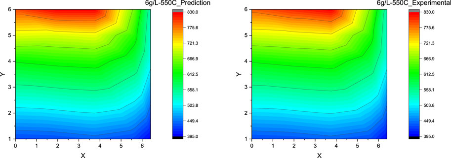
Figure 13. Contour plot for DPF thermal gradient: ANN prediction vs experimental measurement at the soot loading of 6 g/L and the DPF inlet gas temperature of 550°C (Scenario 5).
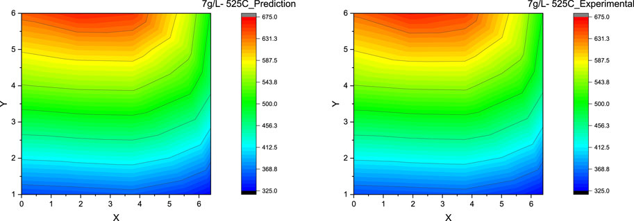
Figure 14. Contour plot for DPF thermal gradient: ANN prediction vs experimental measurement at the soot loading of 7 g/L and the DPF inlet gas temperature of 525°C (Scenario 6).
Scenario 1. Soot Load = 3 g/L, AR-DTI Temperature = 560°C
In scenario 1, a DPF regeneration is considered with a light soot load (3 g/L) and a high DPF inlet gas temperature of 560°C before dropping to idle, as the soot load is relatively low, the thermal gradients are not expected to be high. As observed from Figure 9, the ANN model explicitly predicts the DPF bed temperatures, illustrating an accurate depiction of the DPF thermal gradients at the low soot load of 3 g/L; the maximum error between the predicted and experimental values is around 1%. This evaluation shows that the model can easily predicate the lower end of the thermal gradient spectrum with great accuracy as the relative nonlinearity of the exotherm across the DPF is low.
Scenario 2. Soot Load = 4 g/L, AR-DTI Temperature = 550°C
Scenario 2 illustrates a DPF regeneration with a light to medium soot load (4 g/L) and a high DPF inlet gas temperature of 560°C before dropping to the idle condition; as the soot load is relatively higher, the thermal gradients are also expected to be relatively higher when compared to the previous case, Scenario 1. Figure 10 presents the predicted and experimental DPF thermal gradient during the regeneration process, which is greater than Scenario 1; the model prediction performance in the regions where bed temperatures below 600°C is quite accurate (error <1%), whereas the higher-end temperature prediction error, i.e., >600°C, has increased to around 2% and also shows a slight gradient difference when comparing predicted against experimental thermal gradients closer to the DPF outlet. This difference in prediction and experimental data contours can be primarily attributed to the increased nonlinearity of the exothermic reaction at a higher soot load and higher DPF inlet temperature, for which the model seems not able to capture completely.
Scenario 3. Soot Load = 5 g/L, AR-DTI Temperature = 525°C and Scenario 4: Soot Load = 5 g/L, AR-DTI Temperature = 560°C
Scenario 3 and Scenario 4 are primarily considered to show the impact of DPF inlet temperatures on the thermal gradients during the regeneration. The soot load is kept at a constant 5 g/L (medium soot load) in both scenarios, but the DPF inlet gas temperature in Scenario 3 is maintained lower at 525°C; in contrast, Scenario 4 has its DPF inlet at a higher temperature of 560°C. This change in DPF inlet temperature of 25°C resulted in a peak bed variation of greater than 125°C, demonstrating the nonlinearity in the DPF temperature response to the inlet gas temperature during the exothermic reaction (regeneration). This is understandable since the rate of soot oxidation reaction; hence the heat release rate, is Arrhenius type having strongly nonlinear (exponential) temperature dependence. Similar to Scenario 2, the model prediction at the higher bed temperatures is prone to a minor error in Scenario 3, as observed in the thermal gradient contour plot shown in Figure 11. The maximum error between the prediction and experimental bed temperature values is still around 2%, even at the higher soot loads of 5 g/L, demonstrating excellent model performance at the medium soot loads and lower DPF inlet temperature. Similarly, in Scenario 4, the model prediction error still holds perfect accuracy towards the DPF inlet region (at lower bed temperatures). However, the maximum error at the DPF outlet has increased to around 3% with a relative increase in contour plot distortion when comparing the predicted and experimental values, as shown in Figure 12, which can be again attributed to the model’s limitation in capturing the nonlinearity completely.
Scenario 5. Soot Load = 6 g/L, AR-DTI Temperature = 550°C and Scenario 6: Soot Load = 7 g/L, AR-DTI Temperature = 525°C
Both Scenarios 5 and 6 represent the high soot load conditions (6 g/L and 7 g/L) at both relatively high (550°C) and low (525°C) regeneration temperatures. In both cases, the maximum error between the prediction and experimental value is around 1–2% even when the peak bed temperatures are more than 800°C. It is seen that the ANN model is effectively validated when compared with the experimental results shown, as the model accurately predicts the DPF thermal gradients, as shown in Figure 13 and Figure 14. However, it can be observed that in regeneration conditions at higher DPF inlet temperature (>550°C), the model predictions (contour plots) tend to deviate from the experimental value slightly but still within the acceptable accuracy.
Scenario 7. Soot Load = 4 g/L, AR-DTI Temperature = 560°C (Field Data)
Scenario 7 represents the field data where the model is entirely exposed to new data from the regeneration on the same DPF and engine platform but at a different DPF soot load and active regeneration temperature combination, i.e., 4 g/L and 560°C. It must also be noted that the soot deposition pattern inside the DPF is slightly variable during each regeneration sequence. Figure 15 illustrates the predicted DPF thermal gradient with the experimental values resulting in an error of 8% at the higher temperatures (>600°C) and around 3% at the lower temperatures, even when the model is not trained on any data from this particular case. Considering the exothermic nature of the DPF regeneration, the model accuracy is outstanding on the field data, here the error can be attributed to the model’s limitation in capturing the nonlinearity of the temperature generated due to the exotherm at high DPF inlet temperatures and variability in soot distribution across the DPF.
The percentage error (%) at the various locations and scenarios is tabulated in Table 5, summarizing the DPF thermal ANN model performance as developed. In most cases, the highest error occurs at the peak bed temperature location, i.e., the midpoint of the radius at the outlet side of the DPF. This error is due to the extreme nonlinearity of the exotherm, where the change in bed temperature is quite substantial, even for the slightest change in any input parameter. However, at the lower soot loads and regeneration temperatures, the nonlinearity of the exotherm is lower, resulting in relatively lower peak bed temperatures that the model can more accurately predict. Despite this limitation, an error under 10% is acceptable for non-critical onboard diagnostics or developing DPF regeneration strategies.
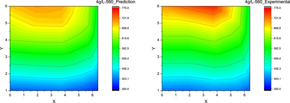
Figure 15. Contour plot for DPF thermal gradient: ANN prediction vs experimental measurement at the soot loading of 4 g/L and the DPF inlet gas temperature of 560°C (Scenario 7 where the experimental data has not been used for the model training and validation, or the so-called unexposed or new data, and the experimental measurement is the field data where the soot distribution may not be as uniform as for the previous scenarios of laboratory tests.).
In this study, a comprehensive data-based diesel particulate filter (DPF) thermal model based on a multi-input multi-output neural network is successfully developed to predict the thermal gradients across the DPF during an active regeneration (exothermic) event. An experimental methodology is formulated to instrument the DPF and generate consistent DPF exotherm temperatures during the active regeneration events. Over 7,400 data points across various exhaust flow rates, regeneration temperatures and soot loads are generated through experimentation and utilized in training, validating and testing the data-based DPF thermal model. The hyperparameters of the neural network model are calibrated to predict the 47 DPF peak bed temperatures simultaneously measured at various spatial locations with an accuracy greater than R2 > 0.999 in most cases. During the neural network performance evaluation, the time series analysis of both model-predicted and experimental bed temperatures shows a good correlation with slight under-prediction at bed temperatures higher than 800°C, which can be attributed to the strong nonlinearity of the exotherm temperature. The thermal contour plots generated by the model-predicted data across the first six scenarios result in an error of <3% when compared with the experimental data, however the contour plot generated by the seventh scenario (field data), the model error rate approaches 10% at DPF outlet locations (bed temperatures >700°C) and 2%–3% at DPF inlet locations (bed temperatures <600°C). These results demonstrate that the data-based model for DPF shows an acceptable level of accuracy in predicting thermal gradients across the spectrum, aiding in determining a safer DPF regeneration strategy, onboard diagnostics and DPF development.
The raw data supporting the conclusion of this article will be made available by the authors, without undue reservation.
AL: Conceptualization, Data curation, Formal Analysis, Methodology, Writing–original draft, Software, Validation, Visualization. VL: Validation, Formal Analysis, Investigation, Writing–review and editing. PW: Funding acquisition, Project administration, Supervision, Writing–review and editing, Resources. XL: Supervision, Writing–review and editing, Funding acquisition, Resources, Validation.
The authors declare that no financial support was received for the research, authorship, and/or publication of this article.
The authors acknowledge Southwest Research Institute (SwRI) and senior management, the Department of Diesel Engines and Emissions R&D, for providing appropriate resources. The authors would also like to acknowledge Michael Chadwell (Program Manager, SwRI), Jacob Rodriguez (Staff Technician, SwRI), Eric Lopez (Technician, SwRI) for their contribution to this program. AL and XL also acknowledge their financial support from the Natural Sciences and Engineering Research Council of Canada (NSERC) via a Discovery Grant.
The author XL declared that they were an editorial board member of Frontiers at the time of submission. This had no impact on the peer review process and the final decision.
The remaining authors declare that the research was conducted in the absence of any commercial or financial relationships that could be construed as a potential conflict of interest.
All claims expressed in this article are solely those of the authors and do not necessarily represent those of their affiliated organizations, or those of the publisher, the editors and the reviewers. Any product that may be evaluated in this article, or claim that may be made by its manufacturer, is not guaranteed or endorsed by the publisher.
Abdalla, A., Wang, G., Zhang, J., and Shuai, S. J. (2017). Simulation of catalyzed diesel particulate filter for active regeneration process using secondary fuel injection Warrendale, Pennsylvania, United States: SAE International. doi:10.4271/2017-01-2287
Abdel-Rahman, A. A. (1998). On the emissions from internal-combustion engines: a review. Int. J. Energy Res. 22 (6), 483–513. doi:10.1002/(sici)1099-114x(199805)22:6<483::aid-er377>3.3.co;2-q
Adler, J. (2005). Ceramic diesel particulate filters. Int. J. Appl. Ceram. Technol. 2 (6), 429–439. doi:10.1111/j.1744-7402.2005.02044.x
An, D., Kim, N. H., and Choi, J. H. (2015). Practical options for selecting data-driven or physics-based prognostics algorithms with reviews. Reliab. Eng. Syst. Saf. 133, 223–236. doi:10.1016/j.ress.2014.09.014
Apicella, A., Donnarumma, F., Isgrò, F., and Prevete, R. (2021). A survey on modern trainable activation functions. Neural Netw. 138, 14–32. doi:10.1016/j.neunet.2021.01.026
Ban, H., Zhang, Y., and Feng, S. (2022). A data-driven approach for real-time prediction of thermal gradient in engineered structures. J. Mech. Sci. Technol. 36 (3), 1243–1249. doi:10.1007/s12206-022-0215-6
Bissett, E. J. (1984). Mathematical model of the thermal regeneration of a wall-flow monolith diesel particulate filter. Chem. Eng. Sci. 39, 1233–1244. doi:10.1016/0009-2509(84)85084-8
Boger, T., Rose, D., Tilgner, I.-C., and Heibel, A. K. (2008). Regeneration strategies for an enhanced thermal management of oxide diesel particulate filters. Warrendale, Pennsylvania, United States: SAE International.
Bouchez, M., and Dementhon, J. B. (2000). Strategies for the control of particulate trap regeneration. Warrendale, Pennsylvania, United States: SAE International.
Canziani, A., Paszke, A., and Culurciello, E. (2016). An analysis of deep neural network models for practical applications. Available: http://arxiv.org/abs/1605.07678.
Chittipotula, T. (2021). Numerical prediction of particulate matter (PM) collection efficiency, loading, and flow characteristics in partially damaged particulate filters with different PM size classes. Emiss. Control Sci. Technol. 7 (4), 302–320. doi:10.1007/s40825-021-00195-1
Deng, Y., Cui, J., E, J., Zhang, B., Zhao, X., Zhang, Z., et al. (2017). Investigations on the temperature distribution of the diesel particulate filter in the thermal regeneration process and its field synergy analysis. Appl. Therm. Eng. 123, 92–102. doi:10.1016/j.applthermaleng.2017.05.072
Dabhoiwala, R. H., Johnson, J. H., Naber, J. D., and Bagley, S. T. (2008). A methodology to estimate the mass of particulate matter retained in a catalyzed particulate filter as applied to active regeneration and on-board diagnostics to detect filter failures. Warrendale, Pennsylvania, United States: SAE International.
Dabhoiwala, R. H., Johnson, J. H., and Naber, J. D. (2009). Experimental study comparing particle size and mass concentration data for a cracked and un-cracked diesel particulate filter. Available: http://www.sae.org.
Das, A., Singh, G., Habib, G., and Kumar, A. (2020). Non-carcinogenic and carcinogenic risk assessment of trace elements of PM2.5 during winter and pre-monsoon seasons in Delhi: a case study. Expo. Health 12 (1), 63–77. doi:10.1007/s12403-018-0285-y
Di Sarli, V., and Di Benedetto, A. (2018). Combined effects of soot load and catalyst activity on the regeneration dynamics of catalytic diesel particulate filters. AIChE J. 64 (5), 1714–1722. doi:10.1002/aic.16047
Di Sarli, V., and Di Benedetto, A. (2015). Modeling and simulation of soot combustion dynamics in a catalytic diesel particulate filter. Chem. Eng. Sci. 137, 69–78. doi:10.1016/j.ces.2015.06.011
Erge, O., and van Oort, E. (2022). Combining physics-based and data-driven modeling in well construction: hybrid fluid dynamics modeling. J. Nat. Gas. Sci. Eng. 97, 104348. doi:10.1016/j.jngse.2021.104348
Farsodia, M., Pandey, S., and Ganguly, G. (2019). Advance data analytics methodologies to solve diesel engine exhaust aftertreatment system challenges Warrendale, Pennsylvania, United States: SAE International. doi:10.4271/2019-01-5035
Feng, R., Hu, X., Li, G., Sun, Z., Ye, M., and Deng, B. (2023). Exploration on the emissions and catalytic reactors interactions of a non-road diesel engine through experiment and system level simulation. Fuel 342, 127746. doi:10.1016/j.fuel.2023.127746
Fino, D. (2007). Diesel emission control: catalytic filters for particulate removal. Sci. Technol. Adv. Mater 8 (1–2), 93–100. doi:10.1016/j.stam.2006.11.012
Gautam, S., Yadav, A., Tsai, C. J., and Kumar, P. (2016). A review on recent progress in observations, sources, classification and regulations of PM2.5 in Asian environments. Environ. Sci. Pollut. Res. 23 (21), 21165–21175. doi:10.1007/s11356-016-7515-2
Gentner, D. R., Jathar, S. H., Gordon, T. D., Bahreini, R., Day, D. A., El Haddad, I., et al. (2017). Review of urban secondary organic aerosol formation from gasoline and diesel motor vehicle emissions. Environ. Sci. Technol. 51 (3), 1074–1093. doi:10.1021/acs.est.6b04509
Giechaskiel, B., Joshi, A., Ntziachristos, L., and Dilara, P. (2019). European regulatory framework and particulate matter emissions of gasoline light-duty vehicles: a review. Catalysts 9 (7), 586. doi:10.3390/catal9070586
Hammerstrom, D. (1993). Working with neural networks. IEEE Spectr. 30 (7), 46–53. doi:10.1109/6.222230
Han, S.-H., Kim, K. W., Kim, S., and Youn, Y. C. (2018). Artificial Neural Network: understanding the basic concepts without mathematics. Dement. Neurocogn Disord. 17 (3), 83. doi:10.12779/dnd.2018.17.3.83
Haralampous, O., and Koltsakis, G. C. (2002). Intra-layer temperature gradients during regeneration of diesel particulate ÿlters. Available: www.elsevier.com/locate/ces.
Hopfield, J. J. (1988). Artificial neural networks. IEEE Circuits Devices Mag. 4 (5), 3–10. doi:10.1109/101.8118
Idicheria, C. A., and Pickett, L. M. (2011). Ignition, soot formation, and end-of-combustion transients in diesel combustion under high-EGR conditions. Int. J. Engine Res. 12 (4), 376–392. doi:10.1177/1468087411399505
Jayalakshmi, T., and Santhakumaran, A. (2011). Statistical normalization and back propagationfor classification. Int. J. Comput. Theory Eng., 89–93. doi:10.7763/ijcte.2011.v3.288
Karniadakis, G. E., Kevrekidis, I. G., Lu, L., Perdikaris, P., Wang, S., and Yang, L. (2021). Physics-informed machine learning. Nat. Rev. Phys. 3 (6), 422–440. doi:10.1038/s42254-021-00314-5
Khair, M. K. (2023). A review of diesel particulate filter technologies. Warrendale, Pennsylvania, United States: SAE.
Kim, D. (1999). Normalization methods for input and output vectors in Backpropagation neural networks. Int. J. Comput. Math. 71 (1–2), 161–171. doi:10.1080/00207169908804800
Kim, I. J., and Gauckler, L. G. (2012). Formation, decomposition and thermal stability of Al2TiO 5 ceramics. J. Ceram. Sci. Technol. 3 (2), 49–60. doi:10.4416/JCST2011-00049
Konstandopoulos, A. G., Kostoglou, M., Skaperdas, E., Papaioannou, E., Zarvalis, D., and Kladopoulou, E. (2000). Fundamental studies of diesel particulate filters: transient loading, regeneration and aging. SAE Technical Paper 2000-01-1016. doi:10.4271/2000-01-1016
Kuki, T., Miyairi, Y., Kasai, Y., Miyazaki, M., and Miwa, S. (2023). Study on reliability of wall-flow type diesel particulate filter. Warrendale, Pennsylvania, United States: SAE International.
Kurimoto, Y., et al. (2022). Next generation diesel particulate filter for future tighter HDV/NRMM emission regulations Warrendale, Pennsylvania, United States: SAE International. doi:10.4271/2022-01-0545
Leach, F., Kalghatgi, G., Stone, R., and Miles, P. (2020). The scope for improving the efficiency and environmental impact of internal combustion engines. Transp. Eng. 1, 100005. doi:10.1016/j.treng.2020.100005
Lee, H., and Rutland, C. J. (2013). Modeling uncontrolled regeneration of diesel particulate filters, taking into account hydrocarbon slip. Proc. Institution Mech. Eng. Part D J. Automob. Eng. 227 (2), 281–296. doi:10.1177/0954407012450837
Legala, A., Premnath, V., Chadwell, M., Weber, P., and Khalek, I. (2021). Impact of selective catalytic reduction process on nonvolatile particle emissions Warrendale, Pennsylvania, United States: SAE International. doi:10.4271/2021-01-0624
Likhanov, V. A., and Lopatin, O. P. (2020). “Dynamics of soot formation and burnout in a gas diesel cylinder,” in IOP conference series: materials science and engineering (Bristol, United Kingdom: Institute of Physics Publishing). doi:10.1088/1757-899X/862/6/062033
Lin, J., Lin, W., Lin, W., Wang, J., and Jiang, H. (2022). Thermal prediction for Air-cooled data center using data Driven-based model. Appl. Therm. Eng. 217, 119207. doi:10.1016/j.applthermaleng.2022.119207
Mahadevan, B. S., Johnson, J. H., and Shahbakhti, M. (2015). Development of a catalyzed diesel particulate filter multi-zone model for simulation of axial and radial substrate temperature and particulate matter distribution. Emiss. Control Sci. Technol. 1 (2), 183–202. doi:10.1007/s40825-015-0015-x
May, A. A., Nguyen, N. T., Presto, A. A., Gordon, T. D., Lipsky, E. M., Karve, M., et al. (2014). Gas- and particle-phase primary emissions from in-use, on-road gasoline and diesel vehicles. Atmos. Environ. 88, 247–260. doi:10.1016/j.atmosenv.2014.01.046
Merkel, G. A., Cutler, W. A., and Warren, C. J. (2001). Thermal durability of wall-flow ceramic diesel particulate filters. Warrendale, Pennsylvania, United States: SAE International.
Montavon, G., Samek, W., and Müller, K. R. (2018). Methods for interpreting and understanding deep neural networks. Digital Signal Process. A Rev. J. 73, 1–15. doi:10.1016/j.dsp.2017.10.011
Reitz, R. D., Ogawa, H., Payri, R., Fansler, T., Kokjohn, S., Moriyoshi, Y., et al. (2020). IJER editorial: the future of the internal combustion engine. Int. J. Engine Res. 21 (1), 3–10. doi:10.1177/1468087419877990
Reşitoʇlu, I. A., Altinişik, K., and Keskin, A. (2015). The pollutant emissions from diesel-engine vehicles and exhaust aftertreatment systems. Clean Technol. Environ. Policy 17 (1), 15–27. doi:10.1007/s10098-014-0793-9
Saleem, M. H., Potgieter, J., and Arif, K. M. (2020). Plant disease classification: a comparative evaluation of convolutional neural networks and deep learning optimizers. Plants 9 (10), 1319–1417. doi:10.3390/plants9101319
Sappok, A., Ragaller, P., Herman, A., Bromberg, L., Prikhodko, V., Parks, J., et al. (2017). On-board particulate filter failure prevention and failure diagnostics using radio frequency sensing. SAE Int. J. Engines 10 (4), 1667–1682. doi:10.4271/2017-01-0950
Seiler, V., Boeckmann, E., and Eilts, P. (2008). Performance of undamaged and damaged diesel particulate filters. Warrendale, Pennsylvania, United States: SAE International.
Seo, J. M., Park, W. S., and Lee, M. J. (2012). The best choice of gasoline/diesel particulate filter to meet future particulate matter regulation Warrendale, Pennsylvania, United States: SAE International. doi:10.4271/2012-01-1255
Shen, Y., Wang, J., and Navlakha, S. (2021). A correspondence between normalization strategies in artificial and biological neural networks. Neural comput., 33 (12), 3179–3203. doi:10.1162/neco_a_01439
Sola, J., and Sevilla, J. (1997). Importance of input data normalization for the application of neural networks to complex industrial problems. IEEE Trans. Nucl. Sci. 44, 1464–1468. doi:10.1109/23.589532
Szandała, T. (2021). “Review and comparison of commonly used activation functions for deep neural networks,” in Studies in computational intelligence (Berlin, Germany: Springer), 203–224. doi:10.1007/978-981-15-5495-7_11
Van Setten, B. A. A. L., Makkee, M., and Moulijn, J. A. (2001). Science and technology of catalytic diesel particulate filters. Catal. Rev. - Sci. Eng. 43 (4), 489–564. doi:10.1081/CR-120001810
Walsh, M. P. (2001). Global trends in diesel emissions regulation-A 2001 update. SAE Technical Paper 2001-01-0183. doi:10.4271/2001-01-0183
Wang, J., Li, Y., Gao, R. X., and Zhang, F. (2022). Hybrid physics-based and data-driven models for smart manufacturing: modelling, simulation, and explainability. J. Manuf. Syst. 63, 381–391. doi:10.1016/j.jmsy.2022.04.004
Winkler, S. L., Anderson, J. E., Garza, L., Ruona, W. C., Vogt, R., and Wallington, T. J. (2018). Vehicle criteria pollutant (PM, NOx, CO, HCs) emissions: how low should we go? NPJ Clim. Atmos. Sci. 1 (1), 26. doi:10.1038/s41612-018-0037-5
Xi, J., and Zhong, B. J. (2006). Soot in diesel combustion systems. Chem. Eng. Technol. 29 (6), 665–673. doi:10.1002/ceat.200600016
Yang, K., Fox, J. T., and Hunsicker, R. (2016). Characterizing diesel particulate filter failure during commercial fleet use due to pinholes, melting, cracking, and fouling. Emiss. Control Sci. Technol. 2 (3), 145–155. doi:10.1007/s40825-016-0036-0
yuan Wang, D., Cao, J. h., Tan, P. q., Wang, Z. x., Li, W. l., Liu, Z. w., et al. (2022). Full course evolution characteristics of DPF active regeneration under different inlet HC concentrations. Fuel 310, 122452. doi:10.1016/j.fuel.2021.122452
Zhao, J., Li, X., Shum, C., and McPhee, J. (2021b). A Review of physics-based and data-driven models for real-time control of polymer electrolyte membrane fuel cells. Energy AI 6, 100114. doi:10.1016/j.egyai.2021.100114
Keywords: artificial neural network (ANN), diesel particulate filter (DPF), particulate matter (PM), active regeneration, exotherm reaction, temperature gradient modeling
Citation: Legala A, LakkiReddy V, Weber P and Li X (2023) Modeling of diesel particulate filter temperature dynamics during exotherm using neural networks. Front. Therm. Eng. 3:1265490. doi: 10.3389/fther.2023.1265490
Received: 23 July 2023; Accepted: 05 October 2023;
Published: 18 October 2023.
Edited by:
Haifeng Liu, Tianjin University, ChinaReviewed by:
Jianbing Gao, Beijing Institute of Technology, ChinaCopyright © 2023 Legala, LakkiReddy, Weber and Li. This is an open-access article distributed under the terms of the Creative Commons Attribution License (CC BY). The use, distribution or reproduction in other forums is permitted, provided the original author(s) and the copyright owner(s) are credited and that the original publication in this journal is cited, in accordance with accepted academic practice. No use, distribution or reproduction is permitted which does not comply with these terms.
*Correspondence: Phillip Weber, cHdlYmVyQHN3cmkub3Jn; Xianguo Li, eGlhbmd1by5saUB1d2F0ZXJsb28uY2E=
Disclaimer: All claims expressed in this article are solely those of the authors and do not necessarily represent those of their affiliated organizations, or those of the publisher, the editors and the reviewers. Any product that may be evaluated in this article or claim that may be made by its manufacturer is not guaranteed or endorsed by the publisher.
Research integrity at Frontiers

Learn more about the work of our research integrity team to safeguard the quality of each article we publish.