- 1William B. Hanson Center for Space Sciences, University of Texas at Dallas, Richardson, TX, United States
- 2Department of Physics, Auburn University, Auburn, AL, United States
Both proton ring and shell distributions, providing a positive gradient along the perpendicular direction, can trigger ion Bernstein instabilities and excite magnetosonic (MS) waves in the Earth’s inner magnetosphere. A thorough comparison of the ion Bernstein instability due to the proton ring and shell distributions has not been performed. In this study, we perform and compare the MS wave instabilities under different wave normal angles and parameters of ring and shell distributions. We find that (1) compared to shell-driven MS waves, ring-driven MS waves have narrower frequency and wavenumber ranges. (2) The peak growth rates of shell-driven MS waves are always near the first peaks of the square of first-kind Bessel function
Highlights
• Compared to shell-driven MS waves, ring-driven MS waves have narrower frequency and wavenumber ranges.
• The peak growth rates of shell-driven MS waves are always near the first peaks of the square of the Bessel function
• The peak growth rates of ring-driven MS waves are near the first peak of
1 Introduction
Magnetosonic (MS) waves, also known as the ion Bernstein mode (IBM) or equatorial noise, are electromagnetic emissions with frequencies between the proton gyrofrequency and the lower hybrid resonant frequency (Laakso et al., 1990; Perraut et al., 1982; Santolík et al., 2004; Liu et al., 2018). The wave magnetic field is nearly linearly polarized, while the wave electric field is nearly circularly polarized. MS waves propagate quasi-perpendicularly to the ambient magnetic field and are thus confined near the geomagnetic equator (Russell et al., 1970; Santolík et al., 2002; Němec et al., 2005; Min et al., 2020). They occur both inside and outside the plasmasphere (Chen and Thorne, 2012; Xiao et al., 2012; Hrbáčková et al., 2015) with typical statistical amplitudes of
MS waves have been investigated more in recent years due to their potential roles in accelerating and scattering energetic and relativistic electrons in the magnetosphere. Using quasi-linear theory and test particle simulations, it has been demonstrated that MS waves can scatter radiation belt MeV electrons through Landau resonance (Horne et al., 2007; Li et al., 2014), kick equatorially mirroring electrons out of the equatorial plane through bounce resonance (Chen, 2015; Li et al., 2015), and scatter electrons over the finite latitudinal extend near the magnetic equator through transit time scattering (Bortnik and Thorne, 2010).
MS waves can be excited near the perpendicular direction by the ion Bernstein instability, which is associated with a proton ring (Boardsen et al., 1992; Balikhin et al., 2015; Chen et al., 2010a; Gary et al., 2010) or shell distribution (Ashour-Abdalla et al., 2006; Liu et al., 2011; Min and Liu, 2015; Gao et al., 2017), providing a positive gradient in the proton velocity space distribution function (Chen et al., 2010a; Curtis and Wu, 1979; Gary et al., 2010; Liu et al., 2011). This physical mechanism has been confirmed by the consistent results of observations (e.g., Boardsen et al., 1992; Ashour-Abdalla et al., 2006; Balikhin et al., 2015), kinetic linear dispersion theory (Ashour-Abdalla et al., 2006; Gary et al., 2010; Min and Liu, 2015; Min and Liu, 2016a; Min et al., 2018), and numerical simulations (e.g., Chen, et al., 2010b; Liu et al., 2011; Chen et al., 2018; Min et al., 2020). Min and Liu (2016b) addressed differences of the MS wave linear growth rate patterns driven by the ring and shell velocity distributions. They used the cold plasma dispersion relation to approximate the MS wave frequencies and wavenumbers, and linear growth rates were determined only by the ring (shell) populations. They find that the growth rates of the ring-driven MS waves peak at the discrete harmonics of the proton gyrofrequency in quasi-perpendicular direction. Once wave normal angle decreases, those unstable modes broaden in frequency and eventually evolve to a continuum in the wave spectrum. Conversely, unstable modes driven by the proton shell are confined to a relatively small parallel wavenumber
Thus, in this study, we will perform a parametric comparison study of MS wave instability by proton ring and shell distributions by using a full wave dispersion relation solver. In Section 2, methodologies for instability analysis and shell distribution configuration are introduced. We provide a comparison of ring-driven and shell-driven MS waves in Section 3 and then present parametric dependences of ring/shell velocity, temperature and wave normal angles on the MS wave instability in Section 4, followed by the conclusion and discussion in Section 5.
2 Methodology
To perform instability analyses, we use a numerical electromagnetic linear wave dispersion relation and instability solver for Maxwellian ring-beam distributions (Umeda et al., 2012). The Maxwellian ring-beam distribution
where
The isotropic shell distribution can be written as (Min and Liu, 2015):
where
Figures 1A, C show examples of isotropic ring and configured isotropic shell distributions with same density and temperature, respectively. The shell distribution is configured by 28 ring-beam distributions. According to Chen (2015), MS wave instability is dominated by resonant instability caused by the resonant protons near the
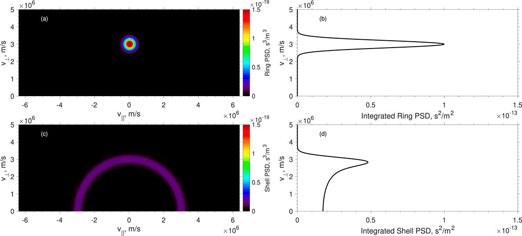
Figure 1. An example of proton ring and shell distributions. (A) Ring distribution (
3 MS waves excited by ring and shell distributions
To investigate MS wave instability dependence, we use the numerical electromagnetic linear wave dispersion relation and instability solver. Such solver is extended to Maxwellian ring-beam distributions and tested by the particle-in-cell (PIC) simulation (Liu et al., 2022). Figure 2 shows a comparison of dispersion relations and growth rates of the ring-driven (left column) and shell-driven (right column) MS waves. Two black lines denote the cold dispersion relations. The large solid circles denote the growing modes, and the color denotes the growth rate values. The black squares denotes the first peaks of
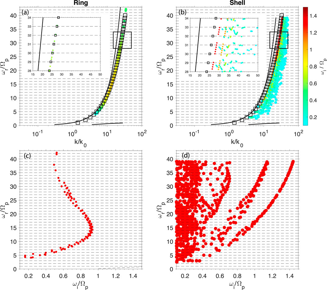
Figure 2. Comparison of the (A, C) ring-driven and (B, D) shell-driven MS waves using the full wave dispersion relation solver. (A, B) Full wave dispersion relations of ring-driven and shell-driven MS waves, respectively. Two black curves denote the cold plasma dispersion relations. The colored solid circles denote the growing modes. The black squares denote the first peak of the square of the Bessel function
Both ring and shell distributions can excite MS waves near the wavenumber corresponding to the first peak of
To achieve a large growth rate,
4 MS wave dependences on proton ring and shell distributions
In this section, we investigate the dependencies of MS wave instability on the velocity and temperature of proton ring and shell distributions and wave normal angles. We vary one of the three parameters and fix the other two at a time. The typical plasma parameters are shown in Section 2. To maintain the shell distribution, we change the numbers of ring-beam distributions used for the shell distribution configuration when the shell velocity or thermal velocity changes. For the sake of visualization, we only show the wave frequencies and growth rates for the peak growth rate in each harmonic band instead of showing all growing and damped modes.
4.1 Ring and shell velocity
Figure 3 shows the MS wave frequency and growth rate dependences on the velocity of proton ring (Figures 3A–H) and shell (Figures 3I–P) distributions for
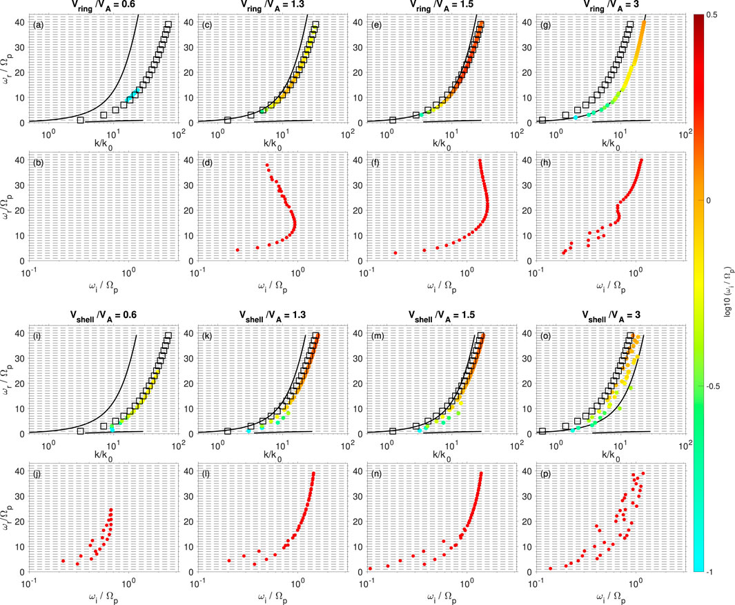
Figure 3. MS wave dependence on the velocity of the (A–H) ring and (I–P) shell distributions.
Once
4.2 Ring and shell temperature
Figure 4 shows the MS wave frequency and growth rate dependences on the thermal velocity (temperature) of the proton ring (Figures 4A–F) and shell (Figures 4G–L) distributions for
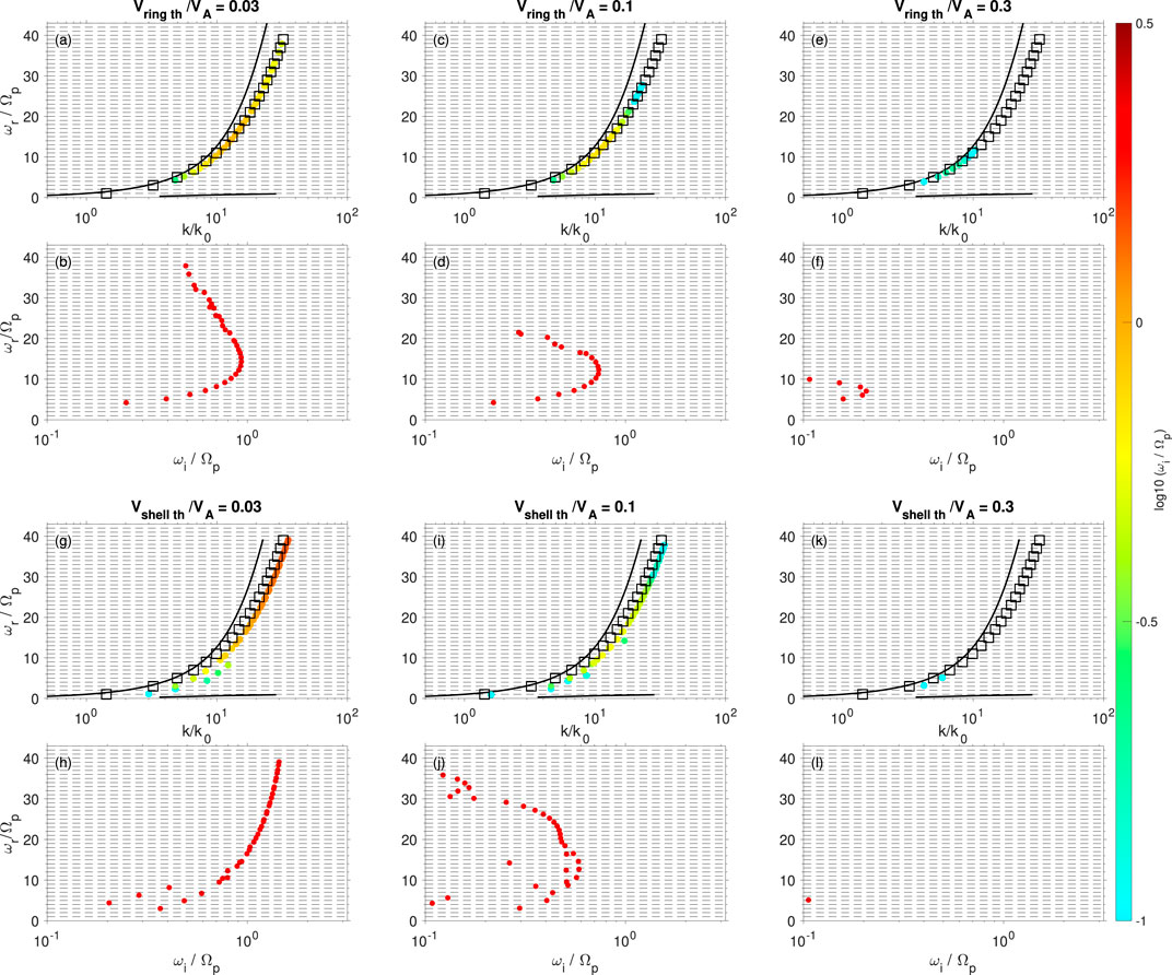
Figure 4. MS wave dependence on the thermal velocity (temperature) of the (A–F) ring and (G–L) shell distributions.
4.3 Wave normal angle
Figure 5 shows the wave frequency and growth rate dependences on the wave normal angle for ring-driven (Figures 5A–F) and shell-driven (Figures 5G–L) MS waves with
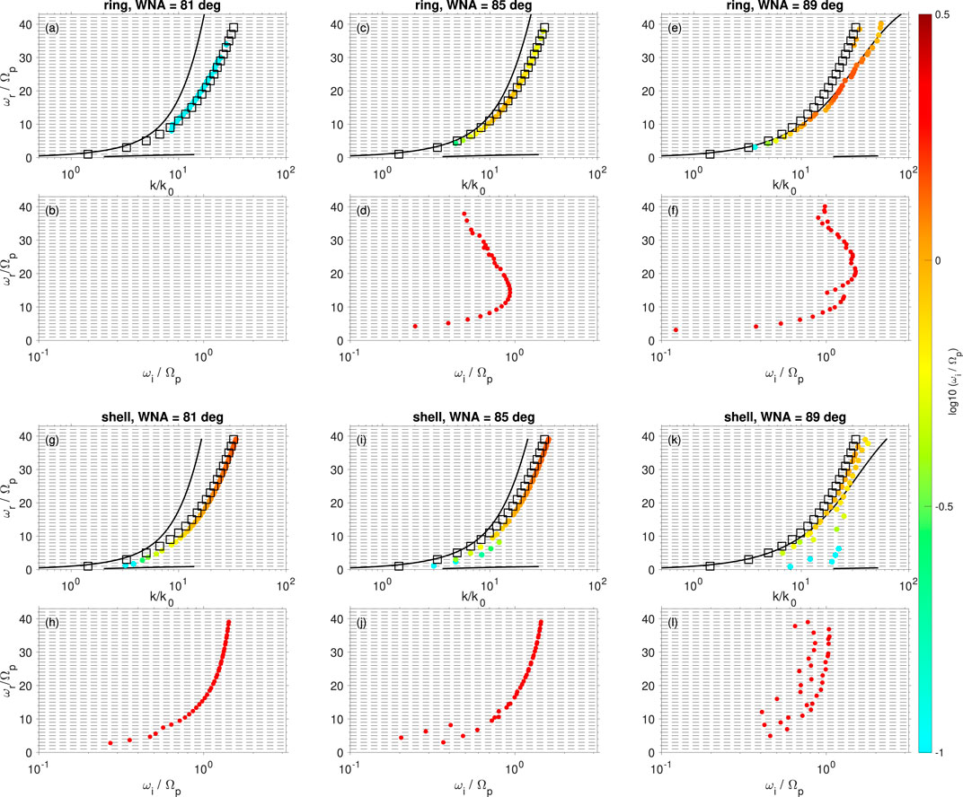
Figure 5. MS wave dependence on wave normal angles (WNAs) for (A–F) ring-driven and (G–L) shell-driven MS waves.
The ring (shell) velocity and WNA dependences can be summarized by the relations between
5 Conclusion and discussion
In this study, we perform a parametric analysis of ring-driven and shell-driven MS waves by investigating their dependencies on the velocities and temperatures of the proton ring and shell distributions and wave normal angles using a full wave dispersion relation solver. The principal conclusions of this study are as follows.
1. Compared to shell-driven MS waves, ring-driven MS waves have narrower wavenumber ranges and narrower frequency ranges. This result occurs primarily because the ring distribution can provide a positive phase space density gradient along
2. The MS wave growth rates increase as the ratio of
3. The MS wave growth rates and frequency range decrease with increasing temperature of the ring (shell) distribution due to the smoothed phase space density by increasing the temperature.
In Figure 3, the MS wave frequency always extends from the low harmonic bands to high harmonic bands as the ring (shell) velocity increases. This phenomenon is different from a previous study, in which a proton ring with a small velocity excites high harmonic bands and a proton ring with a large velocity excites low harmonic bands (Chen et al., 2010b). This discrepancy is caused by the fact that the MS waves were studied under cold plasma conditions in Chen et al., 2010a, and the wave normal angle was quite large
The ring (shell)-driven MS waves (Figures 2A,B) show continuous growth rates across the proton harmonics. They correspond to continuous frequency spectra of MS waves (Gurnett, 1976; Tsurutani et al., 2014). The typical discrete MS waves can transit to continuous spectra once the growth rate satisfies
Recently, a partial shell distribution was found in observations (Boardsen et al., 2018; Min et al., 2018; Ouyang et al., 2020) and simulations (Chen, Thorne, Jordanova, Wang, et al., 2010). This distribution acts as a shell distribution but is limited in a finite pitch angle range centered along the perpendicular direction so that it can be treated as a transition distribution between the two extreme cases, ring and shell distributions. Thus, the properties of the partial shell-driven MS waves should be in between the properties of the ring-driven and shell-driven MS waves and thus follow similar parametric dependences. Investigating this topic will be left for future research.
In this work, we use typical background parameters in the inner magnetosphere (such as background magnetic field and cold plasma density and temperature) and a realistic proton-electron-mass ratio. The dispersion relation and peak growth rates are highly dependent on the relation between the cold plasma wave mode and the first peak of
In the Earth’s inner magnetosphere, ring and shell distributions can be formed at the dayside due to the energy-dependent proton drift paths. These ring or shell distributions will drive MS waves, and then, be relaxed after the wave excitation. Thus, how these distribution relaxations influence the proton drift and distribution is a significant topic in the wave-particle interaction, which we will address in the future.
Data availability statement
The datasets presented in this study can be found in online repositories. The names of the repository/repositories and accession number(s) can be found below: https://doi.org/10.5281/zenodo.11521879.
Author contributions
XL: Data curation, Formal Analysis, Investigation, Methodology, Software, Writing–original draft, Writing–review and editing. LC: Conceptualization, Funding acquisition, Supervision, Writing–review and editing. XW: Resources, Validation, Writing–review and editing.
Funding
The author(s) declare that financial support was received for the research, authorship, and/or publication of this article. The authors acknowledge NASA fundings NNX17AI52G, 80NSSC19K0283, 80NSSC20K0689, 80NSSC21K1679, and 80NSSC22K1637.
Conflict of interest
The authors declare that the research was conducted in the absence of any commercial or financial relationships that could be construed as a potential conflict of interest.
The reviewer IS declared a past co-authorship with the author LC to the handling editor.
Publisher’s note
All claims expressed in this article are solely those of the authors and do not necessarily represent those of their affiliated organizations, or those of the publisher, the editors and the reviewers. Any product that may be evaluated in this article, or claim that may be made by its manufacturer, is not guaranteed or endorsed by the publisher.
References
Ashour-Abdalla, M., Leboeuf, J. N., Schriver, D., Bosqued, J.-M., Cornilleau-Wehrlin, N., Sotnikov, V., et al. (2006). Instabilities driven by ion shell distributions observed by cluster in the midaltitude plasma sheet boundary layer. J. Geophys. Res. Space Phys. 111 (A10). doi:10.1029/2005JA011490
Balikhin, M. A., Shprits, Y. Y., Walker, S. N., Chen, L., Cornilleau-Wehrlin, N., Dandouras, I., et al. (2015). Observations of discrete harmonics emerging from equatorial noise. Nat. Commun. 6 (1), 7703. doi:10.1038/ncomms8703
Boardsen, S. A., Gallagher, D. L., Gurnett, D. A., Peterson, W. K., and Green, J. L. (1992). Funnel-shaped, low-frequency equatorial waves. J. Geophys. Res. Space Phys. 97 (A10), 14967–14976. doi:10.1029/92JA00827
Boardsen, S. A., Hospodarsky, G. B., Min, K., Averkamp, T. F., Bounds, S. R., Kletzing, C. A., et al. (2018). Determining the wave vector direction of equatorial fast magnetosonic waves. Geophys. Res. Lett. 45 (16), 7951–7959. doi:10.1029/2018GL078695
Bortnik, J., and Thorne, R. M. (2010). Transit time scattering of energetic electrons due to equatorially confined magnetosonic waves. J. Geophys. Res. 115, 7213. doi:10.1029/2010JA015283
Chen, L. (2015). Wave normal angle and frequency characteristics of magnetosonic wave linear instability. Geophys. Res. Lett. 42 (12), 4709–4715. doi:10.1002/2015GL064237
Chen, L., Sun, J., Lu, Q., Gao, X., Xia, Z., and Zhima, Z. (2016). Generation of magnetosonic waves over a continuous spectrum. J. Geophys. Res. Space Phys. 121 (2), 1137–1147. doi:10.1002/2015JA022089
Chen, L., Sun, J., Lu, Q., Wang, X., Gao, X., Wang, D., et al. (2018). Two-dimensional particle-in-cell simulation of magnetosonic wave excitation in a dipole magnetic field. Geophys. Res. Lett. 45 (17), 8712–8720. doi:10.1029/2018GL079067
Chen, L., and Thorne, R. M. (2012). Perpendicular propagation of magnetosonic waves. Geophys. Res. Lett. 39 (14). doi:10.1029/2012GL052485
Chen, L., Thorne, R. M., Jordanova, V. K., and Horne, R. B. (2010a). Global simulation of magnetosonic wave instability in the storm time magnetosphere. J. Geophys. Res. 115. doi:10.1029/2010JA015707
Chen, L., Thorne, R. M., Jordanova, V. K., Wang, C., Gkioulidou, M., Lyons, L., et al. (2010b). Global simulation of EMIC wave excitation during the 21 April 2001 storm from coupled RCM-RAM-HOTRAY modeling. J. Geophys. Res. 115, 7209. doi:10.1029/2009JA015075
Curtis, S. A., and Wu, C. S. (1979). Gyroharmonic emissions induced by energetic ions in the equatorial plasmasphere. J. Geophys. Res. 84, 2597–2607. doi:10.1029/JA084iA06p02597
Gao, X., Liu, K., Wang, X., Min, K., Lin, Y., and Wang, X. (2017). Gyrokinetic electron and fully kinetic ion simulations of fast magnetosonic waves in the magnetosphere. Phys. Plasmas 24 (6), 062901. doi:10.1063/1.4985303
Gary, S. P., Liu, K., Winske, D., and Denton, R. E. (2010). Ion Bernstein instability in the terrestrial magnetosphere: linear dispersion theory. J. Geophys. Res. Space Phys. 115, A12209. doi:10.1029/2010JA015965
Gurnett, D. A. (1976). Plasma wave interactions with energetic ions near the magnetic equator. J. Geophys. Res. 81, 2765–2770. doi:10.1029/JA081i016p02765
Horne, R. B., Thorne, R. M., Glauert, S. A., Meredith, N. P., Pokhotelov, D., and Santolík, O. (2007). Electron acceleration in the Van Allen radiation belts by fast magnetosonic waves. Geophys. Res. Lett. 34, L17107. doi:10.1029/2007GL030267
Hrbáčková, Z., Santolík, O., Němec, F., Macúšová, E., and Cornilleau-Wehrlin, N. (2015). Systematic analysis of occurrence of equatorial noise emissions using 10 years of data from the cluster mission. J. Geophys. Res. Space Phys. 120 (2), 1007–1021. doi:10.1002/2014JA020268
Laakso, H., Junginger, H., Schmidt, R., Roux, A., and de Villedary, C. (1990). Magnetosonic waves above c (H+) at geostationary orbit: GEOS 2 results. J. Geophys. Res. 95, 10609–10621. doi:10.1029/JA095iA07p10609
Li, J., Ni, B., Xie, L., Pu, Z., Bortnik, J., Thorne, R. M., et al. (2014). Interactions between magnetosonic waves and radiation belt electrons: comparisons of quasi-linear calculations with test particle simulations. Geophys. Res. Lett. 41 (14), 4828–4834. doi:10.1002/2014GL060461
Li, X., Tao, X., Lu, Q., and Dai, L. (2015). Bounce resonance diffusion coefficients for spatially confined waves. Geophys. Res. Lett. 42 (22), 9591–9599. doi:10.1002/2015GL066324
Liu, K., Gary, S. P., and Winske, D. (2011). Excitation of magnetosonic waves in the terrestrial magnetosphere: particle-in-cell simulations. J. Geophys. Res. 116, A07212. doi:10.1029/2010JA016372
Liu, X., Chen, L., Sun, J., Wang, X., and Usanova, M. E. (2022). A parametric study of oxygen ion cyclotron harmonic wave excitation and polarization by an oxygen ring distribution. J. Geophys. Res. Space Phys. 127 (11), e2022JA030828. doi:10.1029/2022JA030828
Liu, X., Chen, L., Yang, L., Xia, Z., and Malaspina, D. M. (2018). One-dimensional full wave simulation of equatorial magnetosonic wave propagation in an inhomogeneous magnetosphere. J. Geophys. Res. Space Phys. 123 (1), 587–599. doi:10.1002/2017JA024336
Ma, Q., Li, W., Thorne, R. M., and Angelopoulos, V. (2013). Global distribution of equatorial magnetosonic waves observed by themis. Geophys. Res. Lett. 40 (10), 1895–1901. doi:10.1002/grl.50434
Maldonado, A. A., Chen, L., Claudepierre, S. G., Bortnik, J., Thorne, R. M., and Spence, H. (2016). Electron butterfly distribution modulation by magnetosonic waves. Geophys. Res. Lett. 43 (7), 3051–3059. doi:10.1002/2016GL068161
Min, K., and Liu, K. (2015). Fast magnetosonic waves driven by shell velocity distributions. J. Geophys. Res. Space Phys. 120 (4), 2739–2753. doi:10.1002/2015JA021041
Min, K., and Liu, K. (2016a). Proton velocity ring-driven instabilities in the inner magnetosphere: linear theory and particle-in-cell simulations. J. Geophys. Res. Space Phys. 121 (1), 475–491. doi:10.1002/2015JA022042
Min, K., and Liu, K. (2016b). Understanding the growth rate patterns of ion bernstein instabilities driven by ring-like proton velocity distributions. J. Geophys. Res. Space Phys. 121 (4), 3036–3049. doi:10.1002/2016JA022524
Min, K., Liu, K., Denton, R. E., Němec, F., Boardsen, S. A., and Miyoshi, Y. (2020). Two-dimensional hybrid particle-in-cell simulations of magnetosonic waves in the dipole magnetic field: on a constant l-shell. J. Geophys. Res. Space Phys. 125 (10), e2020JA028414. doi:10.1029/2020JA028414
Min, K., Liu, K., Wang, X., Chen, L., and Denton, R. E. (2018). Fast magnetosonic waves observed by van allen probes: testing local wave excitation mechanism. J. Geophys. Res. Space Phys. 123 (1), 497–512. doi:10.1002/2017JA024867
Němec, F., Santolík, O., Gereová, K., Macúšová, E., de Conchy, Y., and Cornilleau-Wehrlin, N. (2005). Initial results of a survey of equatorial noise emissions observed by the Cluster spacecraft. Planet. Space Sci. 53, 291–298. doi:10.1016/j.pss.2004.09.055
Ouyang, Z., Yuan, Z., Yu, X., and Yao, F. (2020). Narrowband magnetosonic waves near the lower hybrid resonance frequency in the inner magnetosphere: wave properties and excitation conditions. J. Geophys. Res. Space Phys. 126, 2020JA028158. doi:10.1029/2020JA028158
Perraut, S., Roux, A., Robert, P., Gendrin, R., Sauvaud, J., Bosqued, J., et al. (1982). A systematic study of ULF Waves above H+ from GEOS 1 and 2 Measurements and Their Relationships with proton ring distributions. J. Geophys. Res. 87, 6219–6236. doi:10.1029/JA087iA08p06219
Russell, C. T., Holzer, R. E., and Smith, E. J. (1970). OGO 3 observations of ELF noise in the magnetosphere. 2. The nature of the equatorial noise. J. Geophys. Res. 75, 755–768. doi:10.1029/JA075i004p00755
Santolík, O., Nemec, F., Gereová, K., Macúšová, E., Conchy, Y., and Cornilleau-Wehrlin, N. (2004). Systematic analysis of equatorial noise below the lower hybrid frequency. Ann. Geophys. 22, 2587–2595. doi:10.5194/angeo-22-2587-2004
Santolík, O., Pickett, J. S., Gurnett, D. A., Maksimovic, M., and Cornilleau-Wehrlin, N. (2002). Spatiotemporal variability and propagation of equatorial noise observed by Cluster. J. Geophys. Res. 107, 1495. doi:10.1029/2001JA009159
Sun, J., Chen, L., and Wang, X. (2020). Wave normal angle distribution of magnetosonic waves in the earth’s magnetosphere: 2-d pic simulation. J. Geophys. Res. Space Phys. 125 (5), e2020JA028012. doi:10.1029/2020JA028012
Sun, J., Gao, X., Lu, Q., Chen, L., Tao, X., and Wang, S. (2016). A parametric study for the generation of ion bernstein modes from a discrete spectrum to a continuous one in the inner magnetosphere. ii. particle-in-cell simulations. Phys. Plasmas 23 (2), 022902. doi:10.1063/1.4941284
Tsurutani, B. T., Falkowski, B. J., Pickett, J. S., Verkhoglyadova, O. P., Santolik, O., and Lakhina, G. S. (2014). Extremely intense elf magnetosonic waves: a survey of polar observations. J. Geophys. Res. Space Phys. 119 (2), 964–977. doi:10.1002/2013JA019284
Umeda, T., Matsukiyo, S., Amano, T., and Miyoshi, Y. (2012). A numerical electromagnetic linear dispersion relation for maxwellian ring-beam velocity distributions. Phys. Plasmas 19 (7), 072107. doi:10.1063/1.4736848
Xiao, F., Zhou, Q., He, Z., and Tang, L. (2012). Three-dimensional ray tracing of fast magnetosonic waves. J. Geophys. Res. Space Phys. 117 (A6). doi:10.1029/2012JA017589
Keywords: MS waves, ring and shell distributions, ring and shell parameters, wave instability, earth’s inner magnetosphere
Citation: Liu X, Chen L and Wang X (2024) Magnetosonic wave instability by proton ring and shell distributions. Front. Astron. Space Sci. 11:1446194. doi: 10.3389/fspas.2024.1446194
Received: 10 June 2024; Accepted: 26 August 2024;
Published: 26 September 2024.
Edited by:
Evgeny V. Mishin, Boston College, United StatesReviewed by:
Ilya Kuzichev, New Jersey Institute of Technology, United StatesIku Shinohara, Japan Aerospace Exploration Agency, Japan
Copyright © 2024 Liu, Chen and Wang. This is an open-access article distributed under the terms of the Creative Commons Attribution License (CC BY). The use, distribution or reproduction in other forums is permitted, provided the original author(s) and the copyright owner(s) are credited and that the original publication in this journal is cited, in accordance with accepted academic practice. No use, distribution or reproduction is permitted which does not comply with these terms.
*Correspondence: Xu Liu, eHUubGl1MTI1QGdtYWlsLmNvbQ==
 Xu Liu
 Lunjin Chen
 Xueyi Wang