 Xu Du1,2
 Hai-Long Zhang1,2,3,4*Shao-Cong Guo5
 Ya-Zhou Zhang1,2Jian Li1,2
 Jie Wang1,4
 Xin-Chen Ye1,2,4Han Wu1,2Ting Zhang1,2
- 1Xinjiang Astronomical Observatories, Chinese Academy of Sciences, Urumqi, China
- 2University of Chinese Academy of Sciences, Beijing, China
- 3Key Laboratory of Radio Astronomy, Chinese Academy of Sciences, Nanjing, China
- 4National Astronomical Data Center, Beijing, China
- 5Southeast University, Nanjing, China
In order to realize the real-time processing and analysis of astronomical ultra-wide bandwidth signals, this study proposes a sub-band division algorithm based on RFSoC. The algorithm uses Kaiser window to design FIR prototype low-pass filter, adopts critical sampling polyphase filter bank to decompose ultra-wide bandwidth signal into several sub-bands, and encapsulates each sub-band into VDIF data frame and sends it to GPU server. The algorithm is implemented on RFSoC platform, and its effectiveness is verified by simulation and actual observation. The experimental results show that the algorithm can divide the astronomical ultra-wide bandwidth signal into multiple sub-bands in real time, packetize and transmit them to GPU. This research provides reproducible design and project for ultra-wide bandwidth signal sub-band division with low spectrum leakage and aliasing, high data accuracy, and fast processing speed.
1 Introduction
Astronomical ultra-wide bandwidth signals are electromagnetic wave signals that cover a wide frequency range from radio waves to microwaves. They carry rich astrophysical information and can be used to detect various phenomena in the Universe, such as pulsars, radio bursts, gravitational waves, etc., which are of great significance for exploring the origin, structure and evolution of the Universe (Curyło et al., 2023). However, the acquisition, transmission and processing of astronomical ultra-wide bandwidth signals face huge challenges, mainly including high sampling rate, large data volume, low signal-to-noise ratio, multi-channel synchronization, etc. To effectively process these signals, they need to be pre-processed, that is, the signals are divided into channels, filtered, encapsulated, etc., to reduce the data volume, improve the signal quality, and facilitate subsequent analysis and storage (An et al., 2021).
Tohtonur et al. implemented a polyphase filter bank based on CUDA, using the powerful floating-point computation and efficient parallel execution capabilities of the graphics processor to effectively improve the processing capacity and computational efficiency of radio astronomical observation data (Tohtonur and Zhang, 2017). Hobbs et al. used the Xilinx Kintex FPGA development board to capture 3328M bandwidth data from the ultra-wide bandwidth receiver and divide it into 26 128M sub-bands by using the critical sampling polyphase filter bank, and then transmit it to the Medusa GPU processing unit for data processing (Hobbs et al., 2020). The QTT (Qi-Tai Telescope) telescope plans to use an ultra-wide bandwidth receiver to observe astronomical signals in the 150 MHz–115 GHz frequency band. Its 704–4032 MHz ultra-wide bandwidth low-frequency receiver will be put into use first (Wang et al., 2023). Zhang et al. designed a signal division scheme for QTT ultra-wide bandwidth signals and verified the effectiveness of the channel division algorithm using ultra-wide bandwidth pulsar baseband simulation data (Zhang et al., 2023a). Zhang et al. give the details and simulation of ultra-wide bandwidth sub-band division algorithm based on critical sampling polyphase filter banks and oversampling polyphase filter banks, respectively (Zhang et al., 2023b).
This study proposes a sub-band division algorithm for astronomical ultra-wide bandwidth signals based on RFSoC (Radio Frequency System on Chip), which uses CPFB (Critical sampling Polyphase Filter Bank) to split the signal into channels, and then encapsulates it with VDIF format (VLBI Data Interchange Format) and Ethernet format to achieve signal division and transmission. RFSoC is a heterogeneous computing platform that integrates RF data converters, ARM processors and FPGA fabric, which can directly sample and process RF signals without external data converters, thus reducing the system complexity and power consumption, and improving the system integration and performance (Farley et al., 2017). CPFB is a low-pass filter bank implemented by using a polyphase structure, which can split the signal into channels at the Nyquist sampling rate, reducing the signal distortion and noise, and ensuring the signal quality and accuracy (Arnaldi, 2020). This study choose the Kaiser window function as the window function of CPFB, which has a fast side lobe decay rate, which can effectively suppress spectral leakage (Podder et al., 2014). VDIF is an international standard format for encapsulating astronomical data, which can perform checksum and encapsulation for astronomical signals, facilitating signal storage and transmission (Kettenis et al., 2008). Afterwards, Ethernet is used to achieve high-speed, reliable, and low-latency data communication. This study refers to Parkes ultra-wide bandwidth system and makes some improvements, which is the promotion of Zhang et al.‘s work, and plans to be applied to QTT ultra-wide bandwidth sub-band division in the future. Currently, QTT is under construction, and simulation tests are carried out using the observation data of Nanshan 26 m telescope in advance.
2 Materials and methods
This study proposes a sub-band division algorithm for astronomical ultra-wide bandwidth signals based on RFSoC, whose flow chart is shown in Figure 1. The ADC in RFSoC is connected to the radio telescope receiver via SMA cable to receive dual-polarization ultra-wide bandwidth astronomical signals, and the satellite clock provides accurate time for RFSoC. In RFSoC, the sampling frequency of ADC is 2.56 GHz, the sampling accuracy is 12 bits, and the sampled signal is a real signal, containing only the real part. The commutator in RFSoC assigns each sample of the input signal to different polyphase branches in turn, realizing the polyphase decomposition of the input signal. The output of the commutator is 20 parallel signals, each with a sampling frequency and bandwidth of 128 MHz, and each sample is a 12-bit real signal. The polyphase filter in RFSoC performs low-pass filtering on each signal to suppress spectral aliasing and signal distortion, and the output of the polyphase filter is 20 parallel signals. The design of the polyphase filter adopts a FIR (Finite Impulse Response) prototype low-pass filter based on Kaiser window, with a cutoff frequency of 68 MHz, an order of 599, coefficients of 16-bit fixed-point numbers, an input sample frequency of 128 MHz for each sub-FIR filter, and an output data width of 28 bits. The 20-Point DFT (Discrete Fourier Transform) module in RFSoC performs an improved fast Fourier transform on each signal, with a length of 20, using the WFFT (Winograd fast Fourier Transform) algorithm and a pipeline structure, to improve the calculation speed and throughput, and obtain a single frequency sub-band carrying the original signal. The output of the 20-Point DFT module is 20 parallel signals, each with a 68-bit wide complex signal. The sub-band selection module in RFSoC performs sub-band selection on each signal to realize the transmission of signals in the specified frequency range. The input of the sub-band selection module is 20 parallel signals, and the default output is two signals in the 320–448 MHz and 448–576 MHz frequency bands, and the width is truncated to 32 bits. The data encapsulation module in RFSoC performs data encapsulation on each signal to realize the format conversion and verification of the signal. The input of the data encapsulation module is dual-polarization four parallel signals, and the output of the data encapsulation module is a serial signal, which is an Ethernet packet in VDIF format, with a size of 8278 bytes. The Ethernet card in RFSoC performs data distribution on the signal to realize the network transmission of the signal. The output signal of the Ethernet card has a data rate of 25 Gbps, and the Ethernet card connects the output signal to the GPU server via optical fiber, realizing high-speed, reliable, and low-latency data communication of the signal.

Figure 1. Flow chart of ultra-wide bandwidth signal sub-band division.
2.1 Acquisition of signal
Using the direct RF sampling capability of RFSoC, two channels of dual-polarization RAW data are captured by ADC0 and ADC1 on Tile 0 respectively. In order to recover the original signal with 1280 MHz bandwidth from the sampled signal, according to the Nyquist sampling condition
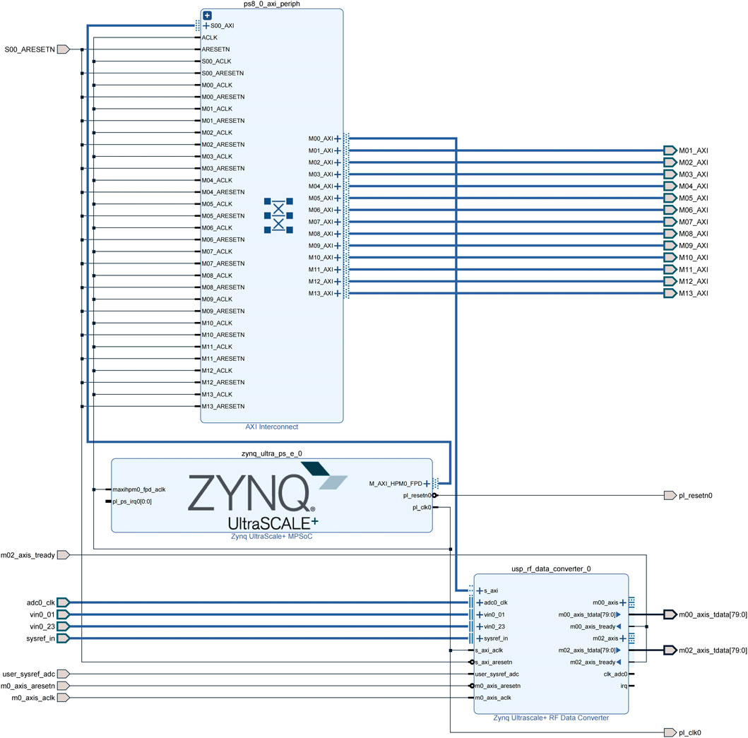
Figure 2. Signal_receive block design.
2.2 Sub-band division
The main difficulty in implementing sub-band division on FPGA is how to deal with the synchronization and switching problem between the high-speed input signal and the low-speed sub-band signal. The solution relies on the critical sampling polyphase filter bank. The algorithm implementation process adopts a pipeline and parallel architecture, which can fully utilize the parallel computing ability of FPGA, improve the operation speed and throughput of the polyphase filter bank, and reduce the hardware resource consumption and power consumption as much as possible. To realize the critical sampling polyphase filter bank in FPGA, it is necessary to design an analysis filter bank. Analysis filter bank includes a commutator and several low-pass filters. According to the Nobel identity, extracting first and then linear filtering is equivalent to linear filtering first and then extracting, as shown in Equation 1, where
This can replace the order of filtering and extraction, and perform
Figure 3 shows the structure diagram of the critical sampling polyphase filter bank, where the red part is the commutator, the blue part is the sub-filter, and the green part is the 20-point parallel DFT.
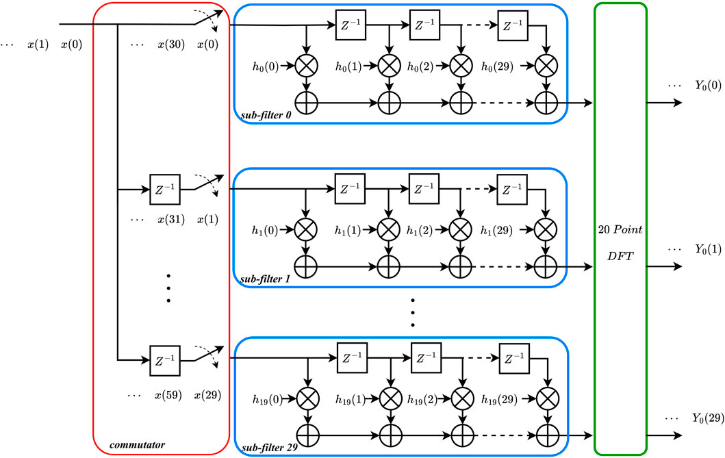
Figure 3. Structure diagram of the critical sampling polyphase filter bank.
Since down-sampling will cause spectrum overlap, it is necessary to low-pass filter the input signal to suppress spectral aliasing and leakage, and eliminate the computation of invalid data. This study designs a finite impulse response low-pass filter based on the Kaiser window function. The advantages of the FIR filter are high stability, linear phase, and easy implementation. Its calculation formula is shown in Eq. 5, where
The Kaiser window is a commonly used window function, which can flexibly adjust the window function parameters to balance the transition bandwidth and side lobe level. The order of the prototype filter is 599, with 600 coefficients. The stopband cutoff frequency is 68 MHz,
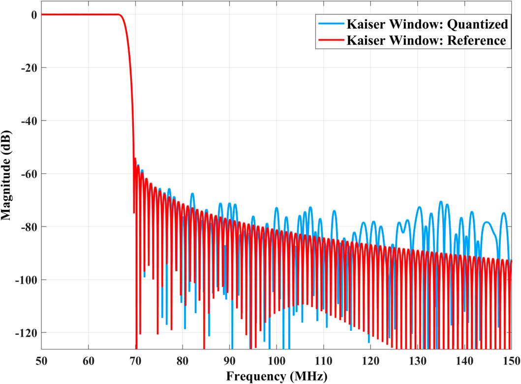
Figure 4. Comparison of the fixed-point quantization amplitude frequency response and the double-precision floating-point reference amplitude frequency response of the Kaiser window.
The filtered data needs to go through the DFT module to obtain a single frequency sub-band carrying the original signal. This study uses Winograd FFT and Discrete Fourier Transform to jointly construct a 20-Point DFT module. WFFT is an efficient algorithm for computing the Discrete Fourier Transform of a signal, which reduces the number of multiplications operations at the cost of increasing the number of addition operations (Winograd, 1978). Due to the parallel structure of the FPGA, it can execute multiple addition operations simultaneously, while the multiplication operations are relatively slow and occupy more resources. The Winograd algorithm optimizes the computational efficiency by minimizing multiplication operations to improve the overall processing speed. Taking the five point WFFT as an example, the five point DFT is expressed in matrix form and converted to a cyclic correlation form. According to the periodicity of the symmetry factor, it is simplified as:
We assume:
Then can get:
Where
The basic principle of the 20-Point DFT module is to decompose it into 4 five-point WFFTS and 5 four-point DFTS using the prime factor method and the Chinese remainder theorem mapping, where four and five are two coprime integers, avoiding the twiddle factors multiplication in the Cooley-Tukey algorithm (Bhagat et al., 2018). Suppose a sequence of length
Where
Then a 2D DFT can be obtained, that is:
In the 20-Point DFT module, the 20 point sequence is decomposed into four five point sequences, and then WFFT is performed on each 5 point sequence to obtain four five point coefficients, and then these coefficients are rearranged into five four point sequences, and then DFT is performed on each 4 point sequence to obtain five four point coefficients, and finally these coefficients are rearranged into a 20 point coefficient, which is the final result. The 5-Point WFFT module and the 4-Point DFT module are implemented separately and combined to obtain the 20-Point DFT module, and its calculation structure is shown in Figure 5.
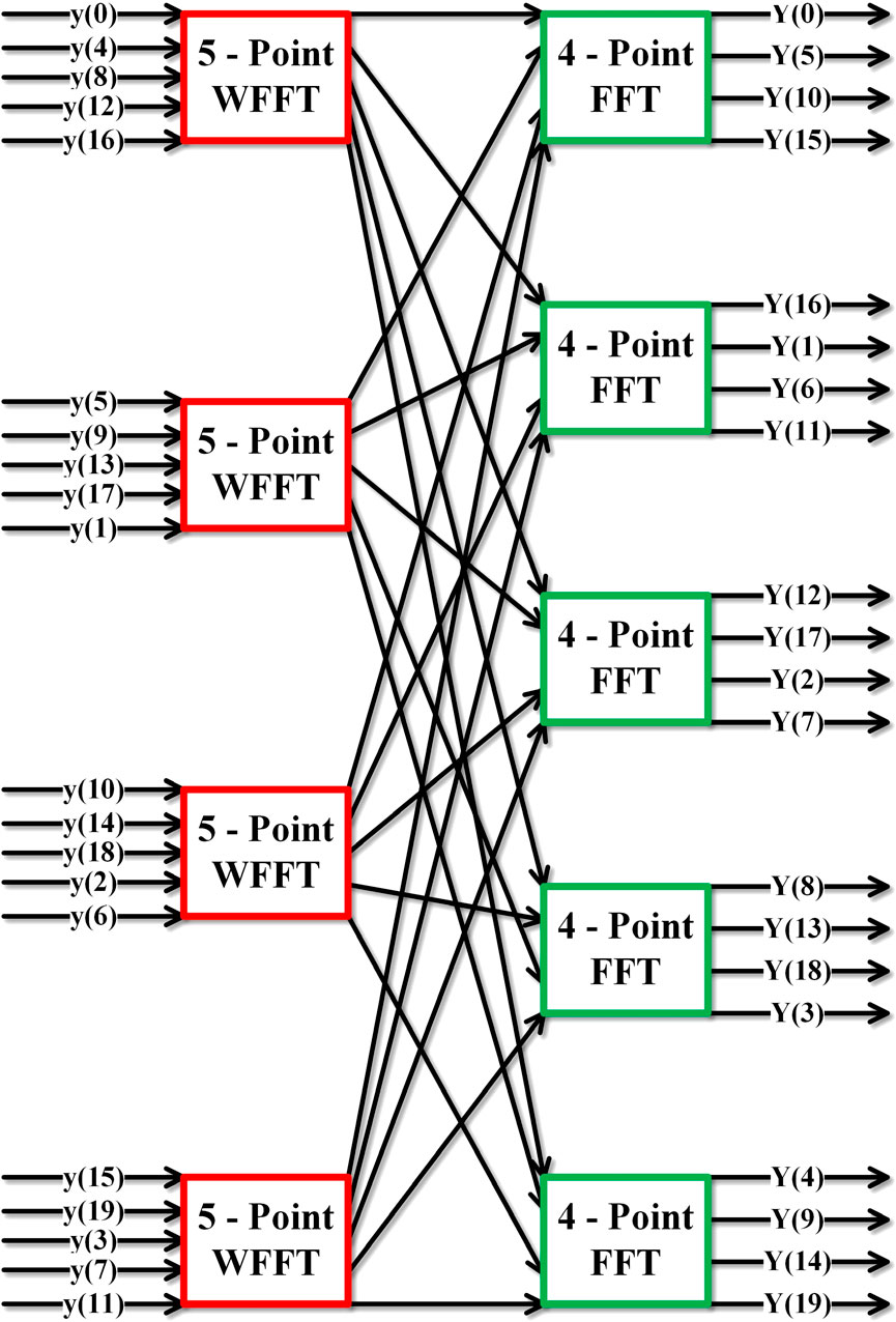
Figure 5. Implementation structure of 20-Point DFT.
In the hardware implementation, the FIR filter uses the FIR Compiler IP core, with 20 sub-FIR filters, each with 30 coefficients. The coefficients are generated by splitting the coefficients of the FIR prototype low-pass filter based on the Kaiser window. The input sample frequency and clock frequency are both 128MHz, the input data width is 12 bits, the coefficient width is 16 bits, and the full precision mode is used. The filtered data is real and needs to be converted to complex form, to prepare the data for the subsequent 20-Point DFT. The Real2complex module written in Verilog is used to take the filtered real signal as the real part of the complex signal, and 0 as the imaginary part of the complex signal. To achieve real-time processing of ultra-wide bandwidth high-speed data streams, a 20-Point DFT module written in Verilog is used, which can realize real-time parallel DFT processing. The output data is conjugate symmetric, and only half of the data needs to be retained. This study uses ZCU111 board, chip model xzcu28dr-ffvg-1517-1-e, developed in Ubuntu 20.04 system. The IP developed by our team include Comutator, Selector, Real2complex, WFT, DFT, Ethernet _ MAC, Ethernet _ VDIF, Datasnapshot and so on. All IP and project have been publicly available on the gitee1 website. PS block design as shown in Figure 6, the RFSoC receives and processes dual-polarization data, and the Polar_a block design of polarization A is shown in Figure 7.
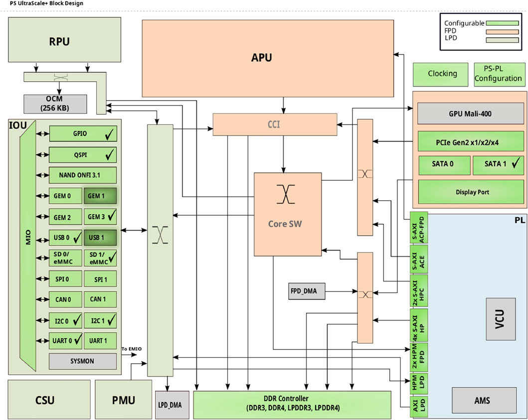
Figure 6. PS block design.
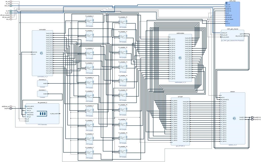
Figure 7. Polar_a block design.
2.3 Data distribution
The data after sub-band division needs to be sent to the GPU for data analysis via Ethernet. Before sending, the sub-band data is encapsulated. The Ethernet transmission of astronomical ultra-wide bandwidth signals not only requires the data packets to be encapsulated in Ethernet frames, but also in the general astronomical format VDIF, which is a standard format for transmitting radio interferometry data. It can support various data types, such as time domain, frequency domain, polarization, etc., and various data transmission methods, such as UDP, TCP, etc. Ethernet frames are protocol data units of the network interface layer, which consist of three parts: frame header, data part, and frame tail. The frame header and tail contain some necessary control information, and the data part contains the data passed down from the upper layer. Different network layer protocols use different frame header formats for identification and processing. The TCP/IP protocol stack model diagram containing VDIF segments is shown in Figure 8.

Figure 8. VDIF/TCP/IP protocol stack model diagram.
The total length of the VDIF frame header in the application layer is 32 bytes, and the length of the data part is 8192 bytes, that is, the total length of the VDIF frame is 8224 bytes. UDP is a connectionless transport layer protocol. The total length of the UDP frame header is 8 bytes, and the length of the data part is 8224 bytes, that is, the total length of the UDP frame is 8232 bytes. The IP frame header in the network layer indicates the source IP address and the destination IP address. The total length of the IP frame header is 20 bytes, and the length of the data part is 8232 bytes, that is, the total length of the IP frame is 8252 bytes. The total length of the Ethernet frame header and tail is 26 bytes, which include preamble, start-of-frame delimiter, destination MAC address, source MAC address, type, frame check sequence, and interframe gap. The length of the data part is 8252 bytes, that is, the total length of the Ethernet frame is 8278 bytes.
In hardware implementation, data encapsulation mainly consists of three modules, namely, VDIF format encapsulation module, Ethernet encapsulation module and local data interaction module. Ethernet_vdif_ch0 is the VDIF format encapsulation module, which encapsulates the astronomical data according to the VDIF protocol and prepares the data for the Ethernet transmission layer. Ethernet_mac is an Ethernet frame encapsulation module, which adds UDP header, IP header, Ethernet header and tail to the VDIF encapsulated data, and adjusts the data format to the XGMII interface standard, preparing the data for the physical layer transmission. The XGMII interface includes an 8-bit xgmii_txc control interface and a 64-bit xgmii_txd data interface. Each bit of the xgmii_txc interface corresponds to one byte of data in the xgmii_txd interface. When it is 1, it indicates that the byte is control information, and when it is 0, it indicates that the byte is data. The sending state transition diagram is shown in Figure 9, where the meanings of the four states are:
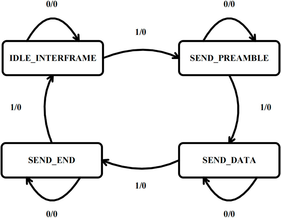
Figure 9. Sending state transition diagram.
IDLE_INTERFRAME: Send interframe gap to ensure that the GPU has enough time to process the previous frame data. The interframe gap is cyclically sent as 0 × 07, and the control interface values are all 1. After receiving the ready-to-send signal from the encapsulation module, it transitions to the SEND_PREAMBLE state.
SEND_PREAMBLE: Send preamble state, send 7 bytes of synchronization code and 1 byte of frame start symbol, and pull up the response signal, and transition to the SEND_DATA state.
SEND_DATA: Send data state, start sending the encapsulated data in byte order, until receiving the end signal, and transition to the SEND_END state.
SEND_END: Send end state, send the last data and 4-byte CRC32 check sequence, check whether the interframe gap is correct, receive the next ready-to-send signal in the IDLE_INTERFRAME state, and jump to the next state.
VDIF_Ctrl is a module that interacts with MPSoC to transfer data. Its function is to read the destination IP, destination MAC, port number, VDIF thread number and other information from the AXI bus of MPSoC, and then transmit them to the VDIF packaging module and Ethernet packaging module through the AXI Stream bus, which facilitates the transmission and control of the information within the frame, and improves the flexibility and compatibility of data transmission. MPSoC IP serves as a logical connection between PS and PL. This study implements the output of four-channel signals with dual polarization, and each channel signal needs to be packaged by VDIF and Ethernet. The Ch0_frame_pack_block design is shown in Figure 10.
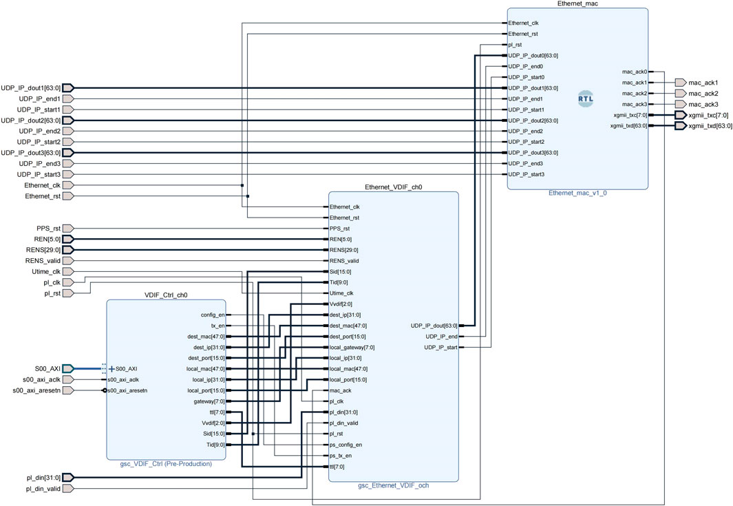
Figure 10. Ch0_frame_pack_block design.
The network card is configured by using the 10G/25G Ethernet Subsystem IP, selecting the Ethernet PCS/PMA 64-bit as the core architecture, processing the MAC separately, 25.78125 Gbps as the line rate, AXI4-Lite as the data interface, BASE-R as the physical layer standard, using optical fiber for transmission, configuring 156.25 MHz as the GT Refclk, selecting 128 MHz as the DRP Clocking, and turning off the FEC Logic, Auto Negotiation and IEEE PTP 1588V2.
After connecting and correctly configuring all the IPs, synthesize and implement the project, burn the bitstream to RFSoC, configure the LMK04208 and LMX2594 clock chips, only turn on CLKOUT0 and CLKOUT3, reduce the power consumption, and perform experimental analysis.
3 Result
3.1 Simulation test result
The algorithm divides the ultra-wide bandwidth data of 64–1344 MHz into 10 sub-bands. Total bandwidth of 1280 MHz and per sub-band width of 128 MHz. They are 64–192, 192–320, 320–448, 448–576, 576–704, 704–832, 832–960, 960–1088, 1088–1216 and 1216–1344 MHz sub-band. Among them, the signals of two sub-bands, 320–448 and 448–576 MHz, are encapsulated and transmitted to the GPU server. To test the effectiveness of the sub-band division, a sweep signal of 320–576 MHz is generated by the signal generator, with a step of 32 MHz, to obtain single-frequency signals of 320, 352, 384, 416, 448, 480, 512, 544, 576 MHz. To avoid the signal being at the edge of the sub-band, the spectrum diagrams of the sub-band division results are plotted when the test signal is at 352, 384, 416 MHz and when the test signal is at 480, 512, 544 MHz. The data is read out from the memory after being divided into sub-bands by the polyphase filter bank. As shown in Figure 11A, when the test signal is in the 320–448 MHz range, the signal falls into the sub-band 0 range and has equal amplitude after the sub-band division. And there is no signal in the sub-band one range, indicating that the signal is effectively divided into sub-bands. As shown in Figure 11B, when the test signal is in the 448–576 MHz range, the signal falls into the sub-band one range and has equal amplitude after the sub-band division, and there is no signal in the sub-band 0 range, indicating that the signal is effectively divided into sub-bands.
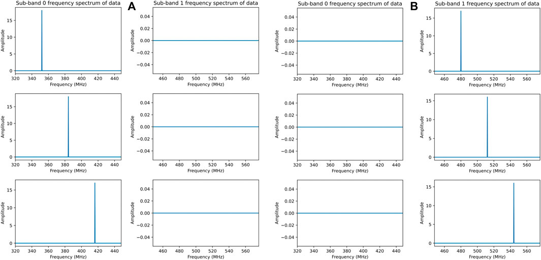
Figure 11. (A) Spectrum diagrams of the sub-band division results when the test signal is at 352, 384, 416 MHz. (B) Spectrum diagrams of the sub-band division results when the test signal is at 480, 512, 544 MHz.
3.2 Actual observation result
We tested the ultra-wide bandwidth signal sub-band division algorithm using the L-band 1 GHz bandwidth receiver of the 26-m radio telescope at Nanshan, Urumqi. By down-converting the Nanshan observation data, we used RFSoC to process 1280 MHz bandwidth data, divided the data into sub-bands, selected and output the 1220–1476 MHz dual-polarization sub-band data, and connected to the GPU server using 4*25G SFP28 to 100G QSFP28 high-speed cables. We used the GPU server to receive the RFSoC sub-band data and plot the spectrum and dynamic spectrum.
We observed the pulsar source J0332 + 5434 for 5 min, and RFSoC divided the observation signal into sub-bands. We used DSPSR to process the received sub-band data, and after removing some channels that were interfered, we obtained the dynamic spectra of sub-band three and sub-band 4 as shown in Figure 12A and Figure 12B, respectively, where clear pulsar profiles can be observed. The dynamic spectrum after sub-band synthesis is shown in Figure 12C, and Figure 12D shows the spectrum of sub-band three and sub-band four merged, where two sub-bands can be clearly seen. The experimental results are consistent with the expectations. Due to the use of critical sampling polyphase filter bank, there will be sideband roll-off phenomenon at the sub-band edge connection, and we plan to improve it by using oversampling polyphase filter bank in the future.
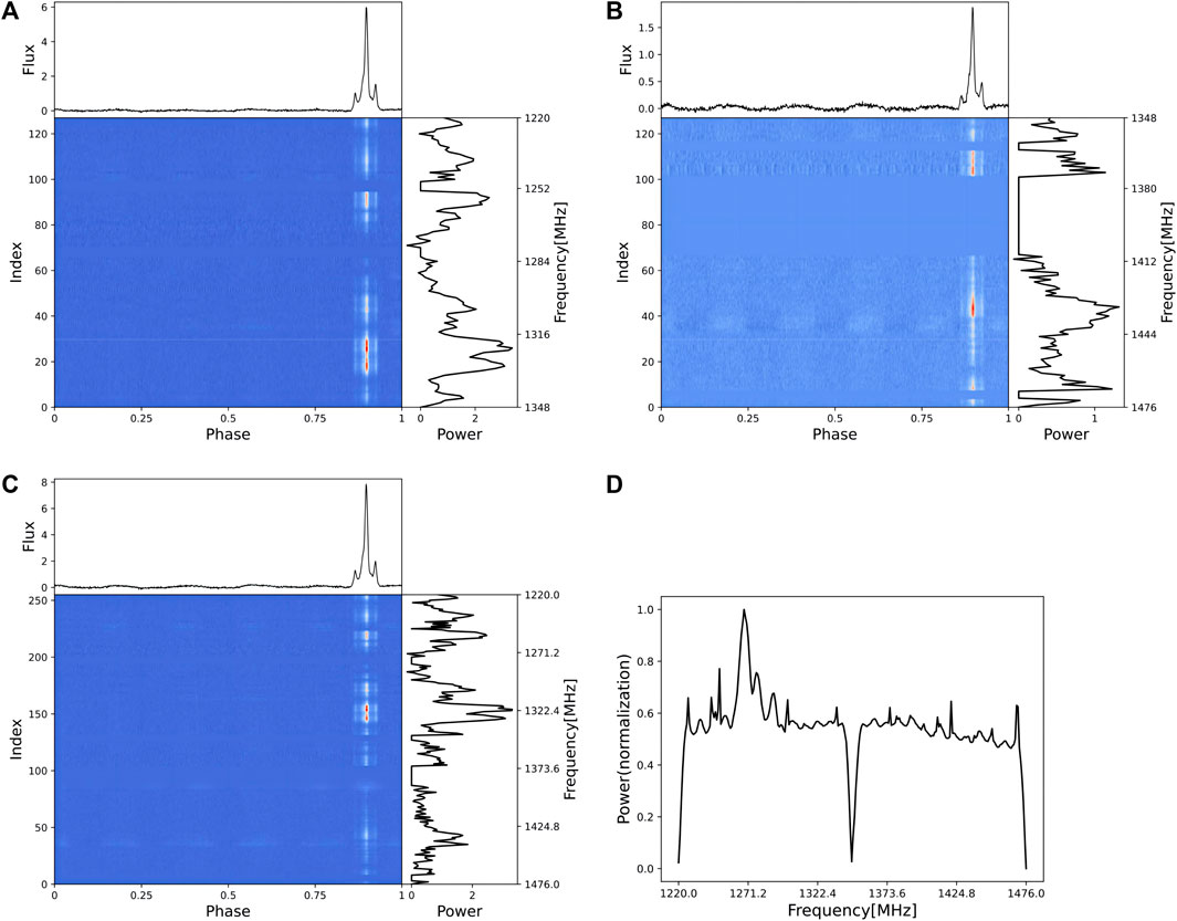
Figure 12. (A) J0332 + 5434 dynamic spectrum of sub-band 3. (B) J0332 + 5434 dynamic spectrum of sub-band 4. (C) J0332 + 5434 dynamic spectrum after merging sub-band three and sub-band 4. (D) J0332 + 5434 spectrum after merging sub-band three and sub-band 4.
By switching the pulsar observation sources, we also observed J1935 + 1616 and J2022 + 2854, and the implemented RFSoC firmware can effectively perform the sub-band division function of astronomical ultra-wide bandwidth signals. The dynamic spectra are shown in Figure 13A and Figure 13B, respectively.
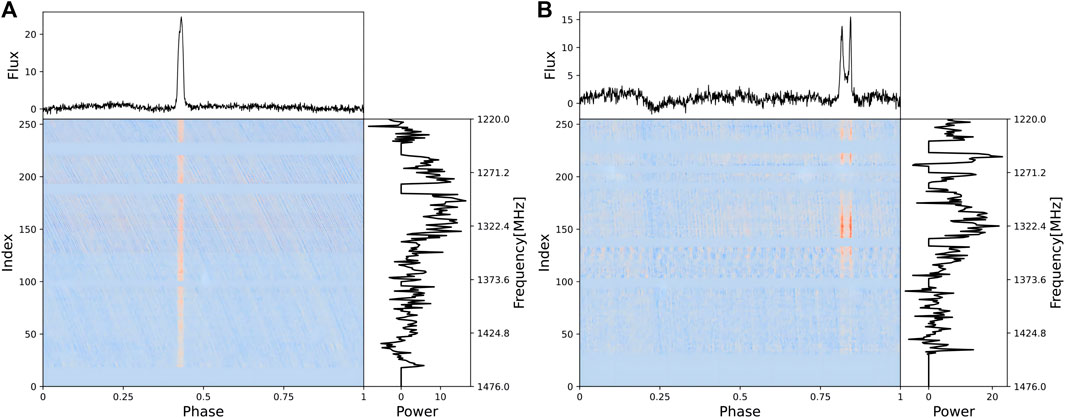
Figure 13. (A) J1935 + 1616 dynamic spectrum after merging sub-band three and sub-band 4. (B) J2022 + 2854 dynamic spectrum after merging sub-band three and sub-band 4.
4 Conclusion
This study presents a sub-band division algorithm for astronomical ultra-wide bandwidth pulsar signals based on RFSoC, which solves the problems of real-time processing and transmission of astronomical ultra-wide bandwidth pulsar signals. The algorithm adopts a filter coefficient design method based on the Kaiser window function, with a FIR filter coefficient of 599 order, the first side lobe attenuation amplitude of −54 db, and uses a 12-bit wide ADC and a clock of 512 MHz, with low spectrum leakage and aliasing, high data accuracy, and fast processing speed. It uses CPFB and improved DFT to channelize the signals, which improves the quality and efficiency of the signals. Then it performs VDIF and Ethernet encapsulation on the signals, which realizes the division and transmission of ultra-wide bandwidth signals. Through simulation tests and actual observations, the feasibility, effectiveness and stability of the algorithm are verified.
Data availability statement
The original contributions presented in the study are included in the article/Supplementary material, further inquiries can be directed to the corresponding author.
Author contributions
XD: Conceptualization, Data curation, Formal Analysis, Funding acquisition, Investigation, Methodology, Project administration, Resources, Software, Supervision, Validation, Visualization, Writing–original draft, Writing–review and editing. H-LZ: Conceptualization, Data curation, Formal Analysis, Funding acquisition, Investigation, Methodology, Project administration, Resources, Software, Supervision, Validation, Visualization, Writing–original draft, Writing–review and editing. S-CG: Conceptualization, Data curation, Formal Analysis, Investigation, Methodology, Project administration, Resources, Software, Validation, Writing–original draft. Y-ZZ: Conceptualization, Data curation, Investigation, Methodology, Project administration, Resources, Validation, Writing–original draft. JL: Conceptualization, Software, Data curation, Methodology, Project administration, Resources, Validation, Writing–original draft. JW: Funding acquisition, Methodology, Project administration, Validation, Writing–original draft, Conceptualization, Investigation. X-CY: Resources, Conceptualization, Investigation, Methodology, Project administration, Validation, Writing–original draft. HW: Conceptualization, Formal Analysis, Methodology, Validation, Writing–review and editing. TZ: Investigation, Resources, Supervision, Validation, Writing–review and editing.
Funding
The author(s) declare financial support was received for the research, authorship, and/or publication of this article. This work is supported by the National Key R&D Program of China No. 2021YFC2203502 and 2022YFF0711502; the National Natural Science Foundation of China (NSFC) (12173077 and 12003062); the Tianshan Innovation Team Plan of Xinjiang Uygur Autonomous Region (2022D14020); the Tianshan Talent Project of Xinjiang Uygur Autonomous Region (2022TSYCCX0095); the Scientific Instrument Developing Project of the Chinese Academy of Sciences, grant No. PTYQ2022YZZD01; China National Astronomical Data Center (NADC); the Operation, Maintenance and Upgrading Fund for Astronomical Telescopes and Facility Instruments, budgeted from the Ministry of Finance of China (MOF) and administrated by the Chinese Academy of Sciences (CAS); Natural Science Foundation of Xinjiang Uygur Autonomous Region (2022D01A360); the Chinese Academy of Sciences (CAS) “Light of West China” Program under No. 2022-XBQNXZ-012.
Acknowledgments
The software and software environment used in the experiment of this paper is from the National Astronomical Observatories of Chinese Academy of Sciences. Thanks to Teacher Ran Duan and his team members for their support and guidance.
Conflict of interest
The authors declare that the research was conducted in the absence of any commercial or financial relationships that could be construed as a potential conflict of interest.
The handling editor (HW) declared a shared parent affiliation with the author(s) (HZ) at the time of review.
Publisher’s note
All claims expressed in this article are solely those of the authors and do not necessarily represent those of their affiliated organizations, or those of the publisher, the editors and the reviewers. Any product that may be evaluated in this article, or claim that may be made by its manufacturer, is not guaranteed or endorsed by the publisher.
Footnotes
1https://gitee.com/WhataDavid/cspfb_on_rfsoc
References
An, X. M., Chen, M. Z., Pei, X., Li, J., and Duan, X. F. (2021). High-speed baseband data recording system for radar astronomy research. Acta Astron. Sin. 62 (5), 51. doi:10.15940/j.cnki.0001-5245.2021.05.005
Arnaldi, L. H. (2020). “Implementation of a polyphase filter bank channelizer on a ZYNQ FPGA,” in 2020 Argentine Conference on Electronics (CAE), Buenos Aires, Argentina, 27-28 February 2020 (IEEE), 57–62. doi:10.1109/CAE48787.2020.9046377
Bhagat, N., Valencia, D., Alimohammad, A., and Harris, F. (2018). High-throughput and compact FFT architectures using the Good–Thomas and Winograd algorithms. IET Commun. 12 (8), 1011–1018. doi:10.1049/iet-com.2017.0837
Curyło, M., Pennucci, T. T., Bailes, M., Bhat, N. R., Cameron, A. D., Dai, S., et al. (2023). Wide-band timing of the Parkes pulsar timing array UWL data. Astrophysical J. 944 (2), 128. doi:10.3847/1538-4357/aca535
Farley, B., Erdmann, C., Vaz, B., McGrath, J., Cullen, E., Verbruggen, B., et al. (2017). “A programmable RFSoC in 16nm FinFET technology for wideband communications,” in 2017 IEEE Asian Solid-State Circuits Conference (A-SSCC), Seoul, Korea (South), 06-08 November 2017 (IEEE), 1–4. doi:10.1109/ASSCC.2017.8240201
Hobbs, G., Manchester, R. N., Dunning, A., Jameson, A., Roberts, P., George, D., et al. (2020). An ultra-wide bandwidth (704 to 4 032 MHz) receiver for the Parkes radio telescope, 37. Australia: Publications of the Astronomical Society of Australia, e012. doi:10.1017/pasa.2020.2
Kettenis, M., Phillips, C., Sekido, M., and Whitney, A. (2008). VLBI data Interchange format (VDIF) specification.
Podder, P., Khan, T. Z., Khan, M. H., and Rahman, M. M. (2014). Comparative performance analysis of hamming, hanning and blackman window. Int. J. Comput. Appl. 96 (18), 1–7. doi:10.5120/16891-6927
Tohtonur, H. L., and Zhang, J. W. (2017). A design of polyphase filter bank for radio astronomy based on CUDA. Astronomical Res. Technol. 14 (1), 117–123. doi:10.14005/j.cnki.issn1672-7673.20160518.003
Wang, N., Xu, Q., Ma, J., Liu, Z., Liu, Q., Zhang, H., et al. (2023). The Qitai radio telescope. Sci. China Phys. Mech. Astronomy 66 (8), 289512. doi:10.1007/s11433-023-2131-1
Winograd, S. (1978). On computing the discrete Fourier transform. Math. Comput. 32 (141), 175–199. doi:10.2307/2006266
Zhang, H. L., Zhang, M., Zhang, Y. Z., Wang, J., Ye, X. C., Wang, W. Q., et al. (2023b). Channelization of wideband signal based on critical sampling polyphase filter banks. J. Jilin Univ. Eng. Technol. Ed. 53 (8), 2388–2394. doi:10.13229/j.cnki.jdxbgxb.20220274
Zhang, H. L., Zhang, Y. Z., Zhang, M., Wang, J., Li, J., Ye, X. C., et al. (2023a). Research on ultra-wide bandwidth low-frequency signal channelization for Xinjiang 110 m radio telescope. Res. Astronomy Astrophysics 23 (12), 125023. doi:10.1088/1674-4527/ad0427
Keywords: rfsoc, ultra-wide bandwidth signal, sub-band division, parallel processing, fourier transform
Citation: Du X, Zhang H-L, Guo S-C, Zhang Y-Z, Li J, Wang J, Ye X-C, Wu H and Zhang T (2024) A sub-band division algorithm for ultra-wide bandwidth pulsar signals based on RFSoC. Front. Astron. Space Sci. 11:1391070. doi: 10.3389/fspas.2024.1391070
Received: 24 February 2024; Accepted: 29 March 2024;
Published: 10 April 2024.
Edited by:
Hairen Wang, Chinese Academy of Sciences (CAS), ChinaReviewed by:
Carlos Frajuca, Federal University of Rio Grande, BrazilFeng Wang, Guangzhou University, China
Jun Nie, University of Science and Technology of China, China
Copyright © 2024 Du, Zhang, Guo, Zhang, Li, Wang, Ye, Wu and Zhang. This is an open-access article distributed under the terms of the Creative Commons Attribution License (CC BY). The use, distribution or reproduction in other forums is permitted, provided the original author(s) and the copyright owner(s) are credited and that the original publication in this journal is cited, in accordance with accepted academic practice. No use, distribution or reproduction is permitted which does not comply with these terms.
*Correspondence: Hai-Long Zhang, emhhbmdoYWlsb25nQHhhby5hYy5jbg==