 Zhi-Yue Wang1
 Guang-Yu Zhang1Jian Wang1,2*Zhe Geng1
 Ze-Yu Zhu1Ming-Hao Jia1Qian Zhang1Zhen-Hao Zheng2Kun Ge1Jia-Yao Gu2Lu-Cheng Zhu2Hong-Fei Zhang1
- 1Deep Space Exploration Laboratory, State Key Laboratory of Particle Detection and Electronics, Department of Modern Physics, University of Science and Technology of China, Hefei, China
- 2Institue of Advanced Technology, University of Science and Technology of China, Hefei, China
With the increasing demand for astronomical observations, telescope systems are becoming increasingly complex. Thus, the observatory control software needs to be more intelligent. It has to control each instrument inside the observatory, finish the observational tasks autonomously, and report the information to users if needed. We developed a distributed autonomous observatory control framework named the Remote Autonomous Control System 2nd (RACS2) to meet these requirements. Rich features are integrated into the RACS2 framework. The RACS2 is a modular framework, in which each device control software and system services are implemented as different components. Furthermore, the RACS2 framework assimilates new techniques, such as a lightweight message and serialization mechanism. RACS2 also has good compatibility with other frameworks or ecosystems such as Python and the EPICS (Experimental Physics and Industrial Control System). The RACS2 framework can communicate with EPICS-based and Python-based software. With the help of these features, key system components like executor, scheduler are developed. The executor component can support sophisticated tasks. Autonomous observation can be achieved by the scheduler component. A set of web-based graphical user interface (GUI) is designed to help control and manage the framework remotely. Based on the RACS2 framework, we have implemented the Dome A Twins (DATs) telescope’s observation system and the space object observation system. The systems have been operated for more than 1 year. The RACS2 framework also has been used in our other projects like camera control system of Wide Field Survey Telescope (WFST) and its observatory control system, and the design can be a useful reference for the development of other frameworks.
1 Introduction
Astronomical telescopes have undergone great changes since they were first invented in the 17th century. Modern large-aperture astronomical telescopes are large scientific systems consisting of many subsystems, such as optical systems, camera systems, telescope mounts, domes, weather stations and even adaptive optics or active optics systems. On the other hand, since various environmental factors (i.e., climate, light pollution, number of clear nights and air turbulence) will affect the observation, candidate sites are often selected at plateaus, mountains or Antarctica for better imaging quality and higher observation efficiency. Many of these sites are far from cities and are not suitable for human survival. Therefore, the remote-control feature needs to be added to observatory control systems.
Many of these remote sites have extremely poor network conditions, i.e., Antarctic observatories. For these observatories, remote operation often suffers from very long network delay. Network delay causes two kinds of problems: first, the emergency events, i.e., weather changes, require the control system to react as quickly as possible, and network delay makes the response of control system very slow and unable to meet the requirements. The second problem is that the observation task itself may become slow due to the network delay if the observatory is controlled totally remotely. Therefore, the control systems of these observatories must obtain some kind of automatic/robotic control mechanism, to avoid frequently communication between sites and users, and react to emergency events quickly.
According to the concept of robotic autonomous observatories introduced by A.J. Castro-Tirado (Castro-Tirado, 2010), telescope systems are categorized into four levels by the degree of automation. 1. Automated Scheduled Telescopes, 2. Remotely Operated Telescopes, 3. Autonomous Robotic Observatories (ARO), and 4. Robotic Autonomous Observatory Networks (RAO). According to this classification, many observatories are between ARO and RAO. They can achieve some level of robotic observation, such as selecting the next observation target according to plans, changing the observation state according to sensor information and weather, or sending notification to operators while automatically changing the observation state. As the conclusion of this paper, robotic astronomical networks will become the main stream in the near future.
Another feature of the control system of modern observatories is that they are normally distributed systems. Basic observatories can be controlled by a single computer. Therefore, the status synchronization and management of control flow is rather simple. But for large telescopes, most components are very sophisticated. A single-node system doesn’t have enough calculation and storage resources to run all these components simultaneously. Therefore, distributed architectures are needed for large automatic telescopes. Each of the components is a separate program running on different nodes. As shown in Figure 1 (Wang et al., 2013a), the control software of a typical modern large observatory consists of 5 subsystems, the Telescope Control System (TCS), the Instrumentation Control System (ICS), the Observation Control System (OCS), the Data Handling System (DHS), and the User Interface (UI). The OCS is the center of the control system, and it manages the resources and schedules of the whole telescope. The OCS is the top layer of the control system and other subsystems. The TCS controls the telescope mount to point, track, and calibrate, and it also controls the telescope focuser system. For more sophisticated optical telescopes that are equipped with an Adaptive Optics System or an Active Optics System, the TCS also needs to control these systems. The ICS controls the focal plane instruments, including cameras, spectrometers, filters, shutters, focusers, and diffusers. The DHS stores the data and provides corresponding access interfaces.
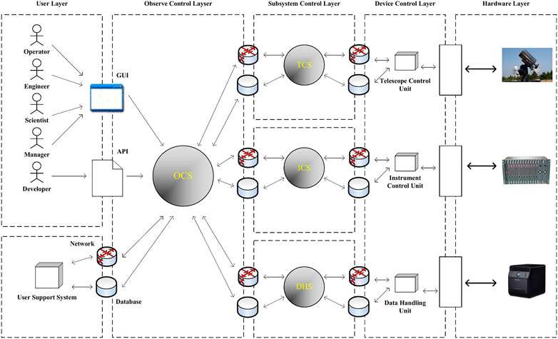
FIGURE 1. Telescope observational and control system framework.
Modern observatories adopt various architecture and techniques to implement their control systems. In order to achieve efficient and reliable communication between components, different communication libraries are used. And these control systems develop their abstract layers of instruments and control flows, respectively, so that the observation task and instrument management can be accessed via consistent interfaces. For large observatories, the control systems, including the frameworks, the control flows and the interfaces are often dedicated.
For example, the Keck telescope built its original control system in 1994 as introduced in (Lupton et al., 1994), which used the TCP/IP communication and a set of custom workflow control library, referred to as the Keck Task Library (KTL). In 2013, the control system of Keck telescope has undergone an upgrade (Johnson et al., 2013), the new system uses a customized EPICS Channel Access as the communication middleware to maintain backward compatibility towards the original EPICS device modules. For workflows control and task management, the original Keck Task Library remains usable.
The Large Sky Area Multi-Object Fiber Spectroscopic Telescope (LAMOST)’s control system is built based on the Common Object Request Broker Architecture (CORBA), and the communication mechanism is the one implemented in the ACE ORB(TAO) (Wang et al., 2006).
The Vera Rubin Observatory, also known as the Large Synoptic Survey Telescope (LSST), has a control system which uses a Data Distribution Service (DDS) based communication middleware (Mills et al., 2016; Schumacher et al., 2006). One of the reasons for using the DDS, as mentioned in Schumacher (Schumacher et al., 2006), is that the publisher/subscriber architecture and event-based communication model allows the program to communicate anonymously, which is suitable for large systems.
The Square Kilometre Array (SKA)’s observation control framework (Williams et al., 2016) is built based on TANGO control framework (Gotz et al., 2009), which uses the CORBA technique.
The Atacama Large Millimeter/Submillimeter Array (ALMA) also uses a CORBA bases control framework (Chiozzi et al., 2002), and the communication is achieved by the DDS middleware (Caproni et al., 2016).
The Thirty Meter Telescope (TMT)’s control system has a communication service named Connection and Command Service, which is a communication middleware based on the AKKA (Roestenburg et al., 2016), which is a library implemented the actor model (Agha, 1986). The observation control framework of the TMT is still under construction (Gillies et al., 2020; Dunn et al., 2006).
In conclusion, the control systems of large observatories, are often dedicated, since their workflows and hardware systems are often unique. Some general-purpose techniques such as the CORBA might be used as the fundamental of control system, but higher-level encapsulations of observatories’ workflows are inevitable. Our laboratory has used some of the communication libraries and observation control mechanisms mentioned above, as introduced in (Wang et al., 2006; Wang et al., 2013b: Zhang et al., 2016) respectively.
For small telescopes, general-purpose control frameworks, such as the Remote Telescope System, 2nd version (RTS2) (Kubánek et al., 2006) are popular. The RTS2 is developed for the Linux platform. The RTS2 uses a set of its own communication protocol (RTS2 protocol) to interchange commands between components and execute the corresponding task accordingly (Kubánek et al., 2008). It employs a centralized architecture: a service referred to as CentralD provides functions such as naming service and node status monitoring. The CentralD is the key service of the whole system. We used the RTS2 to build the control system of small aperture telescope in Antarctica (Zhang et al., 2016).
Although the RTS2 is widely used, it has some drawbacks and limitations. Extending the RTS2 is very difficult. Users must climb a very steep learning curve to understand the RTS2 class inheritance mechanism, and all the extension codes must be written in C/C++. Other programming languages are not supported. Furthermore, the RTS2 must maintain the CentralD service, if the CentralD service fails, so will the whole system. This can be a large problem for complex telescope systems since distributed systems may encounter partial failure. When such failure occurs (such as the CentralD crashed and other service remain intact), we hope the rest of the system can remain useable with some basic functions, and the RTS2 cannot achieve such a goal. Since the RTS2 is maintained by individual, the maintenance of the RTS2 is discontinued since 2018.
To solve these drawbacks, the Remote Autonomous Control System 2nd, RACS2, is designed and developed. The RACS2 is scalable for different telescope systems, from small amateur telescope systems to large scientific telescope systems consisting of subsystems. The communication mechanism of the RACS2 is implemented based on the lightweight message library ZeroMQ. Control messages are serialized into binary stream with the Protobuf. The communication library is fast and lightweighted, the typical end-to-end delay (including serialization and deserialization) between the RACS2 components is as low as hundreds of microseconds. As for the architecture, the abstract of telescope, camera, and other commonly used instruments are provided. User can implement the support for new devices by writing a simple wrapper. The observation tasks and instrument control utilities are fully decoupled, and the observation tasks can be dynamically scheduled. The RACS2 executor component allow users to use different ways to describe the observation tasks, observation task scripts from other frameworks can be ported to the RACS2 by writing adapters. The RACS2 can be deployed on most Linux and Unix distributions, and the binary release is available as a 10 MB zip file. The RACS2 also provides interfaces towards multiple programming languages (including Python) and other frameworks. The interfaces of RACS2 are easy to understand. A http webserver is built, so that users can control the system remotely via a web-based GUI or http APIs. These features speed up the development of the control systems and help users to further extend the control systems.
2 System architecture
2.1 Layer of observation network and RACS2
Modern astronomical observation systems, such as the Stellar Observations Network Group, SONG (Zheng-Zhou et al., 2018), and the SiTian project (Liu et al., 2021), have shifted from single telescope to telescope networks. The typical software system architecture of such an observatory network is shown in Figure 2. The control framework is divided into two parts: the control system of a single observatory (abbreviated as the observation node, as shown in the right part of the Figure 2) and the managing platform (as shown in the left part of the Figure 2). Each observation node can be further decomposed into three layers:
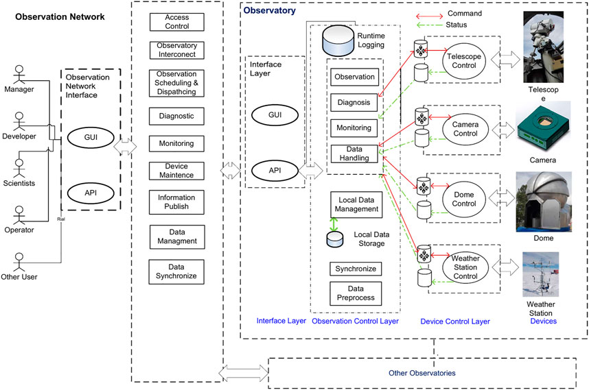
FIGURE 2. System architecture.
Layer 1 Device/data source control layer. This layer interacts with hardware directly and encapsulates the details of the low-level operation.
Layer 2 Observation control and service coordination layer. This layer will interact with Layer 1, and it will implement functions such as observation task execution, data collection, log analysis and system diagnosis, data processing, etc.
Layer 3 Interface layer. This layer provides a graphical user interface (GUI) and an application programming interface (API). The managing platform will interact with the observation nodes via the interfaces provided by this layer. Human users can also use the GUI provided by this layer.
The managing platform gathers information of nodes and sends observation tasks to each node of the observation network. The managing platform will analyze the data and store data into databases. The managing platform provides UIs for the user to interact with it.
The RACS2 focuses on distributed control in a single telescope observatory. It draws the experience from frameworks such as the RTS2 and EPICS and assimilates the idea of decentralization and component auto discovery. A lightweight communication library is used by the RACS2, and the framework specifies the remote procedure call (RPC) interfaces between components. The RACS2 framework uses a layered architecture, as shown in Figure 3. The system consists of two layers: the RACS2 Common Lib and RACS2 Components.
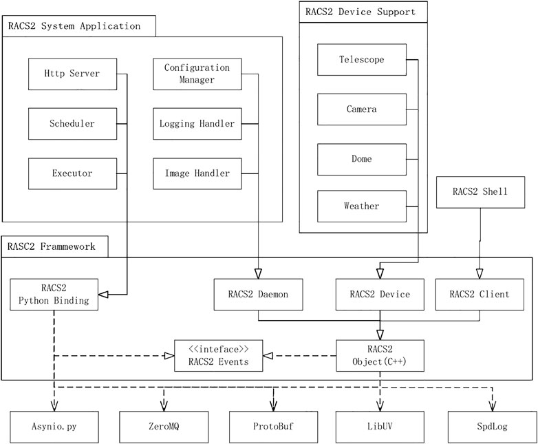
FIGURE 3. Conceptual classes of the RACS2 framework.
The RACS2 Common Lib is a C++ library that implements the basic functions and interfaces of RACS2. All RACS2 components are developed based on the RACS2 Common Lib. The RACS2 components consist of device components and service components. Each of the components is an independent executable program. Together, they make up a network of components. This scheme allows components to run on different devices in a local area network, such as embedded industrial computers of large telescopes, which makes the development of a control system easier.
2.2 RACS2 message mechanism
The Message Bus of RACS2 is shown in Figure 4.
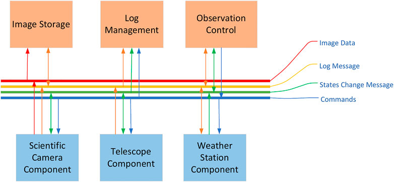
FIGURE 4. The RACS2 message bus.
The message bus of RACS is implemented based on the ZeroMQ (Hintjens, 2013) and Google Protocol Buffer (ProtoBuf) (Google Protocol Buffers Protobuf, 2015). The RACS2 implements an event-driven mechanism based on the libUV (Marathe, 2015). Inside the event loop, it uses the encapsulated socket interface provided by the ZeroMQ to communicate between components. Both the peer-to-peer mode and broadcast mode are implemented. Message serialization and deserialization are performed by the ProtoBuf. The RACS2 provides fine-grained grouping strategies to manage these components. By default, all the components will enter a main group, inside which the state change messages of each component will be broadcast, and the user can organize components with custom groups.
The local area network component discovery mechanism is implemented with beacon mode. Figure 5 shows an example: Component 2 starts at T0, and it broadcasts its IP address and the ZeroMQ Port. An already started component, Component1, captures this message and tries to establish a connection with Component2. At T1, a connection between Component 1 and Component 2 is successfully established, and these components send HELLO messages to each other. Upon receiving the HELLO message, the component replies an INFO message. Inside the INFO message, the metadata consist of the component’s name, type, network address, properties, etc. When receiving the INFO messages, the component will append the information to its peer_list (further described in Section 2.3). By time T2, this entire procedure is finished, and both components are aware of each other. Such procedures can happen between the newcomer component and other components.
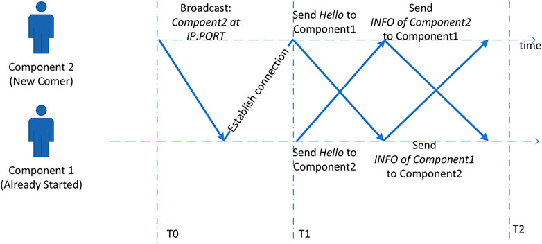
FIGURE 5. Diagram of the component discovery mechanism.
This mechanism improves the scalability of the system and makes it possible to expand the system online without modifying the code and configuration files. Compared with the architecture of polling each node by the central node, the decentralized architecture saves network traffic and resources.
In the observational system, each instrument or observation service is abstracted into a RACS2 component, and each property of the component maps to the corresponding attribute of the instrument. When a user changes the property, the framework will operate the hardware or call some software function. Such operations are performed by sending messages to the component. Each message contains type information in the header, and there are three types of messages:
1 ChangeProperty messages and PropertyChanged messages identify the operations toward the Property of components. It includes the name of the Property and its target value. When receiving ChangeProperty messages, the component will normally trigger some corresponding procedures, such as operation toward an instrument or a software function, and broadcast a PropertyChanged message to notify other components that the procedure is finished. Figure 6 shows an example: the target RA and DEC of a telescope mount are abstracted into RA Property and DEC Property, respectively, so when users want to point some certain sky area, they can send a ChangeProtperty message to the telescope mount component, and the component will do the underlying job, such as sending a command via a serial port. When the mount pointing is completed, the telescope mount component will broadcast a PropertyChanged message to every component in the group.
2 Log messages contain some log information. The log service captures these messages and records them.
3 Command messages can be used to trigger some complicated procedures. A command message contains a command name and some arguments. For example, the initialization procedure of a scientific camera contains many arguments, such as readout speed, gain level, cooling configuration and so on, and the user can define a command message to handle it. Sometimes, the same work can be done with a group of property messages, but a command message is simpler and more intuitive.
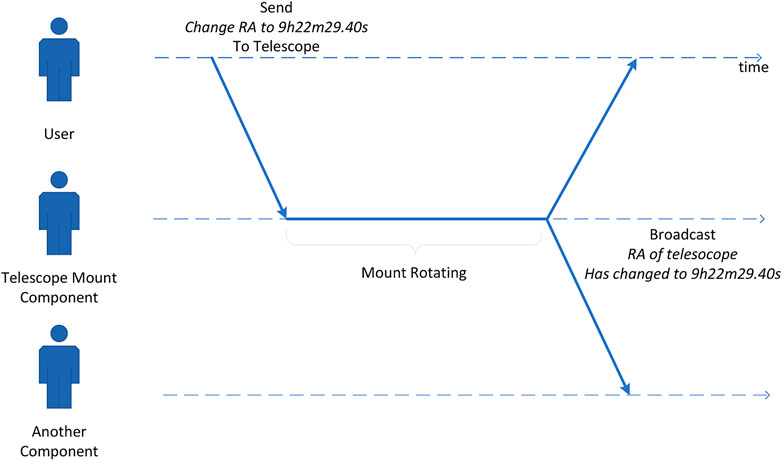
FIGURE 6. An example of the message sequence when change a property.
The message typing system facilitates the development of system service components, such as logger, executor and scheduler. Unlike many frameworks which use message system based on message broker, the message mechanism of the RACS2 is simple and lightweighted, a standalone message service is not needed, thus help the deployment of the system.
2.3 RACS2 classes and events
The RACS2 is designed following the object-oriented paradigm. Users can directly inherit Daemon and Client classes to implement their own components. For some even more special requirements, users can inherit Network, Logger, and other tool classes. This design enhances the scalability of the system. Figure 7 is the class diagram of the RACS2 framework. As the figure shows, EventCallback, Daemon and Client are the base classes used by other classes, and the derived classes are the tool classes mainly used to realize specific functions.
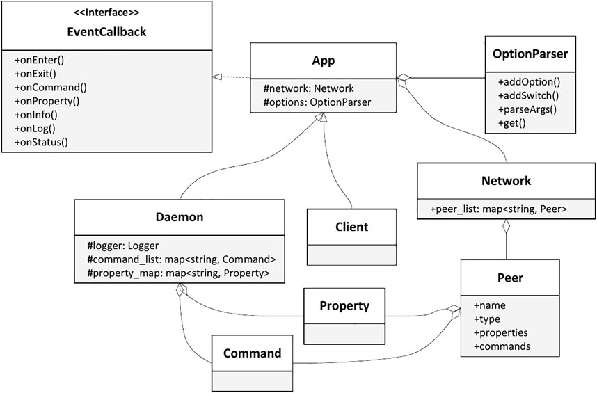
FIGURE 7. Class diagram of the RACS2 framework.
Event-driven is a key feature of RACS2, and the event interfaces are defined by the EventCallback class. Each interface of EventCallback corresponds to an event type. The derived classes do not need to implement all event interfaces. Since these interfaces are merely a CPP function, the user can call them manually and check the result, so the unit test for each derived class can be implemented easily (compared with some complicated RPC call).
The event loop of RACS2 is built based on the libUV framework. With the event loop, the callback functions mentioned above will be triggered when the corresponding event occurs. onEnter, onJoin, and onExit handle the component entering and leaving procedures as we described in Section 2.2. Message handling is likewise, when a message is received, the component will read the header of the message to indicate its type and call onCommand, onLog or onProperty to process Command, Log, and ChangeProperty messages, respectively.
To avoid confusion, a naming convention has to be clarified before any further description. The RACS2 documentation uses word component, while the code list uses the word peer. These two words are of the same meaning in the RACS2 framework and are interchangeable. Each component holds a peer_list to record every component in the network. The structure of peer_list is shown in Figure 8. As shown in the figure, the peer_list is an indexed data structure that records the information of every known component. The index of peer_list is the UUID of the corresponding component. Recorded information includes the value and metadata of each property, the available command, and other metadata (such as IP address and port). When the component receives a PropertyChanged message, it updates the value recorded in peer_list. As described in Section 2.2, the peer_list is updated every time components enter or leave the network. By storing the value of properties inside peer_list, the component can access these values without querying them from the network and therefore save some network traffic.
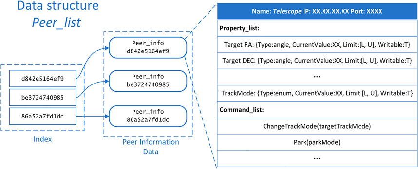
FIGURE 8. The peer_list data structure.
2.4 Configuration management
The configuration management of RACS2 is based on configuration files. The RACS2 configuration management system has the function of searching, loading, and automatically updating the configuration files. Each component maps to a configuration file named after the component name. In addition, there are independent configuration files, such as the EPICS component mapping file, database configuration file, the FITS header mapping file and site information.
The RACS2 provides a tool class called ConfManager. The structure of the configuration of RACS2 is shown in Figure 9. Configuration data are grouped into several profiles, and inside each profile are many key-value pairs. The ConfManager will read the configuration files stored in the file system (by default, the path is/etc.,.tc/racs2 for the Linux system) and load all the key-value pairs recorded in these files. After the initialization, components can access each configuration item by its profile and key name from the ConfManager. The ConfManager also allows components to update certain configuration item and store the new value into the configuration file.
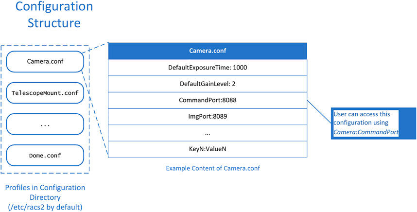
FIGURE 9. Structure of configuration files.
A typical usage of the ConfManager is to store the choice of FITS (Grosbøl, 1991) headers. FITS headers are often used to record many important metadata, such as exposure time and gain level, into image data files. For some custom observation tasks, scientists may want to use some custom FITS headers. We use the ConfManager to implement such a function: all the needed FITS headers are stored in a configuration file. The ConfManager will load this file and read the configuration items from it. When the camera component has finished an exposure task and creates the FITS file, it will ask the ConfManager about which custom headers are needed and where to find their values (normally from other components) and then write these FITS headers.
2.5 Programming interface
We developed a set of Python binding named Pyles, and users can implement the RACS2 component in Python with Pyles. The Pyles is implemented based on the C++ Pybind11 library. The bound interfaces include the following C++ types: EventCallback, Peer, Property, Network, and ProtoBuf types. In the implementation of pyles, event loop is implemented with asyncio library. Asyncio provides asynchronous I/O operation, system signal control, idle work and other functions in Python components. In addition, asyncio also provides support for Python coroutines. The log class is implemented based on Python’s logging module. It is compatible with the C + + version of the log class and will also automatically send logs to the message bus. Python is suitable for rapid development. Therefore, many RACS2 components are implemented based on Python language with Pyles, such as the log service, the executor and the diagnostic system.
Another interface is the EPICS bridge. Since we have developed many control software programs based on the EPICS, we want to make use of these software programs. The EPICS bridge is a protocol parser, it listens to the message queue of the RACS2, interprets the message to the EPICS Channel-Access, and interprets the CA message to the ZeroMQ message queue of RACS2. With the EPICS bridge, EPICS IOCs can be accessed from the RACS2 components.
Interfaces to other frameworks, such as web server or stream processing systems can be implemented based on Pyles and the corresponding python clients, thus improves the compatibility of the RACS2 framework.
3 RACS2 system components
To make the RACS2 available for more users, we have performed much work on interface adapting, user GUI and automatic scheduling.
3.1 Observation control and service coordination
Automatic observation is a key feature of an automatic observation control system, it is usually divided into two parts: the plan dispatcher and the command executor.
To avoid confusion, the terminology plan and script need to be introduced here. In the following paragraphs, the word script means literally a script, it is the definition of a sequence of operations. The word plan means an actual observation task to do, many observatories may use the word proposal to describe such thing. For the RACS2 framework, different plans may share a same script if they perform some similar tasks.
In many observation frameworks, the design of automatic observation is often not flexible enough to meet the requirements of complex telescope applications. For example, the RTS2 has a set of finite state machines to implement automatic observation. Xml files are used to describe the observation tasks, each xml file contains several entries, each of which represents a plan. Each entry includes target objects information, time of observation, and other miscellaneous information. The RTS2 executor will follow the xml file to perform the observation. Regardless, it is difficult for human users to write and read xml files, and only the sequential observations are supported. Users have to change the code to implement more powerful features, such as automatically find the next target to observe. We want to solve these drawbacks by introducing a set of more powerful observation executing mechanisms into the RACS2.
Instead of using configuration files to record observation plans, the RACS2 uses Python scripts to describe observation plans. Inside the observation scripts, the user can access every component in the network with the RACS2 python interface. Python language intrinsic features are supported in observation scripts. For example, async and await are usable, so the user can perform asynchronous waiting in the script. For safety considerations, we will check the import functions. Compared to xml files, Python scripts can describe much more complicated procedures, including judging and branching. Users can even use the python mathematic libraries (such as numpy) and database interfaces (such as ORM) inside the script.
For simple observations, such as repeatedly pointing to some sky area, starting tracking and taking pictures, the RACS2 also provides some helpful utilities. Users can specify arguments for the script by uploading CSV files with lists of arguments. The RACS2 executor will automatically execute the script with each set of arguments in the CSV file.
# Acquire the parameters
ra = float (args [0])
dec = float (args [1])
exptime = float (args [2])
# Acquire the components
cam = racs2.get_peer (“CAM”)
tel = racs2.get_peer (“TEL”)
# Set the properties of each component
racs2.setprop (cam,“EXPTIM”, exptime)
racs2.setprop (tel,“TargetR”, ra)
racs2.setprop (tel,“TargetDE”, dec)
# Tell the telescope to move to the position
racs2.sendcmd (tel,“mov”)
# Wait until the telescope points to the position and starts tracking, with a timeout of 30 s
await racs2.wait_status (tel, “IDL”, 30)
# Send exposure command, at the same time the telescope is tracking the object
racs2.sendcmd (cam,“expos”)
# Wait until the exposure finish
await racs2.wait_status (cam,“IDL”, exptime+30)
The list above is a typical observation script used in the DomeA Twins (DATs) project. This script shows features of RACS2 observation scripts. At the beginning of the list is arguments capturing. ra, dec, and exptime (exposure time) are the arguments passed to the script. The RACS2 python library is injected into the context at the beginning. With racs2.setprop, the user can set the property of another component, and with racs2.sendcmd, the user can send a command to another component. The racs2.wait_status function allows the user to asynchronously wait for a condition to satisfy before continuing execution.
The scripts are stored inside an observation database. The schema of the observation database is shown in Figure 10. Each observation plan is recorded in a plan table. Every plan has a script_id that points to the observation script it uses, as well as the parameters that are stored in the plan_args table. The executor will check the validity of the parameters at runtime according to the information in the script_args table.
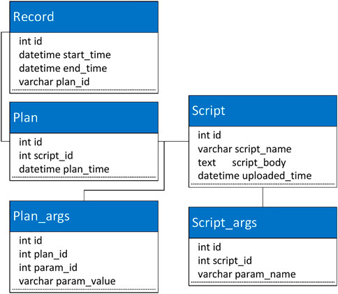
FIGURE 10. Database schema of the observation database of RACS2.
The RACS2 uses two system components to conduct the observation: the scheduler component and the executor component.
The scheduler component analyzes the observation plans in the database to select the next plan to execute, which will sent to the executor then. When the observation plan is complete, the executor will broadcast this event, so that the scheduler can sent the next plane to it.
There are two default scheduling mechanisms, sequential or repeat. For the sequential mode, plans are ordered by their desired start time, and are sent to executor under this order. For the repeat mode, the same plan will be sent to the Executor when current one is finished. The Scheduler use a finite state machine to track the execution status of the Executor. The state transition diagram is shown in Figure 11. The scheduler can be paused or resumed by sending command to it. For complicated usages, plan selection process can be overridden to support customized scheduling algorithms.
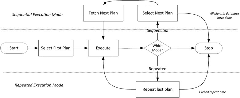
FIGURE 11. State transition diagram of task execution.
The Executor will execute the scripts sent by the scheduler. It maintains state machines to describe the execution state of the task. There are two execution states: IDLE and RUNNING.
The execution of the task is implemented based on the coroutine of the ascynio library. When the executor receives a script, it will check the grammar and delete unsafe operations by checking the abstract syntax tree of the script and create a coroutine to execute the script. Since the coroutine will not block the executor thread, the executor can still receive other commands, such as stop commands.
3.2 Log management and visualization
The log system of RACS2 can be divided into three parts: log collection, log storage and log visualization. The framework of the log system is shown in Figure 12.
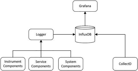
FIGURE 12. Framework of the log system.
The RACS2 provides the Logger component to capture the state switch of components, log requests from other components and the hardware and system running information. The logger organizes this information and saves it into InfluxDB (Naqvi et al., 2017). Different from general relation databases, the InfluxDB, as a Time Series Database (TSDB), contains a timestamp as the primary key of all tables. Therefore, it is an ideal storage backend for logs, and it helps to analyze, display, and diagnose the data.
The log visualization is implemented based on Grafana. Grafana can obtain data from the database and visualize it on the dashboard in real time. The RACS2 also uses Grafana to send user notifications when a variable exceeds the alarm threshold.
3.3 Fault diagnosis and alarm component
Two fault diagnosis mechanisms are provided in the RACS2 framework: fault monitoring within a single component and the alarm component, which monitors the software and hardware exceptions.
The internal failure monitoring mechanism within a single component comes from the design of the component. Each RACS2 component has an error state in addition to its normal state. Error states include three states: NOERROR, NOTREADY, and OUTOFRANGE. In addition, each component can define a unique variety of error states. For each subdivision state of the component, each integer type and floating point classType Property contains two attributes: min_limit and max_limit, which describes both thresholds of a property. Once a variable exceeds its range, an OUTOFRANGE event is triggered, and the error information is written to the log.
The alarm component works as a service. The alarm component will acquire information from other components and determine if there are some exceptions. The rules for finding exceptions are defined by users, and the alarm component uses a Python-based expert system to process these rules. If an unrecoverable failure occurs, the alarm component stops telescope observation and automatically sends notifications to users. Common recoverable failures are usually due to a mistaken command or weather factors, the alarm component will stop the observation at these times and perform a user-defined recovery process.
3.4 Graphical user interface (GUI)
The graphical user interface (GUI) of RACS2 is implemented with a B/S architecture. The RACS2 chose to use the web-based GUI for two reasons. The first reason is that the web-based UI can be accessed from any device (such as a cellphones or laptops), so users do not have to deploy the UI by themselves. The second reason is that the Web-Base UI makes remote control simpler, the backend (Server) needs to be deployed alongside the instruments, while the frontend (GUI) can be accessed remotely, so the control can be done far away from the observatory.
For the RACS2, the backend is an http server based on FastAPI. The server APIs follow the RESTful (Rodriguez, 2008) discipline. The frontend is based on the Vue framework. The GUI consists of four subpages and integrates the functions of device monitoring, device control, observation tasks management and user management. Figure 13 shows the task management page of the system. Users can edit the observation scripts, store the scripts into the database, and trigger an observation task manually with the frontend.
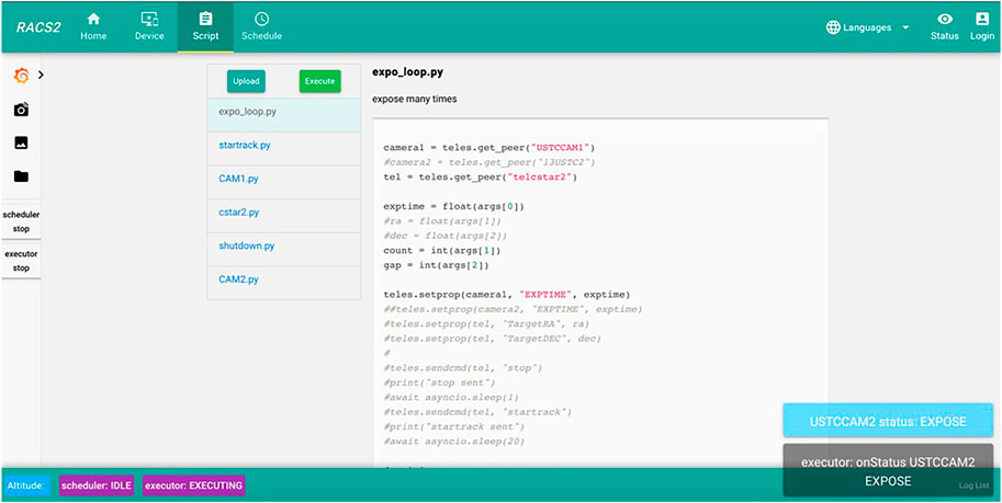
FIGURE 13. Script management page.
For security reasons, the backend has a permission hierarchy system. Only authenticated users are allowed to access the GUI. Important operations, such as editing the observation scripts and reading the database, also need authentication. New users can be added via the user management page.
The web interface covers the requirements of observation and telescope diagnosis. Users can complete the observation task by using the web interface remotely.
4 Test and its performance
4.1 RACS2 functional test
Tests and benchmarking are critical for program quality. Unit tests are used to test each function in a program. The RACS2 project integrates the Google Test framework (Sen, 2010) to implement the unit test for functions and classes. The Python API and all Python-based components are tested with the pytest framework. We also conduct a performance test to measure the performance of the RACS2 component network.
The entire project is managed with TeamCity, a Continuous Integrated (CI) platform. When new code is submitted, the server automatically compiles, publishes, and tests the project and generates corresponding reports and software packages.
4.2 Performance benchmark
To measure the performance of the RACS2 framework, we measured the relationship between messaging latency and concurrency/message size of RACS2 under local area network (LAN) and link local (LO) environments. Two kinds of components, the server and the client, are started to perform the test. The client component sends messages of exponential series size to the server to measure the latency.
Multiple client components are started to simulate a real-word concurrency situation. This method is shown in the following figure. As shown in Figure 14, t1∼tn is the latency from each client, and we use the average latency as the result.
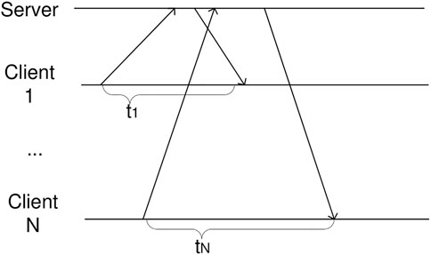
FIGURE 14. Sequence of test messages.
For the LAN group, the server components and client component are started on two different computers (both MTJDb3JlQDIuNkdIeg==) under the same LAN (1,000 Mbps, Ethernet), and for the LO group, the server and the client components are started on the same physical server (MTJDb3JlQDIuNkdIeg==).
The result is shown in Figure 15. The message size of 64 bytes, 1,024 bytes and 8,192 bytes are plotted in the figure. As shown in the figure, the communication is affected significantly by the concurrency. Latency of all setups are under 2000 us. Since most of the messages used in actual projects are sized under 256 bytes, the typical communication delay is less than 1 ms in most circumstances. It is worth mentioning that the LAN group outperforms LO group when concurrency is more than 10, the reason is that for LO groups, when concurrency is more than the number of processor cores, the performance of server component is limited by processor resources. For LAN group, since the server component is running at another machine, such limit is not observed.
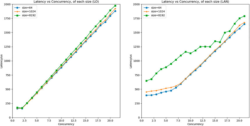
FIGURE 15. Communication latency of RACS2, under link local and local area network.
For comparison, we benchmarked the RTS2 framework in a similar way. The RTS2 has a limitation of 8k bytes for the size of the message, so the result is not one-to-one correspondent to the RACS2’s. Since the RTS2 framework uses the raw socket, it out-performs the RACS2 for short messages (size < 1k), but the RACS2 shows advantages for long messages. We also found that the latency of RTS2 spread more widely, which means that the RACS2 has better determinacy than the RTS2.
5 Applications
At present, the RACS2 has been applied to telescopes for the space debris observation, the observational devices in Antarctica and the control system of the Wide Field Survey Telescope Camera (WFCam) (Chen et al., 2022).
5.1 Space object observation
With an increasing number of rockets, satellites and other spacecraft entering the orbital environment, space debris is also increasing rapidly. Therefore, a number of small and medium-sized optical telescopes are planned around the world to build a space debris monitoring and warning platform.
One of these telescopes is currently under construction. It has a reflecting telescope with a diameter of 60 cm and a focal ratio of F/2.2. The system has a GPS module to provide time service, a serial port-based electronic focuser in the optical tube, an equatorial mount, an electronic dome controlled by a serial port, a webcam, a weather station with a web interface, and a panoramic camera.
It is also equipped with a PX4040 camera with a CMOS sensor size of 9 µm and resolution of 4 K × 4 K@12 bit sampling, which was developed by our laboratory. The frame rate can reach up to 10 fps through the USB3 interface.
We used the RACS2 framework to develop the control and monitor software for this observation. Every piece of equipment, including the telescope mount, dome, camera, weather station, webcam and other devices, is connected to the RACS2 framework. Each subsystem can be accessed via the RACS2 User Interface.
The observation task of space debris is different from those of stellar. For the stellar observation, we send a target position to the mount, enable the tracking procedure, and start taking the picture. However, for space debris, we need to track the space debris by sending a set of positions to the mount and adjusting the movement speed of each axis of the mount. RACS2 provides enough flexibility to accomplish such observation tasks. Because the observation tasks are just some hot pluggable scripts for RACS2, we also implement stellar tracking, flat-field observation and other observation tasks. All these tasks can be called by users when needed.
This system has been running for more than 1 year and has gathered a large amount of data.
5.2 Dome a twins
The Dome A Twins (DATs) telescope system is the second generation of the Antarctic small telescope array after the Chinese Small Telescope aRray (CSTAR). It includes two telescopes, each with a diameter of 145 mm. Each telescope is equipped with a frame-transfer scientific CCD camera E4720 with a resolution of 1K * 1K. Since the whole telescope system will be installed at dome A, Antarctica observatory, all instruments are specially designed for temperatures as low as −80°C.
We built the control system of DATs based on RACS2. The DATs needs to conduct long-term unattended observations in the harsh environment of Antarctica. The DATs has an equatorial mount, two CCD cameras and a power control subsystem. We have already developed the basic control software of these equipment based on the EPICS, so these EPICS IOCs are connected to RACS2 with the EPICS bridge.
The RACS2 system for DATs shares some features of space debris telescopes. All observation tasks of the DATs are stored in the observation database before deploying to the Antarctic, and then the observation tasks will be performed in the Antarctic for several months. Since it is very difficult to access the web interface due to the harsh network environment in the Antarctic, the operation toward RACS2 can be performed with a command-line client via SSH sessions. Regardless, the system management and fault handling mechanism of the RACS2 can ensure that the system survives from most simple exceptions.
At present, the DATs telescope with the RACS2 system has been tested for several months at the Xuyi Station of the Purple Mountain Observatory. It will be deployed to Dome A for scientific observation soon.
6 Conclusion
The Remote Autonomous Control System 2nd is a modern distributed remote autonomous telescope control framework. Due to the decentralized distributed design, lightweight system structure, complete application scheme and excellent performance, the RACS2 is lightweight and easy to use. With the help of the modular design, components are decoupled, new features and support for new devices can be added to the RACS2 by developing new components. By introducing the new communication mechanism, the latency is low and the framework is lightweight. Because of these features, small teams can implement their telescope control systems with RACS2 quite easily, and the RACS2 can be a reference for other frameworks. At present, the RACS2 has been successfully applied to telescopes for space debris observation, the Antarctic telescopes and control systems of wide-field survey telescope camera (WFCam). Still, since the RACS2 is a newly designed framework, it lacks of support for instruments in some ways. Some new features can be added to RACS2 in the future, such as the mechanism for the integration of multiple observatories, automatic observation based on artificial intelligence, and components for some specific astronomical applications, such as time-domain astronomy and radio astronomy. The RACS2 can be adopted by other projects to further construct the ecosystem of the RACS2.
Data availability statement
The original contributions presented in the study are included in the article/supplementary material, further inquiries can be directed to the corresponding author.
Author contributions
Z-YW: writing, system design and implementation. G-YZ: conceptualization, protocol design. M-HJ: system benchmark, implementation. JW: conceptualization, supervision.
All authors listed have made a substantial, direct, and intellectual contribution to the work and approved it for publication. All authors contributed to the article and approved the submitted version.
Funding
This work was supported in part by the Fundamental Research Funds for the Central Universities (WK2360000003, WK2030040064, YD2030000601, and YD2030000602), in part by the National Natural Science Funds of China (Grant Nos 11603023 and 11773026), in part by the Strategic Priority Research Program of CAS (Grant Nos XDC07020200 and XDA15020605), and in part by Frontier Scientific Research Program of Deep Space Exploration Laboratory (Grant No. 2022-QYKYJH-HXYF-012).
Conflict of interest
The authors declare that the research was conducted in the absence of any commercial or financial relationships that could be construed as a potential conflict of interest.
Publisher’s note
All claims expressed in this article are solely those of the authors and do not necessarily represent those of their affiliated organizations, or those of the publisher, the editors and the reviewers. Any product that may be evaluated in this article, or claim that may be made by its manufacturer, is not guaranteed or endorsed by the publisher.
References
Agha, G. (1986). Actors: A model of concurrent computation in distributed systems. Cambridge, MA: MIT press.
Caproni, A., Colomer, P., Jeram, B., Sommer, H., Chiozzi, G., Mañas, M. M., et al. (2016). “ACS from development to operations,” in SPIE Astronomical Telescopes + Instrumentation, Edinburgh, UK, 26 June - 1 July 2016.
Castro-Tirado, A. J. (2010). Robotic autonomous observatories: A historical perspective. Adv. Astronomy 2010, 1–8. doi:10.1155/2010/570489
Chen, C., Zhang, J., Zhang, H. F., Wang, J., Tang, Q. J., Wang, H., et al. (2022). Design of CCD test platform of scientific imaging for wide field survey telescope. J. Astronomical Telesc. Instrum. Syst. 8 (1), 016005. doi:10.1117/1.jatis.8.1.016005
Chiozzi, G., Gustafsson, B., Jeram, B., Plesko, M., Sekoranja, M., Tkacik, G., et al. (2002). “Corba-based common software for the alma project,” in Advanced Telescope and Instrumentation Control Software II, Waikoloa, HI, 22-28 August 2002 (Spie), 43–54.
Dunn, J., Boyer, C., Daly, P. N., Gillies, K., Marshall, R., Silva, D., et al. (2006). “Observatory software for the thirty-meter telescope (TMT),” in SPIE Astronomical Telescopes + Instrumentation,, Orlando,FL, 24-31 May 2006.
Gillies, K., Weiss, J., Subramaniam, A., and Ahmed, M. (2020). “TMT common software final construction update,” in SPIE Astronomical Telescopes + Instrumentation, California, 14-18 December 2020.
Google Protocol Buffers (Protobuf) (2015). Google’s Data Interchange Format. Documentation and open source release. Available at: https://developers.google.com/protocol-buffers (Accessed December 08, 2015).
Götz, A., Taurel, E., Pons, J. L., Verdier, P., Chaize, J. M., Meyer, J., et al. (2003). TANGO a CORBA based Control System. ICALEPCS2003, Gyeongju.
Grosbøl, P. (1991). The FITS data format. Databases On-Line Data Astronomy 171, 253–257. doi:10.1007/978-94-011-3250-3_25
Johnson, J. M., Mader, J. A., and Tsubota, K. (2013). “Keck telescope control system upgrade project status,” in Proceedings of the 14th International Conference on Accelerator & Large Experimental Physics Control Systems, San Francisco, CA, 6-11 October 2013.
Kubánek, P., Jelínek, M., Vítek, S., Postigo, A. D. U., Nekola, M., French, J., et al. (2006). “RTS2: A powerful robotic observatory manager,” in SPIE Astronomical Telescopes + Instrumentation, Orlando, FL, 24-31 May 2006.
Kubánek, P., Jelínek, M., French, J., Prouza, M., Vítek, S., Tirado, A. J. C., et al. (2008). “The RTS2 protocol,” in SPIE Astronomical Telescopes + Instrumentation, Marseille, 23-28 June 2008, 92.
Liu, J., Soria, R., Wu, X. F., Wu, H., and Shang, Z. (2021). The sitian project. An. Acad. Bras. Ciências. 93 (1), e20200628. doi:10.1590/0001-3765202120200628
Lupton, W., Lewis, H., and Honey, A. (1994). W.M. Keck Telescope control system. Bellingham, WA: International Society for Optics and Photonics.
Macedo, T., and Oliveira, F. (2011). Redis cookbook: Practical techniques for fast data manipulation. Sebastopol, CA: Reilly Media, Inc.
Marathe, N. (2015). An Introduction to libuv. Available at: https://nikhilm.github.io/uvbook/.
Marathe, N. (2021). An Introduction to libuv[EB/OL]. Available at: https://nikhilm.github.io/uvbook/An%20Introduction%20to%20libuv.pdf (Accessed March 09, 2021).
Mills, D., Schumacher, G., and Lotz, P. (2016). “Lsst communications middleware implementation,” in Ground-based and Airborne Telescopes VI, Edinburgh, UK, 26 June - 1 July 2016 (Spie), 1860–1869.
Naqvi, S. N. Z., Yfantidou, S., and Zimányi, E. (2017). Time series databases and InfluxDB. Brussels: Studienarbeit, Université Libre de Bruxelles.
Pezoa, F., Reutter, J. L., Suarez, F., Ugarte, M., and Vrgoč, D. (2017). “Foundations of JSON schema,” in Proceedings of the 25th International Conference on World Wide Web, Montréal, April 11 - 15, 2016, 263–273.
Roestenburg, R., Williams, R., and Bakker, R. (2016). Akka in action. New York, NY: Simon & Schuster.
Schumacher, G., Warner, M., and Krabbendam, V. (2006). “LSST control system,” in SPIE Astronomical Telescopes Instrumentation, Orlando, FL, 24-31 May 2006, 627403.
Sefraoui, O., Aissaoui, M., and Eleuldj, M. (2012). OpenStack: Toward an open-source solution for cloud computing. Int. J. Comput. Appl. 55 (3), 38–42. doi:10.5120/8738-2991
Wang, J., Jin, G., Xiao-qi, Y. U., Huang, K., Feng, L. I., and Ren, J. (2006). The design of observatory control system of LAMOST. Plasma Sci. Technol. 8 (3), 347–351. doi:10.1088/1009-0630/8/3/22
Wang, J., Liu, J. J., Tang, P. Y., Min-cheng, L., Wu, W. Q., Zhang, G. Y., et al. (2013a). A study on generic models of control systems of large astronomical telescopes. Publ. Astronomical Soc. Pac. 125 (932), 1265–1276. doi:10.1086/673492
Wang, J., Luo, M. C., Wen-qing, W. W., Liu, L. J., Tang, P.-Y., Zhu, L. C., et al. (2013b). Study of central control system for FAST. Exp. Astron. 36 (3), 569–589. doi:10.1007/s10686-013-9345-2
Watson, A. (2002). “OMG (Object Management Group) architecture and CORBA (common object request broker architecture) specification,” in Distributed Object Management, IEE Colloquium On, London, 14 January 1994.
Williams, S. J., Bridger, A., Chaudhuri, S. R., and Trivedi, V. (2016). “The SKA observation control system,” in Spie Astronomical Telescopes Instrumentation, Edinburgh, UK, 26 June - 1 July 2016.
Zhang, G.-Y., Wang, J., Tang, P.-Y., Jia, M.-H., Chen, J., Dong, S.-C., et al. (2016). An autonomous observation and control system based on EPICS and RTS2 for antarctic telescopes. Mon. Notices R. Astronomical Soc. MNRAS 455 (2), 1654–1664. doi:10.1093/mnras/stv2299
Keywords: autonomous observations, remote control, experimental physics and industrial control system (EPICS), ZeroMQ (ZMQ), RACS2
Citation: Wang Z-Y, Zhang G-Y, Wang J, Geng Z, Zhu Z-Y, Jia M-H, Zhang Q, Zheng Z-H, Ge K, Gu J-Y, Zhu L-C and Zhang H-F (2023) RACS2: a framework of a remote autonomous control system for telescope observation and its application. Front. Astron. Space Sci. 10:1104150. doi: 10.3389/fspas.2023.1104150
Received: 21 November 2022; Accepted: 28 April 2023;
Published: 11 May 2023.
Edited by:
Simon Pete Worden, Other, United StatesReviewed by:
Peter Klupar, Breakthrough, United StatesPhilip Mauskopf, Arizona State University, United States
Copyright © 2023 Wang, Zhang, Wang, Geng, Zhu, Jia, Zhang, Zheng, Ge, Gu, Zhu and Zhang. This is an open-access article distributed under the terms of the Creative Commons Attribution License (CC BY). The use, distribution or reproduction in other forums is permitted, provided the original author(s) and the copyright owner(s) are credited and that the original publication in this journal is cited, in accordance with accepted academic practice. No use, distribution or reproduction is permitted which does not comply with these terms.
*Correspondence: Jian Wang, d2FuZ2ppYW5AdXN0Yy5lZHUuY24=