
94% of researchers rate our articles as excellent or good
Learn more about the work of our research integrity team to safeguard the quality of each article we publish.
Find out more
ORIGINAL RESEARCH article
Front. Astron. Space Sci., 30 August 2022
Sec. Nuclear Physics
Volume 9 - 2022 | https://doi.org/10.3389/fspas.2022.949920
This article is part of the Research TopicNuclear Physics and Astrophysics in Plasma TrapsView all 11 articles
In the recent past, the possibility to use a superconducting trap confining a hot and dense plasma as a tool to investigate radioactivity in astrophysical scenarios has been proposed. Making possible these kind of unprecedented measurements is the main aim of the PANDORA (Plasmas for Astrophysics Nuclear Decays Observation and Radiation for Archaeometry) project. In this context, it is planned to build a compact and flexible magnetic plasma trap where plasma reaches an electron density ne ∼ 1011–1013 cm−3, and an electron temperature, in units of kT, kTe ∼ 0.1–30 keV. The setup is conceived to be able to measure, for the first time, nuclear β-decay rates in stellar-like conditions in terms of ionization states. In this paper, the design study of a mm-wave polarimeter for the PANDORA plasma line-integrated electron density measurement is presented. The paper highlights the method of this type of measurements for the first time proposed for a magneto-plasma trap which represents an “intermediate” case between the ultra-compact plasma ion sources and the large-size thermonuclear fusion devices. Preliminary measurements at scaled microwave frequencies have carried out both on a “free-space” setup by using a wire-grid polarizer and a rotable Ka-band OMT + horn antennas system, and on a compact trap (called Flexible Plasma Trap) installed at INFN-LNS and used as PANDORA down-sized testbench are described. The polarimeter technique will support β-decay investigation by simultaneous measurements of the total plasma density, which is crucial to carefully evaluate the decay-constant and to extrapolate the laboratory observed data to the astrophysical scenarios. Moreover, this work proposes to adopt an electromagnetic inverse-scattering-based technique-based method to retrieve the electron density profile along the probing antennas line-of-sight. Numerical results of this so-called “inverse profilometry” are also shown.
Interferometers and Polarimeters are well-assessed tools, developed for plasma diagnostics in thermonuclear fusion machines (Zhang et al., 2012; Tudisco et al., 2013; Creely et al., 2020) to measure both line-averaged density and magnetic field, also in the so called “InterPol” combined setups. In compact electron cyclotron resonance (ECR) ion sources (ECRIS) this is a challenging task due to the extremely tenuous plasma (if compared to densities of thermonuclear fusion reactor plasmas) and to their compact size. Due to the typical density range of ECR plasmas (1011–1012 cm−3), in fact, the probing beam wavelength λp ∼ cm is comparable to the plasma (LP) and chamber (LC) size: λp ∼LP ∼ LC. Moreover, in ECRIS the measurement is greatly complicated by the mechanical constraints, which limit considerably the ratio L/λp. The main problem consists in the multipaths given by probing signal reflections at the chamber walls (acting as reflecting surfaces). Starting from 2014, new tools and analysis techniques have been developed by INFN-LNS ion source group allowing the direct measurement of the absolute plasma density by using an interfero-polarimetric system. In particular:
• the interferometric measurement is based on a “frequency swept method”, which moves from the one described in (Scime et al., 2001; Howard et al., 2018), and it has been specifically developed for the special ECRIS-like scenario (Torrisi et al., 2017; Mascali et al., 2022a).
• Also for the polarimetric technique in compact traps, such as ECRIS, a specific original approach has been proposed and implemented to discriminate the polarization plane rotation due to magnetoplasma Faraday rotation only, excluding the spurious effects induced by the cavity resonator thanks to a measurement protocol able to select whether or not polarization was following the Malus law. It was therefore possible to extrapolate the value of the electron density as a free-parameter of a best fit procedure, in good agreement with the value obtained by the interferometer technique. The complete analysis can be found in (Naselli et al., 2018).
While the above-mentioned measurements refer to compact plasma chamber testbench at INFN-LNS (Naselli et al., 2019) and on the ion source of ATOMKI laboratory, in Debrecen (Hungary) (Biri et al., 2018) having typical size of about 30 cm in length and 10 cm in diameter, the case at hand concerns a large plasma trap—referring to the PANDORA project (Mascali et al., 2022b) — which is 70 cm in length and 28 cm in diameter and it can be considered as a “bridge” case between compact traps and large size fusion plasma device also in terms of electron density ne range (∼ 1011–1013 cm−3). It should be mentioned that heterodyne interferometer for measuring the plasma electron density in the same range of the PANDORA case—for example in Helicon linear plasma devices - has been developed and characterized in the laboratory (Wiebold and Scharer, 2009; Li et al., 2021).
Anyway, from one hand, at least at the beginning of the PANDORA experimental test, the same method of the ECRIS (which are the only approaches which allowed up to now measuring the plasma density in very compact traps) will be applied as a cross-check and confirmation of the validity of the assumptions and numerical results. On the other hand, the new approach could allow to improve significantly the information, also reducing the measurement time; for the purposes of PANDORA it is in fact very important performing “live” measurement of the total plasma density. Beside supporting R&D in plasma based ion sources, the importance of diagnostics and multi-diagnostic setups is in fact growing for measuring the magneto-plasma properties in experiments devoted to astrophysics and nuclear astrophysics research in compact plasma traps, such as the PANDORA project (Mascali et al., 2022b) aiming to the study of β-decays of nuclear astrophysical interest for the first time in a ECR magnetoplasma (which represents an enviroment able to reproduce some stellar-like properties). This has motivated the development of techniques and devices probing these plasmas in a non-invasive way and operating in different energy ranges (Biri et al., 2018; Naselli et al., 2019; Mascali et al., 2022a). The PANDORA magnetic system, the overall injection system, including the microwave lines for plasma heating and the isotopes injection schemes with a focus on the developments of the oven for solid elements, has been presented in (Mauro et al., 2022).
The design study of a mm-wave polarimeter presented in this paper highlights the method of this type of measurements for the first time proposed for a magneto-plasma trap. In particular the proposed W-Band polarimeter - using intermediate frequency down-conversion (super-heterodyne) that uses a sub-harmonic mixer before the signal detection - finds strong similarities with experiments in the field of radio astronomy devoted to analyzing the Cosmic Microwave Background (CMB) polarization for the detection of the gravitational waves and other cosmological parameters (Cano et al., 2015; Pascual et al., 2021). In general, the main challenges are due to the limited accesses for the probing horn antennas which need to be tilted to illuminate plasma center, a large range of electron density (varying with the microwave power, magnetic field confinement) and eventual multipaths which have been mitigated by a proper sizing of the setup as shown in the following sections. The paper is organized as follows: In Section 2, the dimensioning and choice of the operating probing frequency/wavelength is described. In Section 3, the following two super-heterodyne schemes are presented and compared:
1. Detection of Lissajous figure: direct RF signals detection which allow the real-time reconstruction of the State of Polarization (SOP) curve described by the electric field vector. This result can be obtained by using the Lissajous picture from a two channels scope in an x-y representation.
2. Stokes Parameters detection based on phase-switches processing.
In Section 4 polarimetric measurements performed in a free-space setup by using a rotating wire-grid polarizer and Ka-band OMT + horn antennas system, and on a compact trap installed at INFN-LNS and used as PANDORA down-sized testbench, are described. In Section 5, the preliminary design of a profilometer is presented. Conclusion are drawn in Section 6.
In the frame of the PANDORA (Plasmas for Astrophysics Nuclear Decays Observation and Radiation for Archaeometry) project (Naselli et al., 2022), a new experimental approach aims at measure, for the first time, in-plasma β-decays lifetimes of isotopes of nuclear astrophysical interest as a function of thermodynamical conditions of the environment, namely a laboratory magnetized plasma able to mimic some stellar-like conditions. The experimental approach consists in a direct correlation of the plasma environment and nuclear activity, and this can be done by simultaneously identifying and discriminating - through an innovative multi-diagnostic system which will work synergically with a γ-rays detection system - the photons emitted by the plasma (from microwave to hard X-ray) and γ-rays emitted after the isotope β-decay. A high-performance electron-cyclotron-resonance plasma trap, with a fully superconducting magnetic system where the radionuclides can be maintained in a dynamical equilibrium for weeks, has been purposely designed. Setup and tools typically at the service of particle accelerators physics and applications have been thus redesigned on purpose, by means of innovative upgrade and improvements, for realizing new experimental system for fundamental and multidisciplinary studies of nuclear physics and astrophysical interest. The overall structure of PANDORA project can be structured on three main pillars:
1) Magnetic Trap: A set of superconducting coils able to confine the plasma. The design will allow access to the plasma core for the diagnostics system and γ-ray detectors (Mauro et al., 2022). The PANDORA magnetic confinement system will be fully superconductive and composed by three superconducting coils for axial confinement and by six superconducting hexapole coils for radial confinement, which are coaxial with respect to the axial coils (see Figure 1). It is the largest magnetic trap ever designed in a B-minimum scheme, supporting a cylindrical plasma chamber of 700 mm length and 150 mm external radius (internal radius of 140 mm). The maximum fields of 2.7 T and 3 T along the chamber axis and 1.5 T along the chamber inner surface will allow stable plasma generation through an RF field at the frequencies of 18 and 21 GHz via ECR. Figure 2A shows the magnetic field intensity |B| plot (values given in [T]) on a rectangular surface corresponding to the plasma chamber dimensions (280 × 700 mm2) on the xy plane.
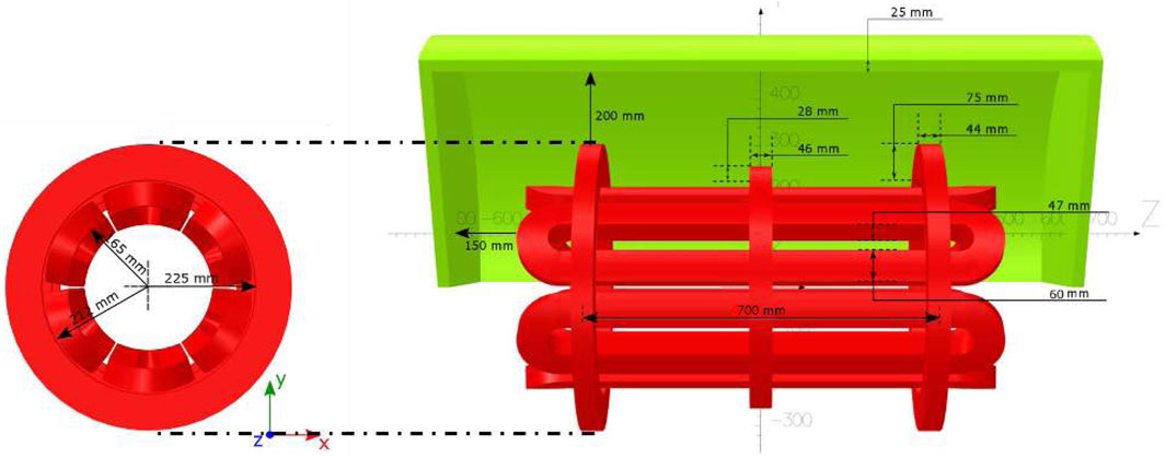
FIGURE 1. View of the magnetic system configuration with its fundamental simulated dimensions. Green element represents the iron yoke (1/3 symmetry).
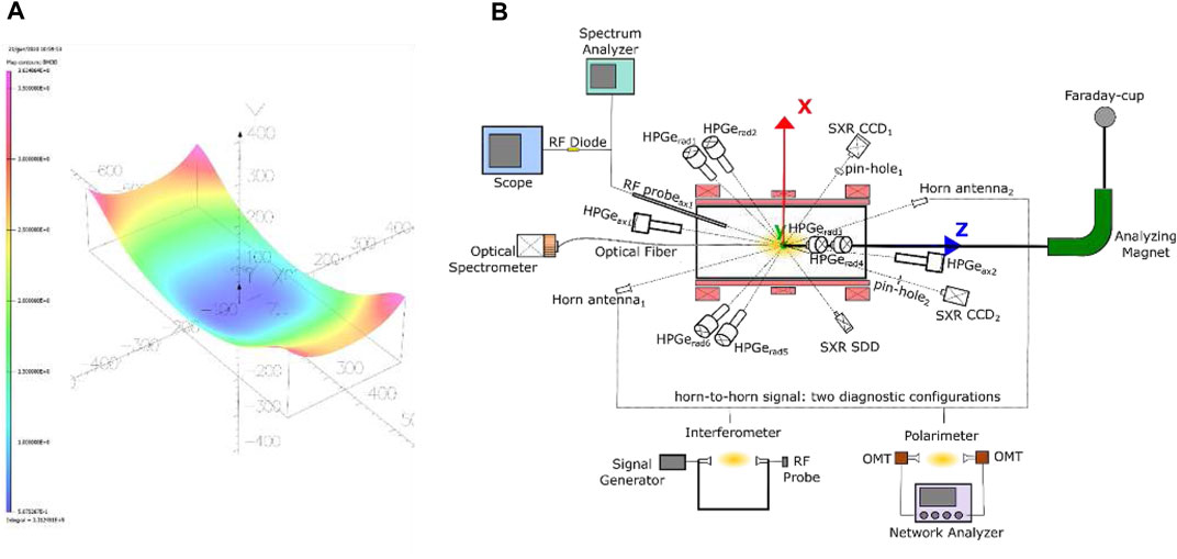
FIGURE 2. (A) 2D (histogram) plot of the magnetic field module |B| inside the plasma chamber, on the xz plane. Values ranges from 1 (violet) to 3.5 (magenta) and are expressed in [T]. (B) Pictorial sketch of the integrated set of PANDORA diagnostics, highlighting the detectors for X-ray spectroscopy and imaging, optical emission spectroscopy and polarimetry.
2) Array of 14 HPGe detectors for γ-ray spectroscopy: The array will be used to tag the in-plasma nuclear decays via the γ-rays emitted from the excited states of the daughter nuclei (Hartfuss and Geist, 2013).
3) Advanced plasma diagnostics system, made of tens of non-invasive diagnostics tools: For the non-intrusive inspection of the plasma environment proprieties and the measurement of plasma parameters to be correlated with the nuclear decays (Naselli et al., 2019).
In more detail, plasma will be characterized in terms of:
• Plasma density and temperature of the cold, warm and hot electron component by using, respectively, a Visible light (VL) camera, Silicon Drift Detector (SDD) and a High-purity Germanium (HPGe) detector;
• Plasma structure, volume, dynamics of losses and confinement by two (axial and radial) advanced X-ray pin-hole cameras for 2D space resolved spectroscopy;
• Line-integrated total electron density measurement by polarimetric system;
• Plasma emitted EM wave in GHz ranges, by means of a two-pins RF probe installed inside the plasma chamber connected to a Spectrum Analyzer (SA), in order to monitor and master plasma stability;
• Moreover, all diagnostics tools can operate simultaneously with the Faraday cup in order to measure the ion charge state distribution (CSD). It has been possible to correlate all the detected plasma parameters with the characteristics of the beam extracted on-line.
A sketch of the integrated set of PANDORA diagnostics and of the γ-ray HPGe array, is shown in fugure 2(B). Among the others diagnostic techniques, the polarimetric system is the only tool able to perform total line-integrated plasma density measurement, and both its dimensioning for the PANDORA scenario and preliminary benchmark measurements will be presented in this paper.
Since the design of the advanced PANDORA plasma trap is ongoing, the benchmark experimental measurements were carried out in a down-sized compact traps used as PANDORA test-bench, the compact Flexible Plasma Trap (FPT), installed at INFN LNS.
The proper choice of the probing frequency f (or wavelength λp) has important consequences from the accuracy and reliability of the diagnostic setup, therefore it must be selected carefully in order to balance several competing effects and aspects such as the maximum plasma density, profile shape, density gradient, plasma accessibility through vacuum ports. While for interferometry the phase shift decrease linearly with increasing the probing frequency, the Faraday effect decreased with the square of the probing frequency: the probing frequency should not be chosen too high in order to avoid marginalization of the quantities of interest. The probing wavelength λp used for plasma probing must fulfill first of all the condition that the corresponding critical density nc = 4π2(c2/λ2)(ϵ0me/e2) = 1.115 × 10¹⁵m2/λ2 m−3 is higher than the central electron density n0 needed to avoid cutoff (Heald et al., 1965) which corresponds also to keep ω ≫ ωp where ω is the probing (angular) frequency and ωp is the plasma frequency. As a first preliminary estimation of the operating probing wavelength, since the expected peak density for PANDORA is about n0 = 4 ⋅ 1012 cm−3, and assuming nc = 2 ⋅ 1013 cm−3, a wavelength λp < 16.7 mm (f > 90 GHz) is demanded, which correspond to ω ∼ 5ωp. In principle further restrictions are imposed from ray refractions through the plasma since the ratio between plasma diameter D and wavelength (D/λp) must be large enough (Galata et al., 2022).
However, the PANDORA plasma chamber is a large cylinder (diameter Dc = 280 mm and length Lc = 700 mm) where it is possible to generate and confine a plasma with an estimated diameter of D = 150 mm with an electron density range from 1011–1013 cm−3 (Gammino et al., 2017). Such a density range (the mean density values that can be achieved) combined with the large plasma size is less challenging with respect to the compact plasma case resulting in a (D/λp) ratio equal to ∼ 9. Moreover, to obtain more precise and detailed information necessary for the design study, the density and magnetic profiles have been estimated. Figure 3A shows the magnetic field (in blue) and the electron density profile (in red) - considering a Gaussian density profile having a maximum value n0 = 4 ⋅ 1018 m−3- along the longitudinal z-axis. This value refers to the maximum density giving a certain density profile (as shown in the Figure 3A) while the corresponding mean density is 2.5 ⋅ 1018 m−3. Density profiles and the Faraday rotation angles estimate are also shown for a case of a lower density (Figure 3C) and a case of higher density (Figure 3D). Lower density values lower are not expected in PANDORA, because it will be needed to operate at high density and temperature domain as much as possible in order to improve the effect of the physical processes (beta-decay lifetime variation in-plasma) that PANDORA aims at measuring.
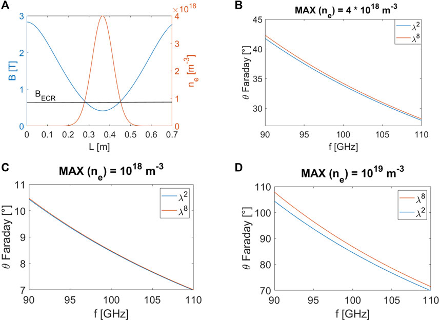
FIGURE 3. (A) Magnetic field (blue) and electron density (red) profiles on the longitudinal z-axis of the PANDORA plasma chamber, considered for the Faraday rotation angle estimation. (B) Faraday rotation angle θFaraday vs. probing frequency f considering a Gaussian density profile having a maximum value n0 = 4 ⋅ 1018 m−3. (C) The same of (B) at a maximum value n0 = 1018 m−3. (D) The same of (B) at a maximum value n0 = 1019 m−3.
The Faraday rotation angle θFaraday has been evaluated for two different approximations of the Faraday law: 1) the so-called “λ-square” law (blue curve in Figure 3B):
That is valid in case ω ≫ ωpand ω ≫ ωg, and 2) the 4th order truncated Faraday law (red curve in Figure 3B) (Naselli et al., 2018)):
vs. the probing frequency f. Figures 3B–D shows that in the mm-wavelength range corresponding to a frequency range of 90–110 GHz, the Faraday angle is large enough to be detected and constrained to avoid ambiguity of ± nπ. Therefore, as an optimal compromise between sensitivity, bandwidth (and costs) required by the components which will form the InterPol setup, the operating frequency range has been fixed between 90 and 100 GHz.
An envisaged mechanical scheme of the two antennas mounted respectively in the injection and extraction flange of the PANDORA plasma chamber is shown in Figure 4. The position/orientation of the two antennas has been chosen in order to direct the probing wave through the plasma center and avoid any mechanical interferences with the other components (pumping microwave injection line, oven, bias disk, other diagnostics access (Hartfuss and Geist, 2013)). The maximum allowed antenna aperture diameter is 30 mm which allow to obtain good performances (|S11|, directivity) in the operating mm-wave frequency range of 90–100 GHz and at same time, to avoid mechanical interference with other components. Special dielectric lens will be used with the double function to focus and provide the vacuum tightness and separation between the UHV (Ultra High Vacuum) inside the plasma chamber and the atmospheric pressure outside.
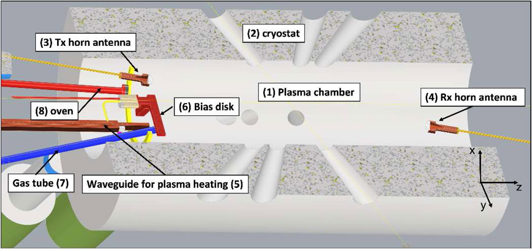
FIGURE 4. Cross-sectional view of the PANDORA plasma chamber (1) which will be installed inside the visible bore of the cryostat (2): the two horn antennas (3) and (4) are placed co-aligned and directed towards the plasmoid center. Plasma is heated through 5 kW microwave coming from rectangular waveguides, one is shown (5). Morever in the view it is shown: the bias disk (6) electrode negatively biased with respect to the source potential for ion beam current increase; the gas injection tube (7) for gaseous element production; the oven (8) for producing ions of metallic elements.
The mm-waves radiated by the polarimeter horn antenna in the PANDORA plasma chamber has been simulated by using the “Wave Optics”® module of the COMSOL Multiphysic®package. It exploits the “Beam Envelope” approximation - based on the assumption that the electric field can be factored into a slowly varying amplitude factor and a prescribed rapidly varying phase factor - for solving problem which extends over domains that are a large number of wavelengths long, without requiring the use of large amounts of memory. The PANDORA plasma chamber domain is in fact much larger than the polarimeter operating wavelengths (L ∼ 200λp, R ∼ 80λp @90 GHz). In order to check the wave behaviour a 2D rectangular geometry (L × R) has been employed in place of the 3D cylinder. The source antenna has been modeled as an incident Gaussian beam electric field of beam radius w0 = 20 mm and distance to focal plane p0 equal to 0 mm. Moreover, a direction of wave propagation k has been imposed by setting θ = 22° in the following conditions kx = k0 cos θ and ky = k0 sin θ in order to resemble the mechanical tilt angle on the antennas to be in reciprocal visibility and let the wave passing through the plasma center. Finally two cases have been simulated:
1) All “Perfect Electric Conductor” (PEC) boundary conditions (see Figure 5A)
2) In correspondence of the receiving horn antenna a “Scattering” boundary makes the boundary transparent for the incoming wave (see Figure 5B)
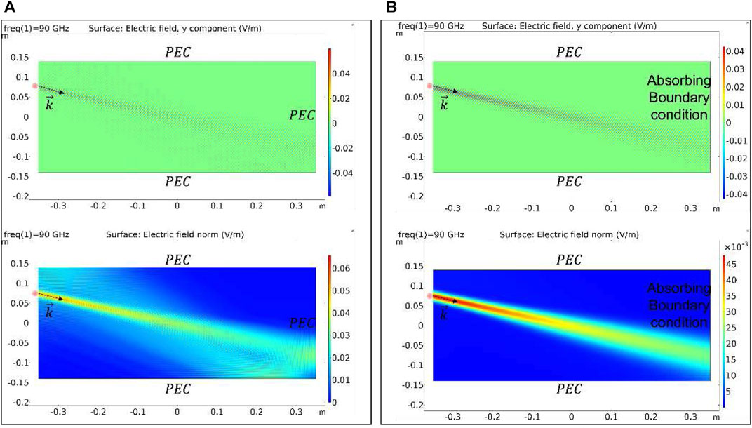
FIGURE 5. Simulated Electric field y component (top) and intensity (bottom) for the all ”Perfect Electric Conductor” case (A) and in presence of the receiving horn antenna modeled as ”Scattering” absorbing boundary (B).
These two boundary conditions represent the worst case where the receiving antenna is modelled as a reflector since all the surfaces surrounding the antenna are PEC resulting in an increase of multireflection and the best scenario where the receiving antenna is approximately modeled as a prefect absorber with an Absorbing Bundary Condition (ABC). In both cases it can be seen that the chosen position for the two antennas allows a line-of-sight propagation; this direct path from the Tx to Rx antenna: 1) illuminates the plasma center; 2) minimizes interference/multipaths. The adding of a dielectric lens will allow decreasing the mechanical size of horns (considering the reduced space that we have on the injection flange) by keeping a reasonable high gain (up to ∼ 20 dB). This lens shall have a permittivity value chosen as a compromise between beam shaping and the undesired internal reflections. However, also considering the vacuum-tightness role of the lens and the high temperature plasma, possible material will be alumina or quartz.
The polarimeter system employs a 90–100 GHz Gunn diode oscillator which generates ∼20 dBm of microwave power. Gunn output power is coupled to the transmitting horn antenna. As stated in the Introduction, two super-heterodyne schemes are proposed. Both schemes consist of two W-band horn antennas, where the main characteristic should be a very low cross-polarization value (better than − 30 dB). The receiving one is connected to an orthomode transducer (OMT), two low-noise amplifiers (LNA) and two filter. The two output signals components of the wave received by the antenna are delivered to two subharmonic mixers which convert the mm-wave to intermediate frequency with conversion losses of around 15 dB and a wide IF bandwidth from 0.1 to 15 GHz. These signals are amplified and filtered. The bandpass waveguide filter in front of the mixer defines the system bandwidth, from 90 to 100 GHz, and rejects the image band. The use a sub-harmonic mixer minimizes the W-band hardware thus making the hardware design easier and enables the usage of a 20 GHz 80 GS/s (40 Gs/s if operating with two channels simultaneously) scope to measure the Lissajous’s figure. An adjustable phase shifter is inserted for initial calibration in absence of plasma.
The last part of the receiver block diagram depends on what scheme we are considering. The scheme based on the Detection of Lissajous figure (see Figure 6A) consists of direct RF signals detection through a scope. This allows the real-time reconstruction of the State of Polarization (SOP) curve described by the electric field vector. This result can be obtained by using the two channels scope in an x-y representation.
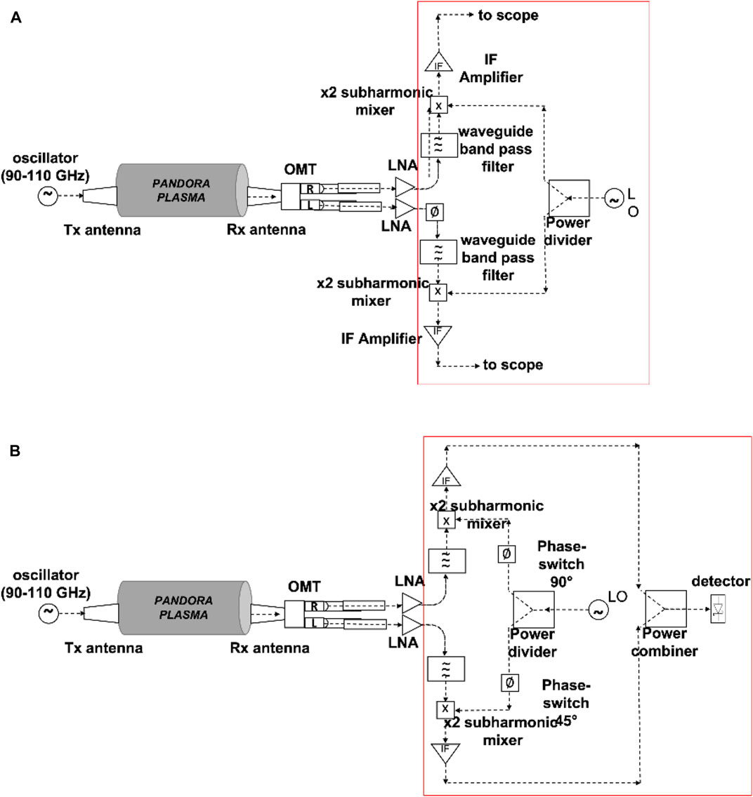
FIGURE 6. (A) Lissajous scheme: simplified block-diagram of the mm-wave polarimeter for PANDORA. (B) Stokes Parameters detection scheme: simplified block-diagram of the mm-wave polarimeter for PANDORA.
On the other hand, Figure 6B shows the scheme for the Stokes Parameters detection based on phase-switches processing. The OMT separates the left-hand and right-hand components of the incoming signal, providing the required signals for the Stokes parameters calculation. The IF signals, amplified using commercial amplifiers, are combined in order to allow the detection with a Schottky diode detector. In this case the polarimeter measures the Stokes parameters (I, Q and U) in order to characterize the polarization. Each element of the Stokes vector represents a measurable intensity which can be detected by a power meter without the need of expensive high-frequency high sample rate scope. These parameters are obtained after combining measurable output signals in the receiver based on electronic phase switching which provides different combinations. Since there are two different phase switches, the polarimeter will have four possible states. Therefore, the Stokes parameters required to measure the input signal polarization can be obtained following by covering all the states of the phase switches cycle. That is, the proposed scheme needs four times more time to collect the information.
n order to validate other possible methodologies of polarization angle measurements, we opted for making a series of measurements at scaled microwave frequencies have carried out on a free-space test-bench by using a rotating wire-grid polarizer and Ka-band OMT + horn antenna system (see the scheme in Figure 7). The measurement consists in the Lissajous figures detection - through the “X-Y” scope representation of the signals coming from the two orthogonal OMT ports - at different angle positions of the rotating wire grid polarizer (see the pictures of the experimental setup in Figure 8).
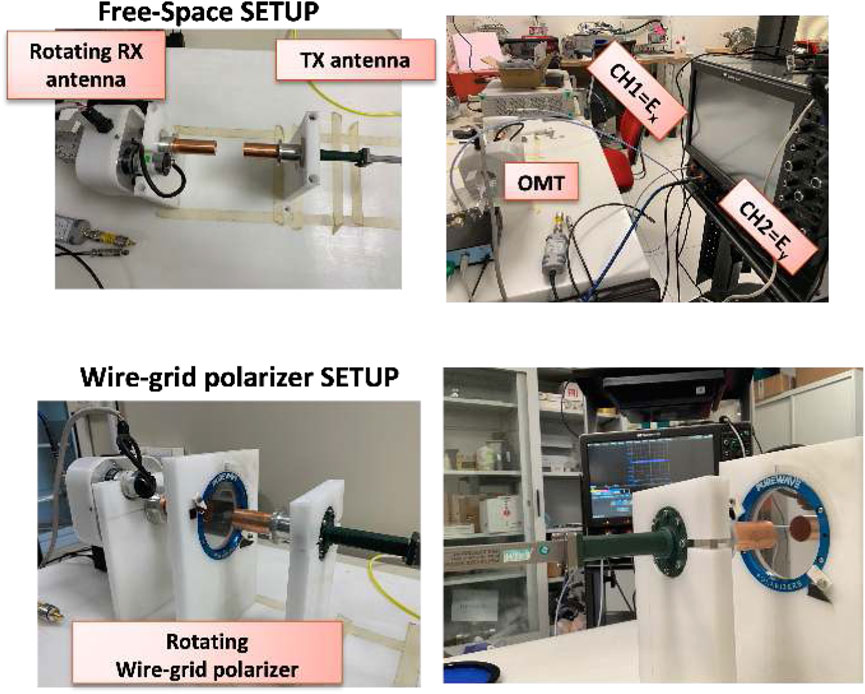
FIGURE 8. Photographs of the Free-space testbench showing the two Ka-band conical horn antennas, the OMT, the wire-grid polarizer and the 20 GHz 80 GS/s (40 Gs/s in this case since the detection is performed on the two channels, simultaneously) scope.
The objective of the measure is to find the angle between the x- axis and the major semiaxis which is imposed by the orientation of the wiregrid polarizer with respect to the linearly polarized (horizonal axis) electric field emitted by the Tx antenna.
This imposed wiregrid angle resembles the “Faraday” rotation angle induced by the plasma. The distance between the two horns has been fixed equal to 40 mm to ensure a good received signal level. The frequency has been fixed equal to 18 GHz, which the lowest operating frequency for the antennas, in order to improve the scope reconstruction at 40 GS/s (two channels). Even for this “low” operating frequency the scope was under sampling since the maximum oscilloscope sample rate is not sufficient for a accurate reconstruction of the 18 GHz signal. As a consequence - although the initial phase difference due to cables different length/delays was compensated by using the “deskew” function of the scope - this under sampling produces a reconstruction error; in particular, while the expected polarization pattern was a line segment, the detected shape of the Lissajous figures was an ellipse due to an artifact relative frequency/phase difference induced by the above-described under-sampling. However, despite these “hardware”-limitations, the obtained angles between the horizontal and major semi-axis are in very good agreement with the expected ones as it can be seen in Figure 9 and Table 1. The Lissajous’s figures have been obtained at different position of the wire grid (the error of the polarizer angle setting is ± 2°, while the error of the estimated angle by Lissajous figure is ± 0.1°). The measured angles are perfectly compatible with the set ones within the error bars. This excellent agreement validates the Detection of Lissajous figure-based scheme; on the other hand it is needed a mixer to downshift the frequency at value inside the analog bandwidth and the sampling rate capability of the scope. In perspectives, the setup will be properly improved by adding two mixers (one for each output signal read by scope) for the future PANDORA measurements. In the case of “in-plasma” measurements, in which the density will be determined from the Faraday angle by means of a fit procedure, the uncertainty will increase and will be estimated by propagating the errors starting from the uncertainties obtained in the fit parameters. In the previous measurements performed on ECRIS (Naselli et al., 2018) we obtained uncertainties of the order of 30%, but in PANDORA we expect to be able to reduce the corresponding uncertainties due to the larger size of the chamber and the consequent lower presence of spurious events than ECRIS case, that were, in fact, the main source of noise affecting the signal-over-background ratio.
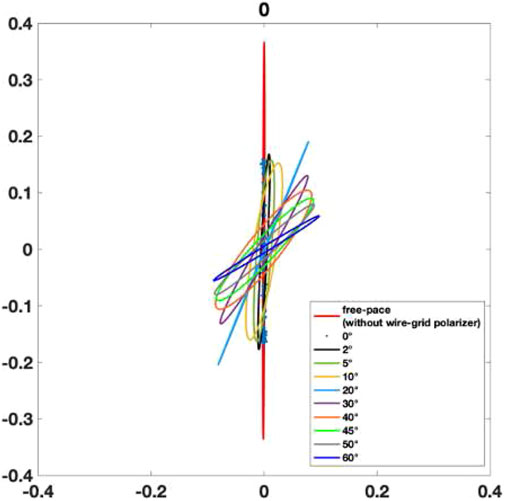
FIGURE 9. Experimental Lissajous figures produced from an elliptical fit of the Lissajous pattern X-Y scope detection at different angular position of the wire-grid polarizer.
The option of making full and direct reconstruction of Lissajous patterns was attempted also considering a real plasma test-bench. Hence, further preliminary polarimetric measurements have been carried out by connecting the two horn antennas to the cylindrical vacuum chamber of the Flexible-Plasma-Trap (FPT) (Di Donato et al., 2019a), which is a compact plasma trap installed at INFN-LNS and used as down-sized test-bench of PANDORA.
In Figure 10, a photograph pf the plasma-testbench is shown. The plasma is heated thanks to a 500 W maximum RF TWT amplifier with a working frequency range 4–6 GHz. The simple-mirror confinement magnetic field profile along the longitudinal axis of the plasma chamber is shown in Figure 11.
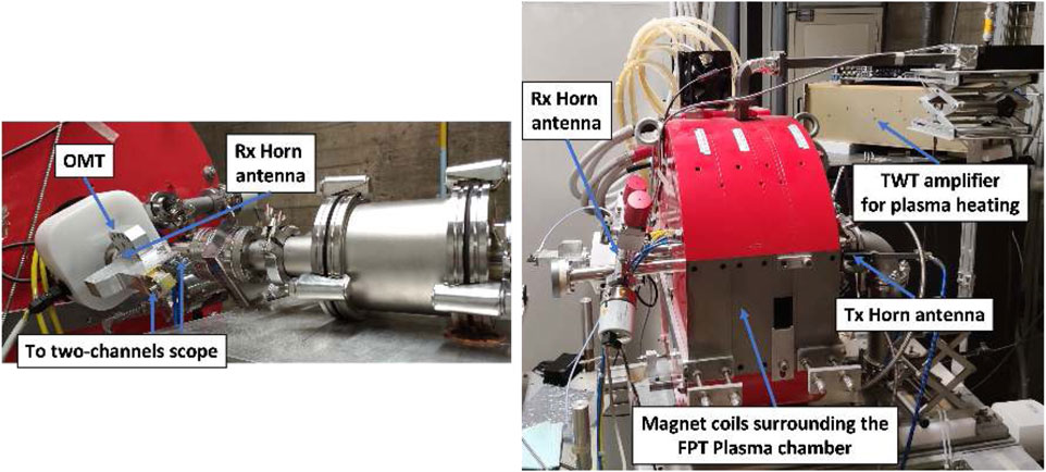
FIGURE 10. Pictures of the Flexible Plasma Trap (FPT) testbench showing the two Ka-band conical horn antennas and the two ports of the OMT connected to the 20 GHz 80 GS/s (40 Gs/s in this case since the detection is performed on the two channels, simultaneously) scope.
Of course, also in this case, mixers are needed for an accurate reconstruction of the 18 GHz signal operating with a sampling rate of (40 GS/s). Anyway, preliminary and qualitative measurements were done in order to verify the sensitivity of the polarimetric system in detecting the plasma, i.e., using the tool only as “signature” of plasma ignition and not for quantitative estimations.
The measurements vs. the RF pumping power (from 0 to 70 W) have been performed and are shown in Figure 12. It can be seen that the polarization ellipse detected after the plasma ignition (at 10 W) is well distinguishable from that of the switched off plasma. Furthermore, it is possible to observe a variation in the angle between the semi-major axis and the horizontal by varying the RF power from 0 to 70 W.
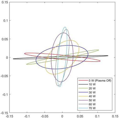
FIGURE 12. Experimental Lissajous figures produced from an elliptical fit of the Lissajous pattern X-Y scope detection at different heating powers.
Although the under-sampling and the phase difference due to cables different length do not allow a quantitative analysis, these results represent a fundamental demonstration of the instrument sensitivity to the plasma presence and to the power variation. This is an important “signature” of the capability of the polarimeter system and method to detect both the plasma ignition and the variation of the heating power (and the correlated electron density).
A rotation of almost 90° was observed and it seems to be in agreement to the gradually increasing of the optical emission vs. the pumping power observed by a simple visual inspection (pictures taken by the webcam shown in Figure 13).
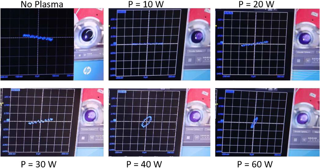
FIGURE 13. Visual inspection of the optical emission observed by a webcam thought a quartz window (on the right of each picture) in function of the pumping power. On the left of each picture is shown the screen of the scope and the corresponding Lissajous figure. The clockwise start with turn-off plasma.
Figure 13 shows that we are very sensitive to plasma ignition already at very low power 10W (see top left vs. top center), and in general to the power scan. Moreover, it shows the increase of the optical emission in a purely qualitative way (via a webcam), which is important preliminary feedback for this phase of the benchmark-test. Obviously, the multi-diagnostic system (described in Section 2) will allow to quantitatively characterize this emitted radiation (from visible, soft X, hard X, to gamma) to obtain the overall thermodynamical plasma properties by analyzing the experimental detected spectra. We do not report the spectra here because they are out of scope for the purpose of this paper. These preliminary tests represent a preliminary and necessary test before the next Faraday angle (and density) measurements that will be carried out thanks to a future setup upgrade (mixer for downshift the frequency and phase shifter to compensate the different lengths between the two channels).
All the techniques previously described allow the measurement of the average electron density along the line of sight. In this section we briefly describe an approach that allows the reconstruction of the density profile. In the perspective of the PANDORA setup, the microwave diagnostics tools are expected to be composed not only by polarimeters like the ones described above, but also including innovative techniques of plasma profile reconstruction along the line of sight. Analytical and numerical analyses have been performed up to now also to integrate the polarimetric and future profilometric in the PANDORA scenario Microwave/millimeter-waves inverse profiling requires the use of probing frequencies much higher than the cyclotron resonance and plasma frequency to consider plasma as transparent medium, avoiding anisotropy and strong scattering effects of waves propagating inside plasma. Such an assumption highly simplifies the formulation of the inverse scattering problem to be faced in performing inverse profilometry along the line-of-sight in plasma chamber. Under the above assumptions, plasma profiling can be afforded through the solution of a one-dimensional inverse scattering problem that requires the use of a large frequency bandwidth in order to gather a number of sufficient degrees of freedom of the scattered field data to be conveyed back by the retrieval process (Di Donato et al., 2019b). The numerical scattered field data has been simulated with a setup in 1D geometry resembling a beam propagation along the sight-line corresponding to the longitudinal axis of the plasma trap. In doing so, both the reflected and transmitted scattered field data have been gathered at two measurement points and the weak scattering Born approximation has been adopted to recover the plasma density profile as suggested in (Candès and Wakin, 2008). Finally, the recovery stage has been handled by means of a sparse reconstruction approach based on a “relaxed” version of the relaxed LASSO problem by the Compressive Sensing (CS) theory Candès and Wakin, 2008. Taking into account expected peak values of 1012 [cm−3] electron density at a ECR frequency of 18 GHz, 81 equispaced data samples in the frequency band 90−110 GHz is considered for the numerical benchmark resembling typical plasma profile shown in Figure 3B. The reconstruction results shown in Figure 14 is obtained exploiting prior support information on plasma region and slightly corrupting the scattered field data with white Gaussian noise. As it can be seen, the retrieved profile allows to roughly appraise the shape of plasma and its peak value, although a constant step-wise nature of the plasma profile is retrieved due to the assumption (not fully verified herein) about sparsity of the unknown.
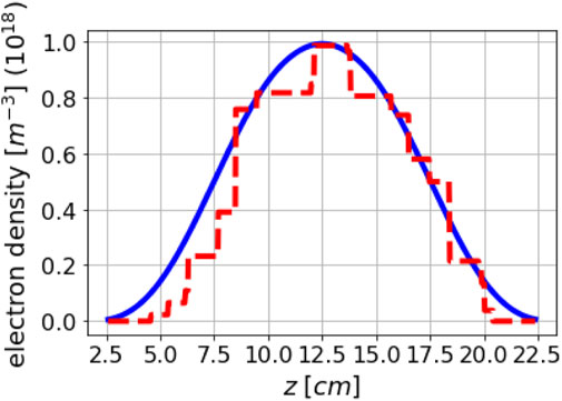
FIGURE 14. Typical numerical benchmark reconstruction of the electron density along the plasma chamber axis, the reconstruction is shown only in the core region of the chamber where the plasma density assumes largest values.
The preliminary simulations are encouraging (as confirmed in Figure 14); however, the challenge of this approach will be, also, the actual implementation of the experimental setup at high frequency and the required sensitivity.
In this paper, the preliminary design study of a mm-wave polarimeter for the PANDORA experiment, allowing plasma line-integrated electron density measurements, has been described. The optimum frequency range, two possible mm-wave schemes and a possible technical implementation are proposed and evaluated. Preliminary benchmark measurements at scaled microwave frequencies have been reported: 1) the first one was carried out employing a“free-space” setup by using a wire-grid polarizer and a rotable Ka-band OMT + horn antennas system; 2) the second one was directly implemented on a compact plasma trap (called Flexible Plasma Trap) installed at INFN-LNS and used as PANDORA down-sized testbench; schemes for the proposed PANDORA scenario have been investigated. In perspective, further testbench measurements will be performed by using probing frequency in the range 90–110 GHz (as designed for the PANDORA measurements) by procuring the whole polarimetric system, i.e., the new microwave components such as mixer and phase shifter.
The original contributions presented in the study are included in the article/supplementary material, further inquiries can be directed to the corresponding author.
GT, EN, and DM: mm-wave intefero-polarimeter design, study and simulation. PANDORA plasma chamber integration. Experimental measurements in free-space, Experimental measurements in plasma chamber. LD and GS: Experimental measurements in free-space, antenna simulations, profilometry simulations.
The authors wish to thank the 3rd Nat. Comm. of INFN, under the PANDORA Gr3, for the financial support. LD wish to thank project grant PLASMARE funded by University of Catania under research program Pia.ce.ri. 2020–2022.
The authors declare that the research was conducted in the absence of any commercial or financial relationships that could be construed as a potential conflict of interest.
All claims expressed in this article are solely those of the authors and do not necessarily represent those of their affiliated organizations, or those of the publisher, the editors and the reviewers. Any product that may be evaluated in this article, or claim that may be made by its manufacturer, is not guaranteed or endorsed by the publisher.
Biri, S., Pálinkás, J., Perduk, Z., Rácz, R., Caliri, C., Castro, G., et al. (2018). Multi-diagnostic setup to investigate the two-close-frequency phenomena. J. Instrum. 13, C11016. doi:10.1088/1748-0221/13/11/c11016
Candès, E. J., and Wakin, M. B. (2008). An introduction to compressive sampling [A sensing/sampling paradigm that goes against the common knowledge in data acquisition]. IEEE Signal Process. Mag. 25 (2), 21–30. doi:10.1109/msp.2007.914731
Cano, J. L., Villa, E., Teran, V., Gonzalez, E., de la Fuente, L., Artal, E., et al. (2015). “A w-band polarimeter for radio astronomy applications: Design and simulation,” in 2015 International Conference on Electromagnetics in Advanced Applications (ICEAA), Turin, Italy, 07-11 September 2015, 452–455. doi:10.1109/ICEAA.2015.7297152
Creely, A. J., Milanese, L. M., Tolman, E. A., Irby, J. H., Ballinger, S. B., Frank, S., et al. (2020). Design study of a combined interferometer and polarimeter for a high-field, compact tokamak. Phys. Plasmas 27, 042516. doi:10.1063/1.5142638
Di Donato, L., Mascali, D., Morabito, A. F., and Sorbello, G. (2019). A finite-difference approach for plasma microwave imaging profilometry. J. Imaging 5, 70. doi:10.3390/jimaging5080070
Di Donato, L., Morabito, A. F., Torrisi, G., Isernia, T., and Sorbello, G. (2019). Electromagnetic inverse profiling for plasma diagnostics via sparse recovery approaches. IEEE Trans. Plasma Sci. IEEE Nucl. Plasma Sci. Soc. 47, 1781–1787. doi:10.1109/tps.2019.2902469
Galata, A., Mascali, D., Mishra, B., Pidatella, A., and Torrisi, G. (2022). On the numerical determination of the density and energy spatial distributions relevant for in-plasma beta decay emission estimation. Front. Astronomy Space Sci. Nucl. Phys. Sect.
Gammino, S., Celona, L., Mascali, D., Castro, G., Torrisi, G., Neri, L., et al. (2017). The flexible plasma trap (FPT) for the production of overdense plasmas. J. Instrum. 12, P07027. doi:10.1088/1748-0221/12/07/p07027
Hartfuss, H. J., and Geist, T. (2013). Fusion plasma diagnostics with mm-waves: An introduction. Hoboken, New Jersey, US: Wiley VCH.
Heald, M. A., Wharton, C. B., and Furth, H. P. (1965). Plasma diagnostics with microwaves. Phys. Today 18, 72–74. doi:10.1063/1.3047729
Howard, A., Haberberger, D., Boni, R., Brown, R., and Froula, D. H. (2018). Implementation of a wollaston interferometry diagnostic on omega ep. Rev. Sci. Instrum. 89, 10B107. doi:10.1063/1.5036956
Li, X., Liu, Y., Xu, G., Zhou, T., and Zhu, Y. (2021). Design and characterization of a single-channel microwave interferometer for the helicon physics prototype experiment. Fusion Eng. Des. 172, 112914. doi:10.1016/j.fusengdes.2021.112914
Mascali, D., Naselli, E., and Torrisi, G. (2022). Microwave techniques for electron cyclotron resonance plasma diagnostics. Rev. Sci. Instrum. 93, 033302. doi:10.1063/5.0075496
Mascali, D., Santonocito, D., Amaducci, S., Andò, L., Antonuccio, V., Biri, S., et al. (2022). A novel approach to β-decay: Pandora, a new experimental setup for future in-plasma measurements. Universe 8, 80. doi:10.3390/universe8020080
Mauro, G. S., Celona, L., Torrisi, G., Pidatella, A., Naselli, E., Russo, F., et al. (2022). An innovative superconducting magnetic trap for probing β-decay in plasmas. Front. Phys. 10. doi:10.3389/fphy.2022.931953
Naselli, E., Mascali, D., Biri, S., Caliri, C., Castro, G., Celona, L., et al. (2019). Multidiagnostics setups for magnetoplasmas devoted to astrophysics and nuclear astrophysics research in compact traps. J. Instrum. 14, C10008. doi:10.1088/1748-0221/14/10/c10008
Naselli, E., Mascali, D., Torrisi, G., Castro, G., Celona, L., Gammino, S., et al. (2018). The first measurement of plasma density by means of an interfero-polarimetric setup in a compact ECR-plasma trap. J. Instrum. 13, C12020. doi:10.1088/1748-0221/13/12/c12020
Naselli, E., Santonocito, D., Amaducci, S., Galatà, A., Goasduff, A., Sebastiano, G., et al. (2022). Design study of a hpge detectors array for β-decays investigation in laboratory ecr plasmas. Frontiers 10. doi:10.3389/fphy.2022.935728
Pascual, J. P., Aja, B., Villa, E., Terán, J. V., de la Fuente, L., and Artal, E. (2021). Performance assessment of w-band radiometers: Direct versus heterodyne detections. Electronics 10, 2317. doi:10.3390/electronics10182317
Scime, E. E., Boivin, R. F., Kline, J. L., and Balkey, M. M. (2001). Microwave interferometer for steady-state plasmas. Rev. Sci. Instrum. 72, 1672–1676. doi:10.1063/1.1347971
Torrisi, G., Naselli, E., Mascali, D., Castro, G., Celona, L., Sorbello, G., et al. (2017). A new interferometric/polarimetric setup for plasma density measurements in compact microwave-based ion sources. J. Instrum. 12, C10003. doi:10.1088/1748-0221/12/10/c10003
Tudisco, O., Lucca Fabris, A., Falcetta, C., Accatino, L., De Angelis, R., Manente, M., et al. (2013). A microwave interferometer for small and tenuous plasma density measurements. Rev. Sci. Instrum. 84, 033505. doi:10.1063/1.4797470
Wiebold, M., and Scharer, J. E. (2009). “Non invasive measurement on the pulsed and steady-state , high power madhex helicon plasma thruster,” in The 31st International Electric Propulsion Conference (IEPC09), Ann Arbor, MI, USA, September 20–24, 2009.
Keywords: plasma diagnostics, interferometry, orthomode transducers, polarimeters, mm-wave, profilometry
Citation: Torrisi G, Naselli E, Mascali D, Di Donato L and Sorbello G (2022) Mm-wave polarimeter and profilometry design study for retrieving plasma density in the PANDORA experiment. Front. Astron. Space Sci. 9:949920. doi: 10.3389/fspas.2022.949920
Received: 21 May 2022; Accepted: 01 August 2022;
Published: 30 August 2022.
Edited by:
Siming Liu, Southwest Jiaotong University, ChinaReviewed by:
Jinlin Xie, University of Science and Technology of China, ChinaCopyright © 2022 Torrisi, Naselli, Mascali, Di Donato and Sorbello. This is an open-access article distributed under the terms of the Creative Commons Attribution License (CC BY). The use, distribution or reproduction in other forums is permitted, provided the original author(s) and the copyright owner(s) are credited and that the original publication in this journal is cited, in accordance with accepted academic practice. No use, distribution or reproduction is permitted which does not comply with these terms.
*Correspondence: G. Sorbello, Z2luby5zb3JiZWxsb0B1bmljdC5pdA==
Disclaimer: All claims expressed in this article are solely those of the authors and do not necessarily represent those of their affiliated organizations, or those of the publisher, the editors and the reviewers. Any product that may be evaluated in this article or claim that may be made by its manufacturer is not guaranteed or endorsed by the publisher.
Research integrity at Frontiers

Learn more about the work of our research integrity team to safeguard the quality of each article we publish.