 S. Tsikata
 L. Maunoury
 J-E. Ducret2
94% of researchers rate our articles as excellent or good
Learn more about the work of our research integrity team to safeguard the quality of each article we publish.
Find out more
TECHNOLOGY AND CODE article
Front. Astron. Space Sci., 17 August 2022
Sec. Nuclear Physics
Volume 9 - 2022 | https://doi.org/10.3389/fspas.2022.936532
This article is part of the Research TopicNuclear Physics and Astrophysics in Plasma TrapsView all 11 articles
The PANDORA (Plasmas for Astrophysics Nuclear Decays Observation and Radiation for Archaeometry) experiment aims to study the β-decay process inside a dense plasma mimicking stellar conditions. An electron cyclotron resonance plasma trap will be built at INFN-LNS in Catania, Italy, for the generation of the desired conditions in the laboratory. This type of non-equilibrium dense plasma (reaching densities of up to 1013 cm−3) is expected to generate electron energy distribution functions with electron energies ranging from tens of eV up to tens of keV. In this work, we describe aspects of a planned implementation of an incoherent Thomson scattering diagnostic for the study of electron properties in the plasma trap of PANDORA. The performance of this high-sensitivity diagnostic, known as THETIS, has been previously validated in measurements across a range of low-density magnetized plasma environments and it is expected to provide access to electron energy information in PANDORA in the range of temperatures from 1 to 103 eV. This article will establish the potential of such a diagnostic for future characterization of the electron properties in the PANDORA experiment.
Understanding β-decay processes in stellar conditions remains a challenge. Information on such processes can provide important clues regarding nucleosynthesis relevant to stars and the Big Bang. It has long been known that the β-decay rates for heavy ionized nuclides in stellar conditions differ significantly from those of neutrals seen on Earth, due to the partial occupations of the atomic electron orbitals of the ions, which can modify the available final states of the decay products such as the emitted electrons, and that the nature of this decay is affected by considerations such as the plasma density and temperature (Bahcall, 1962). These decay rates are also expected to potentially be influenced by the ionization states of nuclides; however, only limited experimental evidence for this is currently available, provided by experiments on storage rings, for example, in Ref. (Bosch et al., 1996).
To answer the myriad questions surrounding the role of the ionization states on nuclear decay processes in stellar conditions, an ambitious new experiment has been proposed, known as PANDORA (Plasmas for Astrophysics Nuclear Decays Observation and Radiation for Archaeometry) (Mascali et al., 2017; Mascali et al., 2020; Mascali et al., 2022). This project, initiated by the Italian National Institute of Nuclear Physics (INFN), aims to design and build a compact plasma trap enabling the study of stellar β-decay processes of isotopes. In addition to the development of a suitable trap reproducing the stellar-like electron densities and temperatures for the first time, this project will implement a range of diagnostic tools allowing plasma characterization and the monitoring of radionuclides. In this manuscript, we describe the proposed implementation of incoherent Thomson scattering (ITS) for the measurement of electron properties on PANDORA. Section 2 summarizes features of the PANDORA design. Thomson scattering principles and the main features of the diagnostic to be used in the future experiments are summarized in Section 3. Section 4 is devoted to the specificities of the PANDORA diagnostic implementation and the measurement ranges achievable. Conclusions are given in Section 5.
The PANDORA project will produce an electron cyclotron resonance plasma using a radiofrequency source. Plasma containment will be ensured by a magnetic field configuration consisting of superconducting hexapoles and solenoids, generating radial and axial magnetic fields, respectively. This configuration produces a minimum of the magnetic field of magnitude 0.4 T at the center of the chamber, with a maximum magnetic field ranging between 1.7–3 T at both ends of the chamber. The plasma chamber has an inner radius of 140 mm and length of 700 mm. Simplified schematics of the chamber are depicted in Figure 1, adapted from (Mascali et al., 2022), showing 1) the external iron yoke enclosing the plasma chamber, 2) hexapoles (in red) and solenoids (in blue), and 3) the cold mass in which the magnets are to be embedded. The lines of sight for γ-ray detectors and other diagnostics are positioned around the chamber. Radiofrequency waves are introduced into one end of the chamber using waveguides. The working gas is injected from the same end to generate an initial buffer plasma, followed by the injection of a particular isotope. Full details of the planned setup, instruments and experiments envisaged are available in (Mascali et al., 2022).
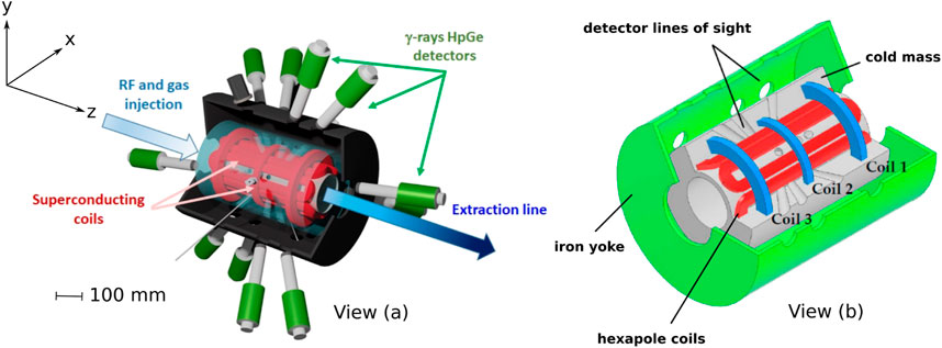
FIGURE 1. Schematics of the PANDORA chamber, in which an electron cyclotron resonance plasma will be created. View (A) shows a sectional view of the full experiment. View (B) shows details of the magnetic field configuration and its integration into the cold mass. Views (A,B) show the external iron yoke enclosing the plasma chamber, hexapoles (in red) and solenoids (in blue), and the cold mass in which the magnets are to be embedded. The lines of sight for γ-ray detectors and other diagnostics are also shown. Images have been adapted from (Mascali et al., 2022). A coordinate system has been defined in which z is coincident with the chamber axis and x and y are directions orthogonal to z.
The PANDORA experiment will generate a non-equilibrium, anisotropic plasma in which the electron densities ne are expected to range from 1011 to 1013 cm−3 and electron temperatures Te to range from 0.1 to 30 keV.
Thomson scattering describes the scattering of electromagnetic radiation by free charged particles (Froula et al., 2011). Information on the charged species dynamics and properties in plasmas is obtained via the analysis of the scattered field and differs according to two regimes. These regimes are identified according to a scattering parameter α, defined as
in which k is the observation wave number and λDe the electron Debye length. The observation wave vector k is defined according to the vector sum of the incident and scattering wave vectors, ki and ks respectively, and a scattering angle θ, as illustrated in Figure 2, which depicts scattering from a charge moving at a velocity v. The observation, scattering and incident frequencies are denoted by ω, ωs and ωi, respectively. The observation wave vector modulus is written
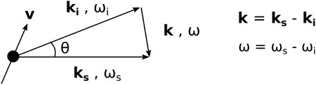
FIGURE 2. Definition of the observation wave vector k, as the vector sum of the incident (ki) and scattering (ks) wave vectors. Observation, scattering and incident frequencies are denoted by ω, ωs and ωi, respectively. The black dot depicts an arbitrary electron from which scattering occurs, moving at a velocity v.
or more simply, |k|≃ 2|ki| sin (θ/2), for non-relativistic charges where |ki|≃|ks|.
The angular frequency ω at a given measurement position reflects two Doppler shifts due to the particle motion: one due to particle motion towards the observation point (ks ⋅v), and the other due to particle motion towards the incident wave (ki ⋅v), i.e.,
As the scattered power per unit solid angle scales as the inverse of the square of the particle mass, the scattering from the free charges is dominated by the electrons, not the ions. For a small scattering parameter (α ≪ 1), the scattering is incoherent. The scattered field reflects thermal fluctuations of electrons, perceived at length scales shorter than the electron Debye length, and as such, the contributions of the individual electric fields are summed incoherently. The scattered spectrum in the incoherent regime can therefore be directly related to the electron properties in the plasma under investigation: the electron temperature or, more generally, the electron energy distribution function (EEDF), the electron density, and the macroscopic local electron drift velocity.
The electric field Es scattered from one electron is expressed as (Hutchinson, 2002)
written in terms of the incident electric field Ei, the electron radius re (2.82 × 10⁻¹⁵ m), and the far-field separation distance between the particle and the observation point R. Π is a tensor polarization operator. To express the scattered field in terms of the frequency spectrum Es (νs), we calculate the Fourier transform of Es (x, t) and take the incident Ei to be a monochromatic wave (i.e., supplied by a coherent laser source). The scattered frequency νs is given by ωs/2π. We obtain an expression for the scattered field from the electron which is written
In this expression, the particle is moving at a velocity v and is located at a position x with respect to an origin. The term κ (Hutchinson, 2002) is given by
The scattered power spectrum is directly proportional to the electron velocity distribution function fk (EVDF) measured along k. In the case of a Maxwellian distribution, the distribution function fk is written
where me represents the electron mass and vk the electron velocity in the direction of the observation wave vector.
The Gaussian spectrum width σ can then be used to directly deduce an electron temperature, using the expression
The electron density is proportional to the integral of the measured spectrum over the signal frequency, i.e., the greater the number of scatterers, the larger the amplitude of the scattered field. The absolute determination of this density is made using an appropriate calibration of spectra, typically from a Raman or Rayleigh spectrum. This calibration requires the measurement of the scattered signal amplitude with the same diagnostic configuration as for the intended Thomson scattering measurement (identical laser beam trajectory and dimensions, and identical configuration of the optics and acquisition system), with the chamber filled to a known gas pressure (density) in the absence of a plasma.
The ratio between the Raman or Rayleigh scattered power PR and Thomson scattered power PT can then be written
where dσT/dΩ and dσR/dΩ are the differential Thomson scattering cross-section and differential Raman or Rayleigh scattering cross-section, according to the method used. The ratio of scattered powers is equivalent to the ratio of the areas under the recorded spectra. Consequently, ne can be found.
A large scattering parameter (α ≫ 1) concerns the regime in which the observation length scale exceeds the electron Debye length. At such scales, the correlated behavior of particles can be perceived, and the resulting scattered spectra can reflect both electron and ion collective behavior. This collective behavior can provide information on features such as plasma waves. In this work, the implementation is restricted to the incoherent Thomson scattering regime. This implementation will involve the diagnostic known as THETIS (THomson scattering Experiments for low-Temperature Ion Sources). This diagnostic (Vincent et al., 2018) was conceived as a high-sensitivity new tool for investigations of electron properties in low-density plasmas (ne as low as 1010 cm−3). In the magnetized plasmas of devices such as Hall plasma thrusters, electron cyclotron resonance sources, and planar magnetrons used for thin film generation, there is a lack of suitable measurement capabilities for electron properties, which hinders device modeling and development. Overcoming this limitation was the motivation for the development of a new non-invasive, high-performance ITS diagnostic.
With regards to electron cyclotron resonance sources, a number of notable early applications of incoherent Thomson scattering to the investigations of these discharges were carried out in the 1990s (Sakoda et al., 1991; Bowden et al., 1993; Muraoka and Kono, 2011). The investigations on PANDORA will differ significantly from such prior studies. In addition to the different plasma parameters expected (PANDORA will feature higher densities and higher temperatures), the improved diagnostic capabilities now achievable provide new measurement opportunities.
The development of the THETIS diagnostic was initiated in 2015 in the framework of a new collaboration established by researchers at three French laboratories: S. Tsikata, ICARE, Orléans, CNRS; T. Minea, LPGP, Orsay, CNRS and O. Tuske, J. Fils, J. Schwindling, IRFU, Saclay, CEA. The compact diagnostic was successfully developed and applied to plasma source investigations at all three laboratories, confirming its value for electron property measurement in both pulsed and steady-state plasmas and the capacity for measurement in very low-density plasma environments (Tsikata et al., 2019; Vincent et al., 2020a; Vincent et al., 2020b).
A number of key features of the THETIS diagnostic are summarized in this section, with more extended discussions available in other articles, such as in Ref. (Vincent et al., 2018). A schematic of the diagnostic (optical bench and example implementation) is shown in Figure 3. The compactness of the optical bench (dimensions 0.75 × 1.5 m) was a key objective of the original design to facilitate investigations of multiple plasma sources at different laboratories.
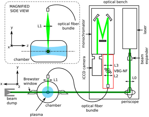
FIGURE 3. Main components of the THETIS optical bench, with an illustration of an example implementation on a vacuum vessel (views not to scale). This depiction shows the laser light (dark green) sent across a plasma (blue), with recovery and transmission of the scattered light (light green) for detection.
The main components of the diagnostic are: the radiation source, the optics for light guiding and focusing, the stray light filtering, the radiation dispersion and the light detection.
The incident radiation for scattering is provided by a pulsed, 532 nm-wavelength Nd:YAG laser with a nominal energy of 430 mJ per pulse and a 10 Hz repetition rate. The initial beam from this laser, 9 mm in diameter, is transmitted through a beam expander to increase the beam diameter by a factor of 3, in order to reduce the focused beam divergence in the plasma by the same factor.
High-reflectivity mirrors (reflectance
The THETIS diagnostic uses the recently-commercialized volume Bragg grating (Glebov et al., 2012) as a method of filtering stray radiation at 532 nm. The use of this element, in combination with a single monochromator, as opposed to the standard and widely-used triple grating spectrometer assemblies, e.g., in (Muraoka and Kono, 2011; Carbone and Nijdam, 2014), allows for improved photon transmission and detection, and hence, greater diagnostic sensitivity than is normally achievable. This technique of stray light filtering was first applied to Raman scattering measurements by Klarenaar in 2015 (Klarenaar et al., 2015) and implemented by us for incoherent Thomson scattering measurements (Vincent et al., 2018). This method is now being adopted by several other research groups.
The collected light is dispersed in wavelength using a spectrometer currently equipped with three gratings (2,400 lines/mm, 600 lines/mm and 300 lines/mm), all of which correspond to different degrees of spectral dispersion and hence, different ranges of accessible electron temperatures. This point will be revisited later in this paper.
An intensified charge coupled device (iCCD) camera is used to record light transmitted from the monochromator. The CCD dimensions are 1,024 × 1,024 imaging pixels (13.3 × 13.3 mm). The CCD, when cooled to -25 °C, registers a dark current of 2 e-/p/sec. The intensifier is a Gen III filmless type with a quantum efficiency of 50% at 500 nm. The equivalent background illumination of the intensifier is 0.002 e-/p/sec. Conventional photomultiplier tubes (Polyakov, 2013) have also been widely used for detection in incoherent Thomson scattering systems but have lower quantum efficiencies in the visible spectrum (10–30%).
As illustrated in Figure 3, the laser beam (entering with horizontal polarization) is directed across the vacuum chamber depicted in this figure, along x. The laser beam passes across fused silica windows mounted at Brewster angles, allowing transmission of the polarized light. In past implementations, these windows have been mounted at the ends of long tubes connected to the vacuum vessel, ensuring that any reflections from the windows are located far from the plasma volume of interest. Apertures to limit stray light propagation (not shown) have also been implemented along the path of the laser beam. The side view inset image illustrates the light collection at the top of the vacuum chamber (at 90° with respect to the laser line), using lens L1 positioned above a fused silica window for focusing onto the end of the optical fiber bundle, which subsequently transmits photons to the optical bench for filtering, dispersion and detection.
The implementation of the THETIS incoherent Thomson scattering diagnostic on PANDORA aims to provide access to local electron properties in a temperature and density range not readily accessible via other electron diagnostics to be implemented, while preserving a high spatial resolution and sensitivity. The electron populations generated in such a trap are expected to be comprised of three different electron groups, broadly classed as hot (kTe ∼ 100 keV), warm (kTe ∼ 100 eV - tens of keV) and cold (kTe ∼ 1–100 eV). Table 1, adapted from Ref. (Mascali et al., 2022), summarizes the electron temperature diagnostics to be implemented and their measurement ranges. As will be shown shortly, the features of the planned incoherent Thomson scattering implementation provide complementary information for the warm and cold electron temperature range in particular. In addition to these listed diagnostics, the electron density will be measured using line-integrated diagnostics tools: a W-band super-heterodyne polarimeter and microwave imaging.
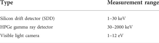
TABLE 1. Diagnostics for electron temperature measurement on PANDORA.
Figure 4 illustrates a schematic of the proposed implementation of incoherent Thomson scattering on PANDORA. A number of its key features will be highlighted.
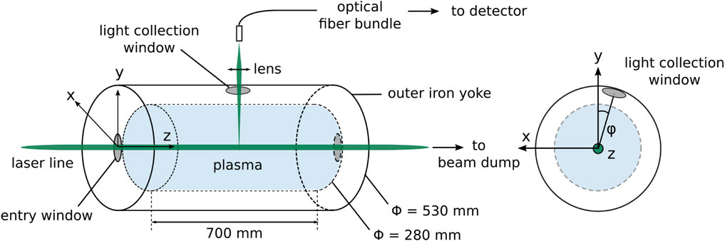
FIGURE 4. Planned laser beam access and scattered light recovery on PANDORA (not to scale), showing the longitudinal vessel view (at left) and section view (at right).
The incident laser will be transmitted along the axis of the chamber as shown in Figure 4 with horizontal polarization through fused silica windows. The entry window will be mounted such as to accommodate the presence of other components and connectors along the axis. Due to the presence of the exiting laser beam, it will be necessary to replace a combined mass spectrometer and Faraday cup intended for mounting at the end of the chamber with a simple fused silica window. Both input and exit windows will be mounted at Brewster angles. The available diameter for both windows will accommodate the laser beam, which will have a diameter of 27 mm on entering and will be focused using a 2000 mm-focal length lens to a waist in the plasma of 0.3 mm. This focused diameter has been judged to be sufficient for the purposes of the experiments, but can be modified as required.
The iron yoke depicted in Figure 4 has been designed with ports of diameter 88 mm providing 14 lines of sight converging on the center of the plasma, for the mounting of the γ-ray HPGe detectors. At present, the most likely scenario is that one of these ports will be reserved for the ITS photon collection (Figure 1). In the current design, the port to be used for light collection has an angle of inclination from y which is 22°. Based on the iron yoke radius and the size of the ports, the maximum solid angle ΔΩ, for the collection lens positioned at the light collection window located on the iron yoke, is at maximum 9.5°. In reality, this angle will be slightly reduced according to the restrictions on the placement of the lens (for example, due to the presence of connectors and instruments positioned on the iron yoke).
Based on the chamber dimensions, imaging characteristics for the collection optics can be selected. An aspheric lens of diameter 100 mm and focal length of 400 mm positioned at the light collection window will give an image distance to the optical fiber of 691 mm, which would be a suitable configuration. The volumetric resolution can be varied according to the number of fibers from which photons are collected (a volumetric resolution of 1 mm3, providing high spatial resolution and sufficient photon collection, has been achieved in past implementations).
The chamber windows, collection lens and optical fiber cores will be made of fused (amorphous) silica, due to the high transmission of visible radiation it offers. The nature of this experiment means that degradation of the transmission properties due to bombardment by γ-rays must be considered. Some evidence from past studies, such as in Ref. (Nagasawa et al., 1984; Colby et al., 2002), suggests that some modification of silica is to be expected, due to the creation of absorption bands in the visible spectrum, and is highly dependent on the radiation dose received. This feature will be examined in detail in the coming months, however, the spectral ranges of the measurement are not expected to be affected. It should be noted that the optical bench will not itself be located in close proximity to the plasma chamber.
The Bragg volume grating used for filtering of stray light at 532 nm (created by reflections off surfaces) offers a maximum theoretical attenuation factor of 104, within a narrow suppression band of width 0.3 nm. The narrowness of this band preserves much of the Thomson spectrum and thus ensures that measurements are possible even for cases where the electron temperature is below 1 eV. In the PANDORA implementation, stray light is likely to be encountered from surfaces within the plasma chamber, and the windows (entry, exit and collection). The level of stray light is difficult to predict before the setup of the experiment, however, to ensure stray light mitigation, the option of using a second volume Bragg grating in series with the first will be provided. This can easily be integrated into the proposed implementation as needed.
On PANDORA, the scattering parameter α can be determined from the expected plasma parameters. The electron Debye length on PANDORA is determined as
where ϵ0 is the permittivity of free space, kB is the Boltzmann constant, and qe the elementary charge. On PANDORA, based on the expected range of electron temperatures (Te: 0.1–30 keV) and electron densities (ne: 1011–1013 cm−3), an upper and lower bound for the Debye length can be calculated. This is found to be:
The observation wavenumber k is calculated from the laser wavenumber ki (the inverse of the laser wavelength) and the observation angle θ, using the relation k ≈ 2ki sin (θ/2) given earlier. The angle θ corresponds to 78° in the configuration used for PANDORA, according to the observation port likely to be available. The calculated observation wavenumber k is 2 × 10⁶ m−1.
The value α = 1/(kλD) is therefore in the range
i.e., α ≪ 1, hence for all conditions of the Thomson scattering implementation, observations will correspond to the incoherent regime.
The spectral dispersion will be achieved with a Princeton Instruments Acton Standard Series SP-2756 imaging spectrograph, with detection provided by a Princeton Instruments PI-MAX 4: 1024f iCCD camera. The use of different gratings during the recording of the scattered spectra results in different ranges of wavelength (or frequency) which can be perceived. Table 2 summarizes a list of gratings of the spectrometer (2400, 600 and 300 lines/mm currently used, 150 lines/mm an option to be provided for PANDORA investigations) and the corresponding resolutions and electron energies accessible by the combined spectrometer and camera system.
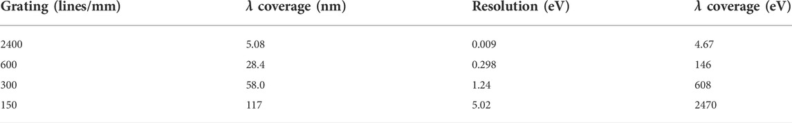
TABLE 2. Accessible electron energies and detection resolution based on choice of spectrometer grating.
The equivalence between the electron velocity v and the wavelength shift Δλ which can be perceived can be expressed as
And the corresponding wavelength coverage expressed as electron energy is determined as
As Table 2 shows, decreasing the number of lines/mm of the grating used decreases the electron temperature resolution but increases the wavelength coverage. We may identify the spectrum width (Gaussian standard deviation) as Δλe, depicted in Figure 5. Figure 5 illustrates Thomson spectra (green profiles) acquired with the laser wavelength λi 1) centered in the spectral range, and 2) shifted. The vertical axis represents the number of photon counts recorded by the camera, an amplitude dependent on the wavelength, written as I(λ), and ΔλT the full accessible wavelength range. The gray bar depicts the regions where spectral information is blocked due to the presence of the volume Bragg grating notch filter. As depicted in Figure 5, the recording of the Thomson spectra allows for the centering of the laser wavelength within the spectral range, or the shifting of the position of this central wavelength in order to access larger electron temperatures. Using option 2) would result, at maximum, in a doubling of the achievable λ coverage shown in Table 2.
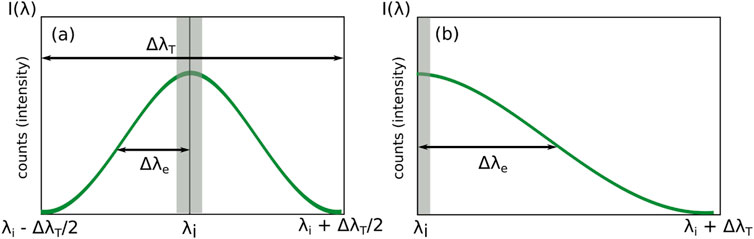
FIGURE 5. Illustration of Thomson spectra (green lines) acquired with (A) the laser wavelength λi centered in the spectral range or (B) shifted, to access a larger spectra range. The gray bar depicts the regions where spectral information is blocked due to the presence of the volume Bragg grating notch filter. The vertical axis represents the number of photon counts recorded by the camera, an amplitude dependent on the wavelength, written as I(λ). The full spectral range accessible is ΔλT and the Gaussian standard deviation is shown as Δλe.
The normalized electron energy distribution function f(E) is obtained from the scattering spectrum using the expression (Vincent et al., 2018):
where Δλ is a given wavelength shift with respect to the central laser frequency,
The calculation of the electron energy distribution function requires a sufficiently large signal to noise ratio, as any artifacts or noise present in the spectrum result in distortions of the calculated EEDF due to the application of the derivative. A Savitzky-Golay (Savitzky and Golay, 1964) smoothing procedure can be applied to the acquired spectra to render the subsequent EEDF calculation less noisy. The wings of the spectra, where the signal to noise ratio is low, can be particularly challenging to resolve, whereas the central portion of the spectrum (representing the bulk electron energies) can be more readily be used in the calculation of the EEDF.
The implementation of future Thomson scattering measurements will be performed according to the following procedures: Table 3.
1) Optical bench setup: the diagnostic will be installed on PANDORA according to the provisional implementation described in this paper. The installation will accommodate the constraints of the final plasma vessel configuration (accessible ports, presence of other instruments, and so on).
2) Measurement types: For a given experimental condition, a number of spectrum types must be recorded in order to obtain the final Thomson scattered spectrum (Table 3). These spectra contain several contributions: 1) the Thomson scattered signal, 2) stray light (centered at the laser wavelength), 3) natural plasma emission, 4) noise inherent to the camera photodetector, and, depending on the configuration, 5) fluorescence from solid interfaces. The combination of these spectrum types allows for the calculation of the final Thomson spectrum. This is obtained using the following form if fluorescence is present:
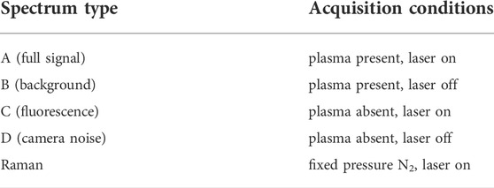
TABLE 3. Conditions used for signal acquisitions.
In the absence of fluorescence, the final Thomson spectrum is obtained from
A Raman scattering spectrum is recorded for the purposes of calibration, with the chamber filled to a known pressure of a gas such as nitrogen, without the plasma present. It is worth mentioning that spectrum acquisitions have been carried out using this diagnostic in a photon accumulation mode, whereby the recorded scattered photons over multiple laser shots (6000) have been summed on the detector in order to constitute a single spectrum. Given the laser repetition rate of 10 Hz, this corresponds to individual spectrum records of 10-min duration. It will be necessary to measure spectra on a fully stabilized or reproducible pulsed plasma on PANDORA in order to accommodate this measurement duration.
3) Measurement conditions: an experimental protocol for the investigation of β-decay has been outlined in Ref. (Mascali et al., 2022), in which a buffer plasma is generated, then injected with different isotopes which are ionized to produce a dense plasma. The role of the incoherent Thomson scattering experiment will be to probe electron properties at the core of the plasma generated, under conditions which will include: 1) varying injected radiofrequency power, 2) varying magnetic field configurations, 3) varying isotope types, among others. As shown earlier in this section, the electron temperatures measurable will range from the 1 eV–103 eV range (Table 2), providing information which complements the range accessible to the other electron diagnostics (Table 1).
In this manuscript, a concise analysis of the potential application of a recently-developed incoherent Thomson scattering diagnostic known as THETIS has been made for the PANDORA experiment. This diagnostic is notable for its high sensitivity (giving access to information on plasma environments where densities are as low as 1010 cm−3) and its application to PANDORA would provide an important addition to the array of electron diagnostics techniques needed for the characterization of the plasmas produced in PANDORA. It is expected that electron temperatures in the range of 1 eV–103 eV (cold and warm electrons) may be measured by this diagnostic in the future implementation. The non-invasive nature of the diagnostic and its ability to reflect direct information on electron properties will be particularly valuable.
The original contributions presented in the study are included in the article. Further inquiries can be directed to the corresponding authors.
ST undertook the writing of the article and implementation proposal, with contributions on the PANDORA configuration provided by LM and J-ED.
ST thanks the LPGP (T. Minea), CEA Saclay and CNES for support of the THETIS diagnostic development.
The authors declare that the research was conducted in the absence of any commercial or financial relationships that could be construed as a potential conflict of interest.
All claims expressed in this article are solely those of the authors and do not necessarily represent those of their affiliated organizations, or those of the publisher, the editors and the reviewers. Any product that may be evaluated in this article, or claim that may be made by its manufacturer, is not guaranteed or endorsed by the publisher.
Bahcall, J. N. (1962). Beta decay in stellar interiors. Phys. Rev. 126, 1143–1149. doi:10.1103/physrev.126.1143
Bosch, F., Faestermann, T., Friese, J., Heine, F., Kienle, P., Wefers, E., et al. (1996). Observation of bound-state β- decay of fully ionized 187 Re: 187 Re - 187 Os cosmochronometry. Phys. Rev. Lett. 77, 5190–5193. doi:10.1103/physrevlett.77.5190
Bowden, M. D., Okamoto, T., Kimura, F., Muta, H., Uchino, K., Muraoka, K., et al. (1993). Thomson scattering measurements of electron temperature and density in an electron cyclotron resonance plasma. J. Appl. Phys. 73, 2732–2738. doi:10.1063/1.353046
Carbone, E., and Nijdam, S. (2014). Thomson scattering on non-equilibrium low density plasmas: Principles, practice and challenges. Plasma Phys. control. Fusion 57, 014026. doi:10.1088/0741-3335/57/1/014026
Colby, E., Lum, G., Plettner, T., and Spencer, J. (2002). Gamma radiation studies on optical materials. IEEE Trans. Nucl. Sci. 49, 2857–2867. doi:10.1109/tns.2002.806019
Froula, D. H., Glenzer, S. H., Luhmann, N. C. J., and Sheffield, J. (2011). Plasma scattering of electromagnetic radiation: Theory and measurement techniques. Elsevier.
Glebov, A. L., Mokhun, O., Rapaport, A., Vergnole, S., Smirnov, V., and Glebov, L. B. (2012). Volume Bragg gratings as ultra-narrow and multiband optical filters. Proc. SPIE 8428, 84280C.
Hutchinson, I. H. (2002). Principles of plasma diagnostics. 2 edn. Cambridge University Press. doi:10.1017/CBO9780511613630
Klarenaar, B. L. M., Brehmer, F., Welzel, S., Van Der Meiden, H. J., van de Sanden, M. C. M., and Engeln, R. (2015). Note: Rotational Raman scattering on CO2 plasma using a volume Bragg grating as a notch filter. Rev. Sci. Instrum. 86, 046106. doi:10.1063/1.4918730
Mascali, D., Busso, M., Mengoni, A., Amaducci, S., Giuseppe, C., Celona, L., et al. (2020). The PANDORA project: An experimental setup for measuring in-plasma β-decays of astrophysical interest. EPJ Web Conf. 227, 01013. doi:10.1051/epjconf/202022701013
Mascali, D., Musumarra, A., Leone, F., Romano, F. P., Galata, A., Gammino, S., et al. (2017). PANDORA, a new facility for interdisciplinary in-plasma physics. Eur. Phys. J. A 53, 145. doi:10.1140/epja/i2017-12335-1
Mascali, D., Santonocito, D., Amaducci, S., Andò, L., Antonuccio, V., Biri, S., et al. (2022). A novel approach to β-decay: PANDORA, a new experimental setup for future in-plasma measurements. Universe 8, 80. doi:10.3390/universe8020080
Muraoka, K., and Kono, A. (2011). Laser Thomson scattering for low-temperature plasmas. J. Phys. D. Appl. Phys. 44, 043001. doi:10.1088/0022-3727/44/4/043001
Nagasawa, K., Tanabe, M., and Yahagi, K. (1984). Gamma-ray-induced absorption bands in pure-silica-core fibers. Jpn. J. Appl. Phys. 23, 1608–1613. doi:10.1143/jjap.23.1608
Polyakov, S. V. (2013). “Photomultiplier tubes,” in Experimental methods in the physical Sciences (Elsevier), 69–82.
Sakoda, T., Momii, S., Uchino, K., Muraoka, K., Bowden, M., Maeda, M., et al. (1991). Thomson scattering diagnostics of an ECR processing plasma. Jpn. J. Appl. Phys. 30, L1425–L1427. doi:10.1143/jjap.30.l1425
Savitzky, A., and Golay, M. J. E. (1964). Smoothing and differentiation of data by simplified least squares procedures. Anal. Chem. 36, 1627–1639. doi:10.1021/ac60214a047
Tsikata, S., Vincent, B., Minea, T., Revel, A., and Ballage, C. (2019). Time-resolved electron properties of a HiPIMS argon discharge via incoherent Thomson scattering. Plasma Sources Sci. Technol. 28, 03LT02. doi:10.1088/1361-6595/ab0c67
Vincent, B., Tsikata, S., and Mazouffre, S. (2020). Incoherent Thomson scattering measurements of electron properties in a conventional and magnetically-shielded Hall thruster. Plasma Sources Sci. Technol. 29, 035015. doi:10.1088/1361-6595/ab6c42
Vincent, B., Tsikata, S., Mazouffre, S., Minea, T., and Fils, J. (2018). A compact new incoherent Thomson scattering diagnostic for low-temperature plasma studies. Plasma Sources Sci. Technol. 27, 055002. doi:10.1088/1361-6595/aabd13
Keywords: incoherent Thomson scattering, electron density, laser diagnostics, electron temperature, electron cyclotron resonance (ECR), stellar plasmas, magnetic trap
Citation: Tsikata S, Maunoury L and Ducret J-E (2022) Incoherent Thomson scattering: future implementation and measurement capabilities on the PANDORA experiment. Front. Astron. Space Sci. 9:936532. doi: 10.3389/fspas.2022.936532
Received: 05 May 2022; Accepted: 13 July 2022;
Published: 17 August 2022.
Edited by:
David Mascali, Laboratori Nazionali del Sud (INFN), ItalyReviewed by:
Mitchell L. R. Walker, Georgia Institute of Technology, United StatesCopyright © 2022 Tsikata, Maunoury and Ducret. This is an open-access article distributed under the terms of the Creative Commons Attribution License (CC BY). The use, distribution or reproduction in other forums is permitted, provided the original author(s) and the copyright owner(s) are credited and that the original publication in this journal is cited, in accordance with accepted academic practice. No use, distribution or reproduction is permitted which does not comply with these terms.
*Correspondence: S. Tsikata, c2VkaW5hLnRzaWthdGFAY25ycy1vcmxlYW5zLmZy; L. Maunoury, bGF1cmVudC5tYXVub3VyeUBnYW5pbC5mcg==
Disclaimer: All claims expressed in this article are solely those of the authors and do not necessarily represent those of their affiliated organizations, or those of the publisher, the editors and the reviewers. Any product that may be evaluated in this article or claim that may be made by its manufacturer is not guaranteed or endorsed by the publisher.
Research integrity at Frontiers
Learn more about the work of our research integrity team to safeguard the quality of each article we publish.