 Joseph E. Borovsky
 Gian Luca Delzanno
 Kateryna N. Yakymenko
94% of researchers rate our articles as excellent or good
Learn more about the work of our research integrity team to safeguard the quality of each article we publish.
Find out more
ORIGINAL RESEARCH article
Front. Astron. Space Sci., 02 February 2022
Sec. Space Physics
Volume 9 - 2022 | https://doi.org/10.3389/fspas.2022.810792
This article is part of the Research TopicCoupled Feedback Mechanisms in the Magnetosphere-Ionosphere SystemView all 25 articles
In the Earth’s dipole magnetosphere finite-gyroradius effects produce a shift of the atmospheric loss cone away from the direction of the magnetic field. This loss-cone shift is theoretically described by the “Mozer transform” [Mozer, F. S. (1966). Proton trajectories in the radiation belt. J. Geophys. Res. 71:2701], which is based upon the curvature drift of particles crossing the equatorial plane. For positive ions the northern and southern loss cones both shift westward and for electrons the northern and southern loss cones both shift eastward. This loss-cone shift is part of a coordinate-system transform, with the transformed coordinates better organizing the behavior of particle orbits in the dipole magnetic field (e.g. first adiabatic invariants, mirror heights, and bounce times). In this report it is demonstrated that the transformed coordinate system also properly organizes pitch-angle diffusion. This improved organization of the diffusion is true whether the angular scattering is produced by plasma-wave scattering or by field-line-curvature (FLC) scattering. It is shown that FLC scattering and the loss cone shift are linked, so that if FLC scattering is occurring, there is a loss cone shifted away from the magnetic-field direction and the Mozer-transformed coordinates are needed.
For energetic charged particles in the Earth’s dipole magnetic field a finite-gyroradius effect causes the atmospheric loss cone to shift away from the direction of the magnetic field (Porazik et al., 2014; Borovsky et al., 2022). Defining the equatorial pitch angle αo to be the angle between the particle’s velocity vector when it crosses the equatorial plane and the equatorial magnetic-field vector, this shift means that the loss cone is not centered at αo = 0o as it is for very-low-energy particles. For positive ions the northern and southern loss cones both shift westward and for electrons the loss cones both shift eastward. Note that with this shift the two loss cones are no longer 180o apart.
The loss-cone shift (aberration) is simply described using the “Mozer transform” (Mozer, 1966), which points out that the angular shift is
where vo is the particle’s total velocity, v|| is the component of the particle’s velocity that is parallel to the magnetic field, and vcurve is the curvature drift velocity of the particle
[cf. eq. (2.17) of Roederer and Zhang (2014)], where m is the mass of the particle, q the signed charge of the particle, c the speed of light, and γ = (1−(vo2/c2))−1/2 is the relativistic factor. At the equator of the dipole magnetic field, the curvature drift speed is
where r is the distance from the dipole center. Borovsky et al. (2020a,b) used the Mozer transform to explore the loss cone shift for space experiments with energetic electron beams. Borovsky et al. (2022) extensively explored the loss-cone shift and the organization of particle-orbit properties using the Mozer transform. Earlier Porazik et al. (2014) explored the loss-cone shift in a more-complicated fashion using the Gardner-expansion (Gardner, 1966) for the first adiabatic invariant μ. (See also Sanchez et al. (2019), Powis et al. (2019), and Willard et al. (2019) for discussions of the loss-cone shift in terms of the Gardner expansion.)
Looking beyond the shift of the loss cone, in this paper an angular coordinate system will be explored that organizes the behavior of energetic ions and electrons bouncing in the Earth’s dipole. This coordinate system differentially aberrates the standard equatorial pitch-angle αo gyrophase-angle ϕo coordinate system, with the aberration angle being maximum for the center of the loss cone near αo = 0o and the aberration angle going to zero for αo = 90o particles. It will be shown in particular that this aberrated coordinate system better describes the action of the pitch-angle scattering (angular scattering) of particles in the dipole than does the standard αo−ϕo coordinate system.
In the low-energy limit (the zero-gyroradius limit) the contours of equal mirror height (and the atmospheric loss cone) are concentric circles in αo−ϕo (pitch angle - gyrophase angle) coordinates as seen from the equatorial plane. The centers of these low-energy circles are all at αo = 0o, which is the direction of the magnetic field. Further, in that low-energy limit the instantaneous value of the first-adiabatic invariant μ = γmv⊥2τg at the equatorial plane is equal to μ = γmv⊥2τg at the mirror point [where τg is the particle’s gyroperiod and v⊥ = vosin (α)]. (Note that, as in Borovsky et al. (2022), the definition of the first adiabatic invariant from the action integral μ = ∫ P⊥•dL = (1/2)∫ γmv⊥2 dt for the gyromotion [cf. eq. (12.64) of Jackson (1975)] is used rather than the magnetic moment, where P⊥ is the transverse-to-B canonical momentum and where the integral is over a full gyroperiod: the two definitions of μ differ by the constant mc/q.) For energetic particles in a dipolar magnetic field, finite-gyroradius effects make μ = (1/2) γmv⊥2τg and μ = (1/2)∫ γmv⊥2 dt not useful for describing orbits (Borovsky et al., 2022). This was clearly pointed out by Mozer (1966) and by Il’in et al. (1992) where part of the particle’s perpendicular velocity v⊥ does not participate in gyromotion and mirroring. Because of finite-gyroradius effects, for energetic particles in a dipolar (or stretched) magnetic field the polar coordinate system α - ϕ becomes distorted. An aberrated coordinate system better organizes the properties of particle orbits in terms of equatorial αo and ϕo. This aberrated coordinate system organizes bounce periods, values of μ = γmv⊥2τg at the mirror points, and the mirror height (Borovsky et al., 2022). The aberrated coordinate system also locates the atmospheric loss cone, which is aberrated (displaced) away from 0o equatorial pitch angle. In the aberrated coordinate system, the angular area of loss cone as seen from the equatorial plane stays approximately constant. Note that the amount of aberration of the coordinate system depends on the kinetic energy and mass of the particle [cf. expressions (Eq. 1) and (Eq. 3)].
The coordinate system is explored by integrating particle orbits in the Earth’s dipole magnetic field. The equations
where r = (x, y, z) is the location of the particle, q is the charge of the particle, m is the mass of the particle, c is the speed of light, v is the particle’s velocity vector, γ = [1−(v2/c2)]−1/2 is the relativistic factor, B = B (r) is the magnetic field vector at the location of the particle, and M = ×7.951025 G cm3 is the dipole moment of the Earth. Expressions (4) are numerically solved with a time-centered predictor-corrector scheme with a typical time step of 2.5 × 10⁻⁸ s for protons.
Following Mozer’s logic, the aberration angle for the coordinate system is found to be governed by the curvature drift speed vcurve at the equator [cf. expression (Eq. 1)], which is a function of the particle velocity, the particle’s equatorial pitch angle αo, and the particle’s distance r from the dipole center [cf. expression (Eq. 3)]. Mozer’s transformation can be demonstrated by looking at the orbit of a particle with initial velocity at the equatorial plane such that v⊥ = vcurve. This orbit exhibits no gyromotion and indeed it is at the center of the aberrated equatorial loss cone. (In the literature, this orbit with v⊥ = vcurve at the equatorial plane has been denoted as the “central trajectory” (Il’in et al. (1992); Il’ina et al., 1993; Borovsky et al., 2022).) As a single mirroring particle in the Earth’s magnetic field repeatedly crosses the equatorial plane, its direction vector repeatedly lies on an aberrated circle in αo−ϕo coordinates. Each time the particle crosses the equatorial plane, the particle’s phase angle on that circle advances by the same increment. Hence one can assume that particles mirroring in a dipole are “gyrotropic” on each aberrated circle. This is demonstrated in Figure 1, where the (αo, ϕo) coordinates of nine different 700-keV protons injected at the geosynchronous-orbit equator are plotted as each proton repeatedly crosses the equatorial plane traveling northward. The initial (αo, ϕo) coordinates of the nine ions were (3o, 270o) (red points), (2o, 270o) (orange points), (0o, 270o) (yellow points), (2o, 90o) (light-green points), (7o, 90o) (green points), (12o, 90o) (light-blue points), (17o, 90o) (blue points), (22o, 90o) (purple points), and (27o, 90o) (black points). Note that the (αo, ϕo) equatorial crossing points of each ion lie on a circle. Each time an ion crosses the equatorial plane, the phase angle on its circle increases by the same fixed amount: this constant added phase angle gives rise to the clumping patterns of the points in Figure 1. Note that the circles of Figure 1 are aberrated away from αo = 0o in the direction of ϕo = 270o (westward).
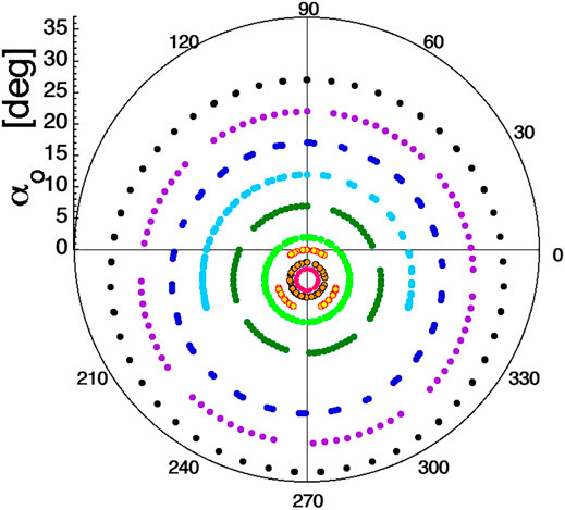
FIGURE 1. For nine 700-keV protons launched at the geosynchronous orbit (L = 6.6) equator with nine different initial equatorial pitch angles, the pitch angle αo and gyrophase angle ϕo of the protons at the times of their northward-going equatorial crossings is plotted. The magnetic-field direction vector is at αo = 0o, where the black cross-hairs intersect.
It is instructive to look at these equatorial-crossing coordinates in Cartesian (αo,ϕo) coordinates. In Figure 2 the northward-traveling equatorial-plane crossings of 21 different 700-keV protons at geosynchronous orbit are plotted. Note that the displaced (aberrated) circles of Figure 1 become wavy curves in Figure 2. Note also that the waviness of the curves in Figure 2 decreases as the equatorial pitch angle αo → 90o. This indicates that the transformation of the equatorial (αo,ϕo) coordinates from the αo = 0o direction that organizes the orbits is not a simple rotation, but rather differential rotation with the rotation being largest near the central trajectory and the loss cone and the rotation being zero at αo = 90o.
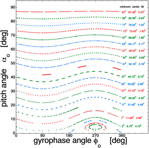
FIGURE 2. The αo and ϕo coordinates of the northward-going equatorial crossings of twenty 700-keV protons at geosynchronous orbit (Figure 1) are plotted in Cartesian fashion.
For each curve of Figure 2, the tilt angle θtilt of each circle in Figure 1 is plotted in Figure 3 as a function of the minimum pitch angle αmin of that circle. For each wavy curve in Figure 2, the tilt angle is given by θtilt = (αmax−αmin)/2. For the closed contours in Figure 1, the αo angles are plotted as negative values. Figure 3 clearly shows that the tilt (aberration) angle is maximum for the loss-cone center and the tilt goes to zero for αo = 90o. The red curve in Figure 3 is arctan (vcurve/v||) at the equator, where for the 700-keV protons at L = 6.6 the quantities are vcurve = cos2α 9.47 × 107 cm/s and v|| = cosα 1.159 × 109 cm/s. The blue curve is 1.014 times the red curve. (It is not known why multiplying by 1.014 yields a better fit.) As can be seen, these curves fit the black data points in Figure 3 fairly well and so the formula
can be used to calculate the aberration (tilt) of the coordinate system relative to the standard αo−ϕo coordinates.
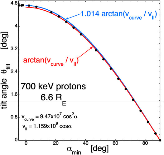
FIGURE 3. The data from Figure 2 is plotted and fitted. (See text for an explanation.)
Note that in θtilt = arctan (vcurve/v||), the gradient-B drift vgrad = sin2α 4.36 × 107 cm/s does not seem to play a role in the aberration of the improved coordinate system. This is observed in the analysis of the particle orbits, but is not yet fully understood. Borovsky et al. (2022) demonstrated that the sum of the curvature drift vcurve plus the gradient drift vgrad is the proper numerator in the Mozer transform [expression (Eq. 1)] for better conservation of the first adiabatic invariant μ = γmv⊥2τg.
As seen in Section 2, the equatorial-crossing circles aberrated by the Mozer transform organize the behavior of the orbits and the loss cone. When angular scattering is added along the ion’s orbit away from the equator, the aberrated circles also organize the description of the scattering in equatorial pitch-angle and gyrophase-angle coordinates. This is demonstrated in Figure 4. In Figure 4 the (αo,ϕo) coordinates at the equatorial crossings of 1,000 protons are shown. Each proton is launched northward from the dipole equator at r = 6.6 RE with an αo = 1o pitch angle at a gyrophase angle of ϕo = 90o and with a kinetic energy of 700 keV. The launch angles (αo,ϕo) = (1o, 90o) of the 1,000 protons are plotted as the large red point in Figure 4. Each proton, when it has traveled for exactly a time 2.282 s (halfway in time to its first mirror point), is given a 3o deflection in its velocity vector in a random direction normal to its instantaneous velocity vector, keeping its kinetic energy constant. (This could represent the interaction of the particle with some wave along the particle’s orbit, although in a very controlled and idealized way.) The equatorial pitch angles and gyrophase angles of the first northward equatorial crossings of the 1,000 protons that each experienced a single 3o deflection are plotted as the blue points in Figure 4. The black circle in the figure is the circle that unscattered (unperturbed) protons make as they bounce and cross the equatorial plane. As seen in Figure 4, the aberrated black circle is uniformly broadened by off-equatorial pitch-angle scattering, and the black aberrated circle organizes the behavior (diffusion) of the non-equatorial scattering in equatorial pitch angle and gyrophase angle.
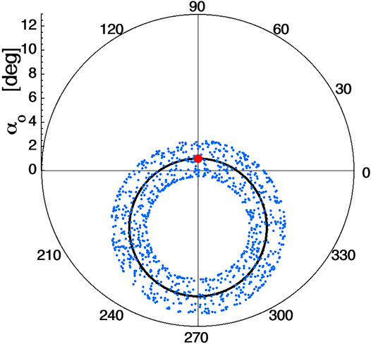
FIGURE 4. For 1,000 protons of energy 700-keV all launched from the equatorial plane at L = 6.6 with (αo, ϕo) = (1o, 90o) (marked with the large red dot), the (αo, ϕo) values for the first northward-going equatorial crossing is plotted as a blue point. Each ion was subjected to a 3o deflection when it was halfway to its first mirror point. The black circle is the circle of (αo, ϕo) values for ions that are not subjected to angular scatterings.
Another form of angular scattering is field-line-curvature (FLC) scattering. FLC scattering is parameterized by the “adiabaticity parameter” ε = rgyro/Rc at the equator, where rgyro is the gryroradius of the particle with pitch angle 90o and Rc is the equatorial radius of curvature of the field lines. ε = rgyro/Rc = 3γmcvo/eB is related to the loss-cone shift at the equator θtilt = arctan (vcurve/v||) = arctan (3γmcvo cos (αo)/eB). At small angles αo, ε ≈ θtilt. Hence, the strength of FLC scattering is parameterized by the size of the loss-cone tilt (Borovsky et al., 2022). If the ε = rgyro/Rc value of a particle is larger than 0.1–0.2, the particle begins to stochastically scatter each time it crosses the equatorial region of the dipole (e.g. Dragt and Finn, 1976; Birmingham, 1984; Tagare, 1986; Jung and Sholz, 1988; Chrikov, 1987; Anderson et al., 1997; Young et al., 2002, 2008; Artemyev et al., 2015; Borovsky et al., 2022). An example of this is shown in Figure 5, where five protons with five different kinetic energies are launched at the geosynchronous-orbit equator with initial equatorial pitch angle of 0o. The northward-traveling equatorial crossings of the five protons are plotted as the points in Figure 5. The colors are 700 keV (ε = 0.08) in red, 1 MeV (ε = 0.113) in green, 1.4 MeV (ε = 0.16) in blue, 2 MeV (ε = 0.23) in orange, and 2.8 MeV (ε = 0.32) in purple. As can be seen, with increasing energy the westward angular tilt of the loss cone increases since vcurve/vo in expression (Eq. 1) is approximately proportional to vo and vo ∝ E1/2, with E being the kinetic energy. At energies of 2-MeV and higher in the figure a scattering of the crossings can be seen. (also Figure 6 of Borovsky et al., (2022).). Note in Figure 5 that the aberrated circles organize the FLC scattering as they did the off-equatorial angular scattering in Figure 4. As pointed out in Borovsky et al., (2022), FLC scattering and the loss-cone shift are both finite-gyroradius effects and the two are linked. Hence, if FLC scattering (values of ε ≥ 0.15) is occurring, there is also a shift of the loss cone (θshift ≥ 10o).
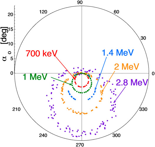
FIGURE 5. Five protons with five different kinetic energies (colors) are launched from the geosynchronous-orbit equator with αo = 0o and the (αo, ϕo) values of their northward-gong equatorial crossings are plotted as the points.
One might worry that if FLC scattering is going on and first adiabatic invariants are being broken, that the Mozer transform [expression (Eq. 1)] does not work because the concept of calculating the curvature drift is a guiding-center concept and that is being violated. This is extensively explored in Borovsky et al. (2022). The Mozer transform accurately predicts the loss cone shift for shift values up to about 10o, which are ε values of about 0.15 or less. As ε increases further (where FLC scattering commences), the loss-cone shift in pitch angle deviates slightly from the prediction of the Mozer transform and the loss-cone shift picks up an earthward component in gyrophase angle. When epsilon goes beyond about 0.5, the Mozer transform looses accuracy in predicting the loss-cone shift, but in this ε > 0.5 regime the shift angle still increases monotonically as ε increases. Even though with FLC scattering occurring the first adiabatic invariants are breaking upon crossing the equator, a particle’s kinetic energy and its ε value are both conserved and the loss cone for that particle has the same shift as seen from the equator. The magnitude of the loss-cone shift and the FLC scattering are still linked: independent of the value of ε the loss cone shift and the FLC scattering strength both increase monotonically as the value of ε increases.
In this report it was demonstrated that the Mozer-transformed coordinates organize the bounce motion of charged particles and they also organize the behavior of charged particles undergoing pitch angle scattering in the dipole magnetic field, whether that scattering is caused by 1) scattering centers encountered during the bounce motion or 2) finite-gyroradius effects in the dipole. The Mozer-transformed coordinate system was explored and shown to be a differential aberration of the commonly used αo-ϕo pitch-angle gyrophase-angle coordinate system.
This organization of the angular scattering indicates that there is the possibility that the Mozer-transformed coordinate system can provide a path forward to correct bounce-averaged pitch-angle-diffusion calculations in the presence of the displaced atmospheric loss cone.
For pitch-angle diffusion by plasma waves, one inherent difficulty with this plan for correction is that 1) plasma-wave-driven pitch-angle-scattering calculations are naturally performed in a coordinate system that is aligned with the local magnetic-field direction whereas 2) the particle orbits and pitch-angle diffusion are organized in a coordinate system that is aberrated (rotated) away from the local magnetic-field direction. For FLC scattering this difficulty does not exist: both the FLC scattering and the particle orbits are organized by the aberrated (Mozer-transformed) coordinate system. In fact, the magnitude of FLC scattering and the magnitude of the aberration of the coordinates are linked.
A future investigation will explore the plausibility and estimate the magnitude of this pitch-angle-diffusion correction.
For future thinking, a question arises. If a magnetospheric particle population exhibits an empty loss cone that is offset from the magnetic-field direction, can a kinetic plasma-wave instability arise?
The original contributions presented in the study are included in the article/Supplementary Material, further inquiries can be directed to the corresponding author.
JB initiated this project, performed the numerical orbit calculations, and wrote the first draft of the manuscript. GD and KY separately checked the numerical calculations with their codes and helped to finalize the manuscript.
JB was supported at the Space Science Institute by the NSF GEM Program via grant AGS-2027569, by the NASA Heliophysics LWS program via award NNX16AB75G, by the NASA HERMES Interdisciplinary Science Program via grant 80NSSC21K1406, and by the NASA Heliophysics Guest Investigator Program via award NNX17AB71G. The work of GD was supported by the Laboratory Directed Research and Development (LDRD) Program of Los Alamos National Laboratory under project number 2020007DR. KY acknowledges the support of the Center for Non Linear Studies through the LDRD Program under project number 20190496DR. Los Alamos National Laboratory is operated by Triad National Security, LLC, for the National Nuclear Security Administration of U.S. Department of Energy (Contract No. 89233218CNA000001).
The authors declare that the research was conducted in the absence of any commercial or financial relationships that could be construed as a potential conflict of interest.
All claims expressed in this article are solely those of the authors and do not necessarily represent those of their affiliated organizations, or those of the publisher, the editors and the reviewers. Any product that may be evaluated in this article, or claim that may be made by its manufacturer, is not guaranteed or endorsed by the publisher.
The authors thank Jay Johnson and Ennio Sanchez for helpful conversations.
Anderson, B. J., Decker, R. B., Paschalidis, N. P., and Sarris, T. (1997). Onset of Nonadiabatic Particle Motion in the Near-Earth Magnetotail. J. Geophys. Res. 102, 17553–17569. doi:10.1029/97ja00798
Artemyev, A. V., Agapitov, O. V., Mozer, F. S., and Spence, H. (2015). Butterfly Pitch Angle Distribution of Relativistic Electrons in the Outer Radiation belt: Evidence of Nonadiabatic Scattering. J. Geophys. Res. Space Phys. 120, 4279–4297. doi:10.1002/2014ja020865
Birmingham, T. J. (1984). Pitch Angle Diffusion in the Jovian Magnetodisc. J. Geophys. Res. 89, 2699–2707. doi:10.1029/ja089ia05p02699
Borovsky, J. E., Delzanno, G. L., Dors, E. E., Thomsen, M. F., Sanchez, E. R., Henderson, M. G., et al. (2020a). Solving the Auroral-Arc-Generator Question by Using an Electron Beam to Unambiguously Connect Critical Magnetospheric Measurements to Auroral Images. J. Atmos. Solar-Terrestrial Phys. 206, 105310. doi:10.1016/j.jastp.2020.105310
Borovsky, J. E., Delzanno, G. L., and Henderson, M. G. (2020b). A mission Concept to Determine the Magnetospheric Causes of aurora. Front. Astron. Space Sci. 7, 595292. doi:10.3389/fspas.2020.595929
Borovsky, J. E., Yakymenkno, K. N., and Delzanno, G. L. (2022). Modification of the Loss Cone for Energetic Particles in the Earth’s Inner Magnetosphere. Submitted J. Geophys. Res., 2021JA030106.
Chrikov, B. V. (1987). Particle Confinement and Adiabatic Invariance. Proc. Roy. Soc. Lond. A. 413, 145–156. doi:10.1098/rspa1987.0106
Dragt, A. J., and Finn, J. M. (1976). Insolubility of Trapped Particle Motion in a Magnetic Dipole Field. J. Geophys. Res. 81, 2327–2340. doi:10.1029/ja081i013p02327
Gardner, C. S. (1966). Magnetic Moment to Second Order for Axisymmetric Static Field. Phys. Fluids 9, 1997–2000. doi:10.1063/1.1761557
Il’in, V. D., Kuznetsov, S. N., Yushkov, B. Y., and Il’in, I. V. (1992). Quasiadiabatic Model of Charged-Particle Motion in a Dipole Magnetic Confinement System under Conditions of Dynamic Chaos. JETP Lett. 55, 645–649.
Il’ina, a. N., Il’in, V. D., Kuznetsov, S. N., Ysushkov, B. Y., Amirkhanov, I. V., and Il’in, I. V. (1993). Model of Nonadiablatic Charged Particle Mostion in the Field of a Magnetic Dipols. JETP 77, 246–252.
Jackson, J. D. (1975). Classical Electrodynamics, Second Edition. New York, NY: John Wiley and Sons.
Jung, C., and Scholz, H.-J. (1988). Chaotic Scattering off the Magnetic Dipole. J. Phys. A: Math. Gen. 21, 2301–2311. doi:10.1088/0305-4470/21/10/010
Mozer, F. S. (1966). Proton Trajectories in the Radiation Belts. J. Geophys. Res. 71, 2701–2708. doi:10.1029/jz071i011p02701
Porazik, P., Johnson, J. R., Kaganovich, I., and Sanchez, E. (2014). Modification of the Loss Cone for Energetic Particles. Geophys. Res. Lett. 41, 8107–8113. doi:10.1002/2014gl061869
Powis, A. T., Porazik, P., Greklek-Mckeon, M., Amin, K., Shaw, D., Kaganovich, I. D., et al. (2019). Evolution of a Relativistic Electron Beam for Tracing Magnetospheric Field Lines. Front. Astron. Space Sci. 6, 69. doi:10.3389/fspas.2019.00069
Roederer, J. G., and Zhang, H. (2014). Dynamics of Magnetically Trapped Particles. Berlin: Springer-Verlag.
Sanchez, E. R., Powis, A. T., Kaganovich, I. D., Marshall, R., Porazik, P., Johnson, J., et al. (2019). Relativistic Particle Beams as a Resource to Solve Outstanding Problems in Space Physics. Front. Astron. Space Sci. 6, 71. doi:10.3389/fspas.2019.00071
Tagare, S. G. (1986). Motion of Charged Particles in an Axisymmetric Magnetic Mirror. Phys. Rev. A. 34, 1587–1590. doi:10.1103/physreva.34.1587
Willard, J. M., Johnson, J. R., Snelling, J. M., Powis, A. T., Kaganovich, I. D., and Sanchez, E. R. (2019). Effect of Field-Line Curvature on the Ionospheric Accessibility of Relativistic Electron Beam Experiments. Front. Astron. Space Sci. 6, 56. doi:10.3389/fspas.2019.00056
Young, S. L., Denton, R. E., Anderson, B. J., and Hudson, M. K. (2002). Empirical Model for μ Scattering Caused by Field Line Curvature in a Realistic Magnetosphere. J. Geophys. Res. 107, 1069. doi:10.1029/2000ja000294
Keywords: magnetospheres, pitch-angle scattering, particle orbits, radiation belts, field-linecurvature scattering, adiabatic invariants
Citation: Borovsky JE, Delzanno GL and Yakymenko KN (2022) Pitch-Angle Diffusion in the Earth’s Magnetosphere Organized by the Mozer-Transformed Coordinate System. Front. Astron. Space Sci. 9:810792. doi: 10.3389/fspas.2022.810792
Received: 07 November 2021; Accepted: 03 January 2022;
Published: 02 February 2022.
Edited by:
Jean-Francois Ripoll, CEA DAM Île-de-France, FranceReviewed by:
Yiqun Yu, Beihang University, ChinaCopyright © 2022 Borovsky, Delzanno and Yakymenko. This is an open-access article distributed under the terms of the Creative Commons Attribution License (CC BY). The use, distribution or reproduction in other forums is permitted, provided the original author(s) and the copyright owner(s) are credited and that the original publication in this journal is cited, in accordance with accepted academic practice. No use, distribution or reproduction is permitted which does not comply with these terms.
*Correspondence: Joseph E. Borovsky, amJvcm92c2t5QHNwYWNlc2NpZW5jZS5vcmc=
Disclaimer: All claims expressed in this article are solely those of the authors and do not necessarily represent those of their affiliated organizations, or those of the publisher, the editors and the reviewers. Any product that may be evaluated in this article or claim that may be made by its manufacturer is not guaranteed or endorsed by the publisher.
Research integrity at Frontiers
Learn more about the work of our research integrity team to safeguard the quality of each article we publish.