 Adedamola D. Aladese
 Heon-Ho Jeong
- Department of Chemical and Biomolecular Engineering, Chonnam National University, Yeosu, South Korea
Droplet microfluidics, which is the manipulation and handling of fluid in microscale channels, has excellent applications in material science, chemical synthesis, genetic analysis, drug discovery and delivery, organ on chips, and tissue engineering. Consequently, this field has attracted significant attention from both academic institutions and industries. However, one of the major constraints is increasing the droplet production rate from a single generator to thousands of generators in order to move from a laboratory scale to industrial standards. Although the scale-up method (in this case, parallelization) of droplet production using theoretical calculations has been extensively investigated, it has been discovered to be occasionally unreliable during experiments. The use of computational fluid dynamics (CFD) simulation, which has recently been applied to droplet microfluidics, has helped to determine the exact factors and conditions required for uniform droplet formation in flow-focusing devices. Thus far, there has been limited study on the simulation of distribution structures that effectively supply fluids to microfluidic devices in parallel orientation. In this study, CFD is used to provide detailed insights into the conditions required to achieve uniform fluid distribution in the delivery and/or distribution channel of microfluidic devices, and experimental analysis is used to further validate the findings.
Introduction
Microfluidics has proven to be a very powerful tool with applications in many fields, including medicine, chemistry, and biology (Whitesides, 2006; Neethirajan et al., 2011; Liu and Jiang, 2017; Nielsen et al., 2019). This multipurpose microscale technology started as single-flow systems and evolved into more sophisticated systems based on a two-phase flow, such as droplet-based systems. Two-phase systems consist of two immiscible fluids called the continuous phase (CP) and dispersed phase (DP), both of which form an emulsion droplet. Additionally, these emulsion droplets formed by microfluidic devices act as microreactors for chemical synthesis and biochemical assays (Seemann et al., 2011; Sohrabi and Moraveji, 2020; Wu et al., 2022). Droplet-based microfluidics has emerged as a promising technology in various fields because of its advantages such as efficient fluid manipulation, precise droplet size control, and fast reaction times. This method can produce highly monodisperse droplets and has an inherent capability for increased throughput and scalability. Typically, droplet formation in microchannels hinges greatly on dimensionless parameters such as the Reynolds number and capillary number (Ca). This is because fluid dynamics in microchannels is very complex since the flow type is laminar, indicating a low Reynold number (Beebe et al., 2002). Under this flow condition, microfluidic devices allow for precise control of Ca under the delicate balance between surface tension and viscous forces, making it possible to form highly uniform droplets.
Although some droplet generators (e.g., co-flowing, T-junctions, flow-focusing, and step emulsification) have been developed for producing monodisperse emulsions, a major drawback has been to increase the production rate of these microfluidics systems from a single generator to multiple generators. An existing method for scaling up the volumetric production rate of emulsion droplets is the parallel integration of droplet generator units, which allows the operation to be performed using a single set of injection ports (Romanowsky et al., 2012; Jeong et al., 2015; Yadavali et al., 2018). This method has been widely used to address the low production rate by adopting the two most common methods for uniform distribution of fluids: tree-like branching and ladder-like networks (Jeong et al., 2016; Han et al., 2017; Tottori and Nisisako, 2018; Yi et al., 2022). In tree-like geometries, channel networks can evenly and symmetrically divide fluids into branched channels and increase the number of droplet generators by starting from one inlet for each phase without considering the hydraulic resistance of each channel (Jeong et al., 2016). However, the uniform flow distribution can be easily broken by poor asymmetric distribution due to the clogging of the channel. Ladder-like networks are designed in such a manner that the rows consist of delivery channels and the flow-focusing generators (FFGs) are attached to the rows at equal distances. To achieve a uniform flow rate in all the generators, ladder-like networks operate on a design law similar to that of an electric circuit model (Romanowsky et al., 2012). Ladder-like networks offer two significant advantages over tree-like geometries. Ladder-like networks allow for the parallelization of droplet generators with extremely high densities. Additionally, clogging droplet generators are not significant for fluid distribution because the resistance ratio between the distribution channel and droplet generator is sufficiently large (Wu et al., 2021). However, there are several concerns regarding its authenticity, particularly when numerous generators are connected. This is because the law governing fluidic resistance requirements for the devices tends to fail when dealing with complex designs. In an attempt to solve this problem, the use of flow resistors was incorporated into a ladder-like design in a previous study to nullify the fluidic resistance requirement (Yadavali et al., 2018). Flow resistors typically have higher resistances than droplet generators, allowing the devices to be mainly operated in the dripping regime even at high flow rates regardless of the number of connected devices. Although this method has been demonstrated to be suitable for enhancing the uniformity of emulsion droplets, there is still potential for developing large-scale droplet production techniques without comprising device performance.
Flow maldistribution in densely packed generators has a substantial effect on the uniformity of droplets. This issue has decreased the efficiency and production rate of these devices. Computational fluid dynamics (CFD) has been used to solve several limitations encountered during experiments by employing software such as ANSYS, OpenFoam, and COMSOL Physics. CFD has replaced the conventional theoretical method by combining numerical, analytical, and modeling approaches to predict experimental results by simulating complex phenomena such as heat transfer, mass, and fluid flow (Malekjani and Jafari, 2018; Zawawi et al., 2018; Han et al., 2019; Bhatti et al., 2020). Numerous simulation studies have been conducted on the operating conditions governing droplet formation during experiments (Rahimi et al., 2019; Sontti and Atta, 2019; Hernández-Cid et al., 2020; Sartipzadeh et al., 2020). Although these studies focused on a single channel, studies on the numerical simulation of multi-devices are still lacking, particularly those involving the parallelization of devices in ladder-like distribution networks (Tottori and Nisisako, 2018). Fluid flow simulation in both distribution networks will not only help to eliminate the need for flow resistors in densely packed generators but will also provide the best conditions for generating uniform droplets.
In this study, we numerically and experimentally investigate effective parameters for the even distribution of fluids to individual FFGs and devices for parallel generation of monodisperse droplets. First, the parallelization of FFG-to-FFG and device-to-device was designed by integrating a ladder-like distribution and delivery network. We use CFD simulations to describe the optimal conditions for producing highly monodispersed water-in-oil (W/O) droplets in these devices. We apply the numerical results to attempt to operate microfluidic devices for parallel droplet generation using 8 FFGs (one device) and 32 FFGs (four devices). For this purpose, we fabricate microfluidic devices with parallelized FFGs using the double-sided imprinting method employed in our previous work (Jeong et al., 2015). For device-to-device parallelization, three-dimensional (3D) printing was used to fabricate two types of ladder delivery channels with rectangular and circular geometries. In addition to the fact that this approach eases fabrication and experimental challenges such as trial-and-error testing of devices, it also provides a foundation for advanced research into droplet microfluidics involving thousands of generators.
Design and methodology
Microfluidic device design
We designed an 8-FFG device using the ladder geometry comprising distribution and fluidic layers. The top layer was made up of three rectangular reservoirs measuring 20.3 mm, 6 mm, and 1.5 mm in length (l), width (wd), and height (hd), respectively. The reservoirs consisted of two distribution channels (CP and DP) and a single outlet channel for the collection of emulsion droplets (Figures 1A,B). The fluidic layers, which contained eight FFGs, were connected to the distribution channels via intermediate holes with a diameter and height of 0.4 mm and 0.4 mm, respectively. Both the oil and water phases passed through the intermediate holes to each FFG, and the generated droplets were collected at the outlet channel. The eight FFGs at the bottom layer had a fixed height (hg) of 40 µm, while the length (lg) and width (wg) for the CP, DP, orifice, and outlet were configured differently. The dimensions for the CP were as follows: lg = 5,955 µm and wg = 90 µm; DP: lg = 2,170 µm and wg = 90 µm; outlet: lg = 5,180 µm and wg = 200 µm; and orifice: lg = 150 µm and wg = 90 µm. The rectangular and circular channels were designed using Autodesk Inventor. The dimensions were carefully chosen in line with the scaling law of fluidic resistance (Supplementary Table S1). The dimensions were specifically chosen as a design criterion for parallelized generators in the ladder-like distribution network (Eq. 1):
where Ng is the number of droplet generators, Rd is the fluidic resistance of the distribution channels, and Rg is the fluidic resistance of the FFGs. Eq. 1 is based on the flow resistance model (Figure 1B). In our design, we find that Rd
where l, w, and h are the length, width, and height of the channels, respectively, and µ is the dynamic viscosity of the fluid. According to the design rule, the horizontal distance between two FFGs is used as length, ld for the delivery channel instead of its total length. As shown in Figure 1B, Q1, Q2, …., Q2N are the flow rates of each phase passing through the intermediate holes. This arrangement is done such that the variation in the flow rate ratio (Q1/QN) across the connected FFGs was approximately 1.
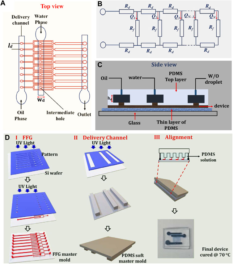
FIGURE 1. Overview of the parallelized microfluidic device design. (A) Schematic top view of the 8-FFG showing the delivery channels for the CP, DP, and outlet. (B) Theoretical frameworks for the hydraulic resistances in the ladder design for the droplet generators with a parallel arrangement. The horizontal lines with Rd represent the delivery channels, while the vertical lines attached to the horizontal lines represent the FFGs with Rg. The flow rates (Q1, Q2 …. QN) of each device are uniform such that QN = N (Rd/Rg) for N FFGs. (C) Side view of the droplet generator. (D) Step-by-step procedure of the device fabrication process using a combination of photolithography and soft lithography.
We calculate the fluidic resistance for the circular geometry (Rv) using the following equation:
where L is the length, and d is the diameter of the channel. As shown in Supplementary Table S1, both geometries had the same fluidic resistance ratio (0.0038). The designs were then exported to .STL format and transferred to the 3D printing software, GrabCAD Print (Stratasys, United States). Subsequently, both structures were printed using an Obje30 polyjet printer (Stratasys, United States) with VeroClear resin and supporting materials (Stratasys, United States), and this process took about 30 min. To remove the supporting materials, the two printed devices were sonicated in a beaker containing a mixture of sodium hydroxide beads and sodium metasilicate anhydrous (Sigma-Aldrich, United States). Both geometries were further exposed to ultraviolet (UV) light for 1 h to harden and prepare them for use (Supplementary Figure S1).
Microfluidic device fabrication
We followed the same procedure that was used to fabricate 3D monolithic elastomer devices (MEDs) aimed at solving issues with the alignment and stacking of FFG devices in our previous study (Jeong et al., 2015). This approach enables robust fabrication by employing a hard silicon master for the FFG and a soft Polydimethylsiloxane (PDMS) master for the distribution layer. The whole fabrication process consists of both photolithography and soft lithography and is divided into three stages (Figure 1D). Our devices were fabricated by following the standard procedure of the manufacturer (Kayaku Microchem). For the fluidic layer, a negative tone photoresist SU8-3,050 (Nippon Kayaku, Japan) was first spin-coated on top of an Si wafer. Thereafter, baking was performed at 95°C for more than 20 min. The photomask containing the FFG pattern was UV-exposed on the Si wafer located in the bottom layer using a mask aligner (PROWIN E100, South Korea) (Figure 1D; step I). For the intermediate holes, a negative photoresist was spin-coated on the first SU-8 layer. Subsequently, the pattern containing the intermediate holes was aligned and UV-exposed on the FFG, forming a multi-height design. The multi-height patterns were then baked at 95°C for 12 h, and the development process was performed. The mold was placed in a glass beaker containing a SU-8 developer (AZ 1500 thinner, Merck, United States) and rinsed with isopropyl alcohol (IPA) and deionized (DI) water simultaneously.
A similar procedure to step I was performed to produce the soft PDMS master. To produce the soft master, a solution of a PDMS prepolymer and a cross-linker mixed in a 10:0.5 ratio was poured onto the SU-8 pattern and cured overnight at 70°C (Figure 1D, step II). In the last stage (Figure 1D, step III), the soft PDMS master was aligned on the FFG microchannels, both of which contained the PDMS solution, and they were cured at 70°C for 12 h. To create the final microfluidic device, a thick PDMS layer was bonded to the distribution layer using a plasma cleaner (model PDC-002, Harrick Plasma, United States) for 10 min. Similar to the distribution layers, the fluidic layer was plasma-bonded to a thin layer of PDMS or glass substrate and subsequently cured overnight. In all cases, the silicon master molds were silanized using tridecafluoro-1,1,2,2-tetrahydrooctyl-1-trichlorosilane.
Scale-up design
We introduced a versatile technique by employing the PolyJet 3D printer (Objet30, Stratasys) to fabricate structures in order to increase the number of FFG devices and ultimately enhance the production rate of emulsion droplets. Two different delivery channels with rectangular and circular geometries were fabricated using a flowchart design. Both geometries were designed in accordance with the fluidic resistance requirement for rectangular and circular channels (Supplementary Figure S1). The printed devices had one inlet, one main body, and four exits that connected the CP, DP, and outlet channels of each device (Supplementary Figures S1A,B). This configuration suggests four devices can be conveniently attached to the four exists, increasing the total number of FFGs from 8 to 32.
Computational fluid dynamics simulation
We employed the commercially available simulation software ANSYS Fluent 2022 R1 (ANSYS, United States) to investigate fluid distribution patterns in the delivery and distribution channels in our device. Briefly, the models for the delivery channels and printed devices were designed using AutoDesk Inventor 2022 (Autodesk, United States). The output files were then exported in igs format and meshed in the ANSYS environment. Supplementary Figure S2A depicts a typical example of a meshed object. For fluid dynamics, water was selected as the working fluid with a density of ƞ = 9,998.2 kg/m3 and a viscosity of µ = 0.001003 kg/ms. The principal laws and mathematical framework for the fluid analysis are provided in the supplementary information. The meshed structure was then subjected to some sets of boundary conditions for the inlet, wall, and outlet ports in a fluent solver. Since the fluids of interest are oil and water, we used the incompressible Newtonian fluid laws under the laminar regime. The principal laws governing two nonnewtonian fluids are the incompressible Navier-Stokes equation (Eq. 1) and the continuity equation (Eq. 2).
Supplementary Table S1 contains the definitions for the set of parameters used in both equations. We chose water as the fluid for CFD analysis.
Materials and experimental set-up
Each injection port of the delivery channels was connected to a syringe pump via polyethylene tubes. The CP consisted of a mixture of hexadecane (Sigma-Aldrich, United States) and 2 wt% of ABIL EM-90 (Evonik- Personal Care, United States), whereas the DP was DI water. The syringe that contained the oil phase was first infused into the device until all channels were filled. After 1 min, DI water was introduced, resulting in the generation of W/O droplets that were collected at the outlet channels. Real-time observation of droplet generation was conducted using an inverted microscope (Nikon Eclipse Ti2, United States). The produced droplet was captured using the NIS-Elements software integrated with the optical microscope. Finally, the droplet diameter was analyzed and measured using the ImageJ software.
Results and discussion
Simulation results
Ladder networks are the most preferred in the parallelization scale-up technique because they have features for generating highly monodisperse droplets. Regardless of the number of FFGs, the condition in Eq. 1 must be satisfied to generate these droplets. An important criterion is to ensure that both the CP and DP fluids are uniformly delivered to the droplet generators via the intermediate holes. Thus, we conduct a 3D simulation analysis on the delivery channels (Figure 2). We investigate the condition for uniformly supplying fluids to each FFG since the transition between dripping and jetting regimes is highly sensitive to flow rates.
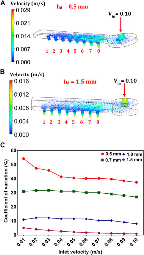
FIGURE 2. Numerical analysis of fluid flow in the delivery channels. The 3D simulation data at heights of (A) 0.5 mm and (B) 1.5 mm. The fluid enters through the inlet, and the velocity gradient observed at port outlets 1–8 provides information about the distribution variation and fluid uniformity. (C) Graph of the coefficient of variation and different hd. The dotted line implies that CV = 5%.
We consider a rectangular distribution channel with dimensions of 20.3 mm × 1.6 mm × 0.5 mm (ld ×wd ×hd) as a prototype design. To investigate the effect of height variations on the fluid distribution pattern, we made the ld and wd of the prototype design constant and varied hd to 0.7 mm, 1.0 mm, and 1.5 mm. We set the flow regime in the CFD environment to laminar and chose water as the preferred fluid. The 3D simulation of these channels provides insights into the hydrodynamic behaviour (in this case, velocity distribution) of the delivery channels. The fluid (i.e., water) passes through the inlet located at the top of the distribution channel and passes through the void space of the channels to the droplet generators (Figures 2A,B; Supplementary Figures S2B,C).
First, we vary the inlet velocity (Vin) from 0.01 to 0.10 m/s and analyse the velocity gradient at the eight exit ports. When Vin is 0.1 m/s, we observe high irregularities in the velocity distribution of the prototype design (Figure 2A). However, the device with hd = 1.5 mm exhibits a well-distributed and uniform flow pattern (Figure 2B). Generally, the degree of nonuniformity of the velocity gradient at the exit holes decreases as the Vin values increased. The high intensity at the inlet (Vin) decreases drastically as it spread through the channel void. We also observe that the outlet velocity (Vo), which is considerably lower than Vin, varying from one port to another (Figures 2A,B). Interestingly, the Vo of the device with hd = 1.5 mm was discovered to be more uniform (CV < 5%) than other channel configurations (Figure 2C). Although all the varied dimensions of the delivery channels satisfy the condition in Eq. 1, our simulation result further confirms its shortcoming. It is worth noting that the fluid variation in the exit holes was at its lowest level when hd = 1.5 mm (CV = 0.84%–4.86%). There is mainly a pressure drop between the inlet and outlet of the delivery channels as the fluid travelled through the void. The pressure loss in the exit ports increases significantly as hd increases from 0.5 to 1.5 mm. Therefore, the fluid velocity in each outlet port is expected to have similar values (i.e., uniform) with respect to changes in the channel geometry. In hydrodynamics, flow maldistribution in microchannels is highly unpredictable, which is a typical nature of the laminar flow. Thus, our findings provide optimal delivery channel dimensions for distributing fluids uniformly into parallelized channels. The integration of CFD in our study helps minimize frequent fabrication errors and experimental failures (Lashkaripour et al., 2019).
Droplet generation in the 8-FFG device
To validate the simulation results, we fabricate four sets of devices with the same height variations (0.5–1.5 mm) that is used in the CFD analysis. Both photolithography and soft lithography techniques are used to evaluate the capability of each device to produce uniform droplets. For this purpose, the flow rates of the DP (Qd) and CP (Qc) are set at 2.5 ml/h and 4 ml/h, respectively. Figure 3 shows the monodispersity of each device in terms of CV. The W/O droplets in our device are produced in the dripping regime at each FFG (Figure 3A). In contrast to a single FFG, parallelized FFGs find it difficult to generate monodispersed droplets in the dripping mode. In the dripping regime, the droplet at the orifice breaks off owing to Rayleigh capillary instability caused by interactions between viscous forces and interfacial tension (Bardin and Lee, 2014). When the device is operated at high flow rates, the polydispersity of the droplets decreases as hd increases (Figure 3B). This result agrees well with the simulated results since it demonstrates that the nonuniformity in fluid flow decreases drastically as the fluid velocity increases (Figure 2C). Experimentally, we observe that the device with hd = 1.5 mm has low CV values (CV = 2.5%) after successive measurement (n) of 100 W/O droplets. More so, the generation rate of droplets at each junction is Based on the above results, we consider this device to be the most suitable and efficient device for uniform droplet generation in this study.
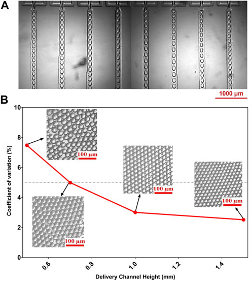
FIGURE 3. Experimental validation of the simulation result. (A) Optical image of the droplets generated in each FFG captured using an inverted microscope. (B) Graph and optical images of the W/O emulsion droplets from the outlet channels of the 8-FFG device for different hd (0.7–1.5 mm). Qc and Qd were fixed at 4 ml/h and 2.5 ml/h, respectively.
After corroborating the simulated results with the experimental results, we evaluate the role of Ca, a dimensionless parameter that plays a crucial role in generating uniform droplets. Importantly, the formation of droplets relies on the interplay between the inertial forces of the DP, viscous forces of the CP, and surface tension of the two phases (Bardin and Lee, 2014). In this study, Ca was expressed as
where
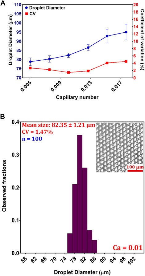
FIGURE 4. Droplet generation in the 8-FFG device: (A) variation in the droplet size as a function of Ca; (B) histogram of the W/O droplets at an optimized Ca of 0.01, with a diameter of 80.35 ± 1.21 µm and CV = 1.47% (n = 100).
Scale-up method for the four devices (32 FFGs)
FFG device stacking used to be a frequently adopted method for increasing the throughput of droplet generation, but it has been replaced by parallelization or a combination of both methods. It has been demonstrated that this technique is more effective and allows for a large number of parallelized FFG devices. First, we investigate the numerical behavior of the fluid flow pattern in the two different geometries (circular and rectangular delivery channels). This is done to ensure that all the connected devices have a uniform distribution of the CP and DP, which is an important condition for generating monodispersed droplets. To evaluate the performance of these delivery channels, the geometries are designed to have the same fluidic resistance ratio (0.0038), as presented in Supplementary Table S2. We obtain the resistance ratio for the rectangular channel by comparing the fluid resistance of the main rectangular channel (Eq. 2) to that of the exit ports (Supplementary Equation S3). Similarly, we apply Supplementary Equation S3 to calculate the resistance ratio of the circular channel (main channel and exit ports). Subsequently, a 3D simulation of the circular and rectangular flow distributors is performed, as shown in Figures 5A,B. We observe that the fluid behavior in both delivery channels was highly uniform, with a CV < 0.5%. The degree of nonuniformity in both geometries decreases as Vin increases (Figure 5C). The circular channel had a more uniformly distributed velocity gradient (0.19% < CV < 0.28%) than the rectangular channel (0.23% < CV < 0.35%). Consequently, we use both delivery channels for experimental validation. We use the 3D printing technology to fabricate ladder-like delivery channels in an experimental attempt to enhance the production rate by parallelizing four devices, each containing eight FFGs. This method allows for rapid prototyping, making it easy to adjust the distributor feature by changing the design using the software. Rectangular and circular delivery channels are fabricated in parallel orientation (Supplementary Figures S2A,B). This printed channel allowed us to conveniently connect our device to the four outlet ports of the reservoirs (4 × 8 FFGs = 32 FFGs). This concept also allows for flexibility and large-scale emulsion production using droplet generators with different designs. It is also important for enhancing uniform flow distribution in distribution geometries, regardless of their shapes or sizes (Park et al., 2018).
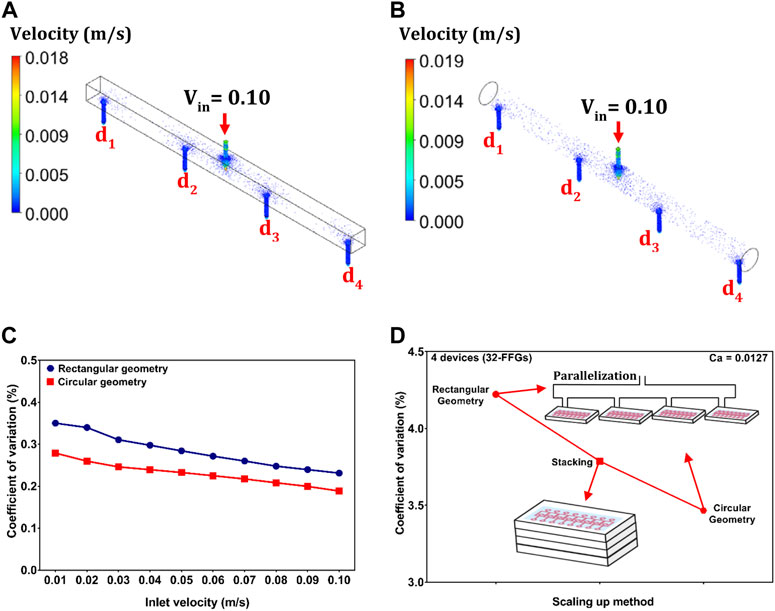
FIGURE 5. Scale-up method for enhancing droplet production via stacking and parallelization using our proposed design for the 32-FFG device. The 3D simulation data of fluid flow in the (A) rectangular and (B) circular distributors. (C) Graph of the simulated data for the circular and rectangular distributors. The velocity gradient distribution in both structures exhibits a highly uniform flow distribution (D) Experimental comparison between the stacking method and the scale-up technique involving rectangular and circular geometries as a function of the CV (n = 300). The devices for each design had a total number of 32 FFGs and were operated under the same experimental condition (Ca = 0.01).
In addition, we compare their performance of uniform distribution with that of the stacked device consisting of four layered devices (Figure 5D). The devices have a single inlet for the CP (hexadecane), DP (DI water), and outlet. A prerequisite is that all connected FFGs produce similar droplet sizes, but this is quite difficult when dealing with a large number of generators. Although the condition in Eq. 1 is affected by variation in the geometrics of FFGs or distribution channels owing to machine and fabrication errors, our fabrication method can minimize variations in channel dimension because the same molds are used for the fluidic and delivery layers. To ensure that the generated droplets are highly uniform, the experimental analysis is governed using the optimized condition for the 8-FFG device (Ca = 0.01). Figure 5D shows a comparison between the stacking method and our proposed scale-up parallelized method (involving circular and rectangular delivery channels). Although all scale-up methods produced uniform droplets (CV < 5%), the circular distributor can efficiently produce highly monodispersed W/O droplets (CV = 3.47%). These results demonstrate that the circular delivery channel can serve as the right design for enhancing the throughput of droplet generators on large scale. Additionally, the production rate can be significantly increased by easily increasing the length and the number of exit ports of the geometry. The number of measured droplets, n for the 32-FFG is 300 and the rate of production was significantly increased to
Conclusion
In summary, we conduct numerical and experimental evaluations to optimize flow behavior in the distribution channels of parallelized droplet generators. We apply CFD simulation as well as lithography and 3D printing fabrication methods to determine the most suitable operating design conditions for upscaling the production of highly monodispersed droplets. First, CFD simulation is conducted to investigate the optimal condition required to achieve uniform flow distribution in the delivery channels of droplet generators. The results confirm the shortcoming of the theoretical scaling law for droplet generators in ladder-like networks. We validate the simulation result by fabricating an 8-FFG device using photolithography and soft lithography. The experimental results agree with the simulation results owing to the generation of monodispersed droplets in the device with the highest hd (1.5 mm). Furthermore, we consider how the dimensionless parameter (Ca) affected the uniformity of the droplets in the 8-FFG device, which is an important criterion for industrial-scale production. We use 3D printing to fabricate parallel arrangements of circular and rectangular geometries to increase the production rate of a single 8-FFG device to four devices (32 FFGs). Prior to physical testing of the 32-FFG device via experimentation, we conduct a pretest analysis on the distribution reservoirs using CFD. The experimental validation confirm that the circular geometry is more effective at generating highly monodispersed droplets (CV = 3.47%) than the rectangular geometry (CV = 4.22%) and conventional stacking method (CV = 3.78%). The inclusion of CFD in our study helped minimize experimental failures by providing optimal operating conditions for a device. Thus, our proposed designs allow for easy modification and rapid production of droplet generators in order to fulfill industrial standards in just one set of experiments.
Data availability statement
The raw data supporting the conclusion of this article will be made available by the authors, without undue reservation.
Author contributions
Conceptualization: AA and H-HJ; Writing—original draft: AA; Review and editing: H-HJ. All authors equally contributed to the article and approved the submitted version.
Funding
This work was supported by the National Research Foundation of Korea (NRF) grant funded by the Korean Government (No. NRF-2020R1C1C1005505).
Conflict of interest
The authors declare that the research was conducted in the absence of any commercial or financial relationships that could be construed as a potential conflict of interest.
Publisher’s note
All claims expressed in this article are solely those of the authors and do not necessarily represent those of their affiliated organizations, or those of the publisher, the editors and the reviewers. Any product that may be evaluated in this article, or claim that may be made by its manufacturer, is not guaranteed or endorsed by the publisher.
Supplementary material
The Supplementary Material for this article can be found online at: https://www.frontiersin.org/articles/10.3389/fsens.2022.1014864/full#supplementary-material
References
Bardin, D., and Lee, A. P. (2014). Low-cost experimentation for the study of droplet microfluidics. Lab. Chip 14 (20), 3978–3986. doi:10.1039/c4lc00424h
Beebe, D. J., Mensing, G. A., and Walker, G. M. (2002). Physics and applications of microfluidics in biology. Annu. Rev. Biomed. Eng. 4 (1), 261–286. doi:10.1146/annurev.bioeng.4.112601.125916
Bhatti, M. M., Marin, M., Zeeshan, A., and Abdelsalam, S. I. (2020). Editorial: Recent trends in computational fluid dynamics. Front. Phys. 8, 593111. doi:10.3389/fphy.2020.593111
Han, T., Zhang, L., Xu, H., and Xuan, J. (2017). Factory-on-chip: Modularised microfluidic reactors for continuous mass production of functional materials. Chem. Eng. J. 326, 765–773. doi:10.1016/j.cej.2017.06.028
Han, W., Chen, X., Wu, Z., and Zheng, Y. (2019). Three-dimensional numerical simulation of droplet formation in a microfluidic flow-focusing device. J. Braz. Soc. Mech. Sci. Eng. 41 (6), 1–10. doi:10.1007/s40430-019-1767-y
Hernández-Cid, D., Pérez-González, V., Gallo-Villanueva, R., González-Valdez, J., and Mata-Gómez, M. (2020). Modeling droplet formation in microfluidic flow-focusing devices using the two-phases level set method. Mater. Today Proc. 48, 30–40. doi:10.1016/j.matpr.2020.09.417
Jeong, H.-H., Issadore, D., and Lee, D. (2016). Recent developments in scale-up of microfluidic emulsion generation via parallelization. Korean J. Chem. Eng. 33 (6), 1757–1766. doi:10.1007/s11814-016-0041-6
Jeong, H.-H., Yelleswarapu, V. R., Yadavali, S., Issadore, D., and Lee, D. (2015). Kilo-scale droplet generation in three-dimensional monolithic elastomer device (3D MED). Lab. Chip 15 (23), 4387–4392. doi:10.1039/c5lc01025j
Lashkaripour, A., Rodriguez, C., Ortiz, L., and Densmore, D. (2019). Performance tuning of microfluidic flow-focusing droplet generators. Lab. Chip 19 (6), 1041–1053. doi:10.1039/c8lc01253a
Liu, Y., and Jiang, X. (2017). Why microfluidics? Merits and trends in chemical synthesis. Lab. Chip 17 (23), 3960–3978. doi:10.1039/c7lc00627f
Malekjani, N., and Jafari, S. M. (2018). Simulation of food drying processes by Computational Fluid Dynamics (CFD); recent advances and approaches. Trends Food Sci. Technol. 78, 206–223. doi:10.1016/j.tifs.2018.06.006
Neethirajan, S., Kobayashi, I., Nakajima, M., Wu, D., Nandagopal, S., and Lin, F. (2011). Microfluidics for food, agriculture and biosystems industries. Lab. Chip 11 (9), 1574–1586. doi:10.1039/c0lc00230e
Nielsen, J. B., Hanson, R. L., Almughamsi, H. M., Pang, C., Fish, T. R., and Woolley, A. T. (2019). Microfluidics: Innovations in materials and their fabrication and functionalization. Anal. Chem. 92 (1), 150–168. doi:10.1021/acs.analchem.9b04986
Park, Y.-J., Yu, T., Yim, S.-J., You, D., and Kim, D.-P. (2018). A 3D-printed flow distributor with uniform flow rate control for multi-stacked microfluidic systems. Lab. Chip 18 (8), 1250–1258. doi:10.1039/c8lc00004b
Rahimi, M., Khorrami, A. S., and Rezai, P. (2019). Effect of device geometry on droplet size in co-axial flow-focusing microfluidic droplet generation devices. Colloids Surfaces A Physicochem. Eng. Aspects 570, 510–517. doi:10.1016/j.colsurfa.2019.03.067
Romanowsky, M. B., Abate, A. R., Rotem, A., Holtze, C., and Weitz, D. A. (2012). High throughput production of single core double emulsions in a parallelized microfluidic device. Lab. Chip 12 (4), 802–807. doi:10.1039/c2lc21033a
Sartipzadeh, O., Naghib, S. M., Seyfoori, A., Rahmanian, M., and Fateminia, F. S. (2020). Controllable size and form of droplets in microfluidic-assisted devices: Effects of channel geometry and fluid velocity on droplet size. Mater. Sci. Eng. C 109, 110606. doi:10.1016/j.msec.2019.110606
Seemann, R., Brinkmann, M., Pfohl, T., and Herminghaus, S. (2011). Droplet based microfluidics. Rep. Prog. Phys. 75 (1), 016601. doi:10.1088/0034-4885/75/1/016601
Sohrabi, S., Moraveji, M. K., and Keshavarz Moraveji, M. (2020). Droplet microfluidics: Fundamentals and its advanced applications. RSC Adv. 10 (46), 27560–27574. doi:10.1039/d0ra04566g
Sontti, S. G., and Atta, A. (2019). Numerical insights on controlled droplet formation in a microfluidic flow-focusing device. Ind. Eng. Chem. Res. 59 (9), 3702–3716. doi:10.1021/acs.iecr.9b02137
Tottori, N., and Nisisako, T. (2018). High-throughput production of satellite-free droplets through a parallelized microfluidic deterministic lateral displacement device. Sensors Actuators B Chem. 260, 918–926. doi:10.1016/j.snb.2018.01.112
Whitesides, G. M. (2006). The origins and the future of microfluidics. Nature 442 (7101), 368–373. doi:10.1038/nature05058
Wu, J., Yadavali, S., Issadore, D. A., and Lee, D. (2022). Ultrahigh throughput on‐chip synthesis of microgels with tunable mechanical properties. Adv. Mat. Technol. 7, 2101160. doi:10.1002/admt.202101160
Wu, J., Yadavali, S., Lee, D., and Issadore, D. A. (2021). Scaling up the throughput of microfluidic droplet-based materials synthesis: A review of recent progress and outlook. Appl. Phys. Rev. 8 (3), 031304. doi:10.1063/5.0049897
Yadavali, S., Jeong, H.-H., Lee, D., and Issadore, D. (2018). Silicon and glass very large scale microfluidic droplet integration for terascale generation of polymer microparticles. Nat. Commun. 9 (1), 1222–1229. doi:10.1038/s41467-018-03515-2
Yi, H., Lu, S., Wu, J., Wang, Y., and Luo, G. (2022). Parallelized microfluidic droplet generators with improved ladder–tree distributors for production of monodisperse γ-Al2O3 microspheres. Particuology 62, 47–54. doi:10.1016/j.partic.2021.08.002
Keywords: simulation, photolithography, soft lithography, 3D printing, parallelization, droplet microfluidics
Citation: Aladese AD and Jeong H-H (2022) Numerical and experimental investigations of uniform fluid distribution for droplet formation in parallelized microfluidics. Front. Sens. 3:1014864. doi: 10.3389/fsens.2022.1014864
Received: 09 August 2022; Accepted: 07 October 2022;
Published: 21 October 2022.
Edited by:
Chang-Hyung Choi, Daegu Haany University, South KoreaReviewed by:
Jae Bem You, Kyungpook National University, South KoreaHyomin Lee, Pohang University of Science and Technology, South Korea
Copyright © 2022 Aladese and Jeong. This is an open-access article distributed under the terms of the Creative Commons Attribution License (CC BY). The use, distribution or reproduction in other forums is permitted, provided the original author(s) and the copyright owner(s) are credited and that the original publication in this journal is cited, in accordance with accepted academic practice. No use, distribution or reproduction is permitted which does not comply with these terms.
*Correspondence: Heon-Ho Jeong, amVvbmdoaDI5QGpudS5hYy5rcg==