 M. Amin Azimi
 John C. Matthews
 Asal Bagherpour
 Alhossin Alsadi
 Shaurav Alam
- Louisiana Tech University, Ruston, LA, United States
Many utility owners in the United States are actively searching for new and innovative rehabilitation techniques to help them regain control and repair large tracts of their networks; moreover, traditional open cut replacement is too costly and slow to keep up with demand. Many trenchless techniques such as Spray-In-Place Pipe (SIPP) lining have been adopted by municipalities to renew their aging pipeline systems. The further development of SIPP linings could benefit the water community in the United States and around the world. SIPP lining could play a key role in controlling the future expected burden caused by the aging distribution networks. This study aimed to investigate the mechanical properties of a newly proposed reinforced spray in place pipe (SIPP) lining material that boasts structural characteristics. This material is a spray applied two component polyurethane high build coating. Three forms of sample were investigated during these tests: (1) No Fiber-Baseline (2) Rigid-with one layer of carbon fiber (3) Rigid—with two layers of carbon fiber. Three types of tests are performed: tensile, flexural, and hardness tests. This study included both experimental and Finite Element Analysis (FEA). Target mechanical properties of proposed material can be improved by using carbon fiber (CF) as reinforcement and based on the results of this study, the SIPP lining material with two layers of CF reinforcement has the highest value of 8,067 psi and 16,534 psi during the tensile and flexural test, respectively.
Introduction
Without a doubt pipeline systems, especially water distribution systems, play an essential role in our nation's infrastructure. As water infrastructure ages many authorities are concerned by the growing deficit in the repair and replacement of failing water mains (Ellison et al., 2010). The deterioration and aging of water and wastewater systems is an ever growing problem, traditional replacement is costly to perform, it becomes more costly when the disruption to everyday life are also factored. To ease these burdens many solutions have been developed to remedy aging infrastructure (Kharazmi, 2019). Many pipeline owners are now recognizing the need for rehabilitation methods to help control their systems (Selvakumar and Matthews, 2017). While rehabilitation techniques have been advancing steadily and despite large public investment few formal and quantitative evaluations are being performed to determine if the technologies are performing as they should (Allouche et al., 2014).
Spray in place pipe (SIPP) is a trenchless technology rehabilitation method for pressure and non-pressure piping systems to possibly provide a structurally independent liner able to handle the operating pressure and all applied loadings. The main purpose of SIPP lining also can be applied as a monolithic coating to the interior of a pipe that will inhibit further corrosion and eliminate water quality deterioration caused by scaling, while restoring hydraulic capacity. No rehabilitation job is the same the type of repair used is determined after assessing the level of deterioration, location, cost, and any future plans for the system (Ellison et al., 2010; Motlagh et al., 2013). There are two primary material categories used for SIPP applications: cement mortar and polymers, polymers include materials such as polyurethane, polyurea, and eopoxy (Motlagh et al., 2013).
Rehabilitation liner solutions can be categorized into four classes based on their level of performance when exposed to internal pressure. These classes are described in Table 1 (American Water Works Association, AWWA, 2001, 2021):
• Class I linings are essentially non-structural systems used primarily to protect the inner surface of the host pipe from corrosion and/or improve or maintain water quality. They are not intended to improve the structural performance of the host pipe and have a minimal ability to bridge any existing discontinuities, such as corrosion holes, cracks, or joint gaps. Hence, they usually have minimal effect on reduction or elimination of existing leakage. Their use is indicated in pipes that have internal corrosion or tuberculation but are still in structurally sound condition and where current or future leakage is not the primary design objective.
• Class II and III linings are both interactive and semi-structural systems. When installed, Class II linings shall adhere to the wall of the host pipe. Class III linings may or may not achieve reliable adhesion to the host pipe but shall be sealed to establish or maintain hydrostatic integrity. Since the pressure rating and stiffness of such a lining is < that of the host pipe, some internal pressure loads are transferred to the host pipe, leading to their classification as interactive. Class II and III linings are required to independently sustain internal pressure loads at existing or future discontinuities in the host pipe, such as corrosion pits, holes, or joint gaps.
• Class IV linings, termed fully structural or structurally independent, possess the following characteristics:
1. Long-term hoop strength, when tested independently from the host pipe, = or > the strength required to withstand the MAOP of the host pipe.
2. Short-term hoop strength, when tested independently from the host pipe, = or > the strength required to withstand all anticipated short-term loads, such as negative pressures, occasional and recurrent surge pressures, and live loads.
3. The ability to survive the full range of anticipated failure modes of the host pipe without leakage or consequential damage to the lining.
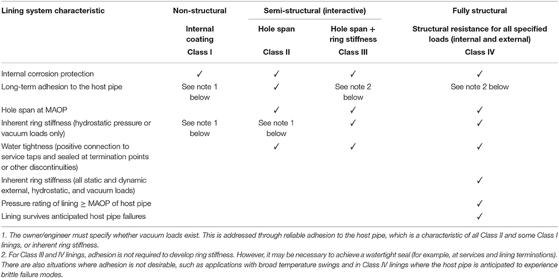
Table 1. General structural classifications objectives per AWWA M28.
Non-metallic pipe materials are used as an internal lining and standalone pipes in the oil and gas industry, constituting an emerging corrosion strategy. The non-metallic pipe materials are inherently susceptible to gradual damage due to creep, fatigue, permeation, processing defects, and installation blunder (Khalid et al., 2020). Potential failures of SIPP linings during the installation and operation along with their solutions are summarized below in Table 2 (Matthews et al., 2012).
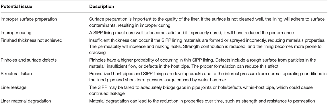
Table 2. Potential failure issues per (Matthews et al., 2012).
The objective of this study is the investigation of the mechanical properties related to Spray in Place Pipe (SIPP) lining materials with potential structural performance application; the study included three types of testing: tensile test, flexural test, and hardness test. Three different sample types were investigated in this study: (1) No Fiber-Baseline (2) Rigid-with one layer of carbon fiber (3) Rigid—with two layers of carbon fiber. The carbon fiber reinforces the SIPP system to allow it to carry higher loads than traditional SIPP material systems. This study included both lab testing and Finite Element Analysis (FEA).
This new material is a spray applied two component polyurethane, rapid curing, rigid structural lining system for high build coating. It is the wearing surface of the strong pipe Manufactured in Place Composite Pipe (MICP) system. It is designed to be robotically spray applied in sections up to 6 inches thick. The enhanced molecular design gives excellent mechanical properties with low exotherm and low shrinkage. It can be applied with or without carbon fiber reinforcement. When applied it cures rapidly for immediate return to service in pipe applications. This rigid coating is specifically designed for potable water applications. The SIPP resin properties used in this study summarized in Table 3.

Table 3. Resin properties.
Numerical Simulation
The finite element analysis (FEA) is applied for simulating the behavior of tensile and flexural samples. In this study, three-dimensional (3D) FE modeling was performed using ANSYS software. In the three-dimensional modeling the solid65 unit is used (Figure 1). The solid65 unit is an 8-node solid element. An important part of this element is processing of non-linear material properties. Plastic deformation, fracture, three orthogonal directions of cracking, and creep (if needed) are included.
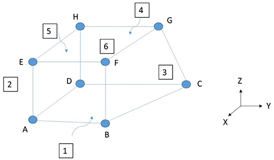
Figure 1. SOLID65 3-D concrete solid element (reproduced from ANSYS manual).
For tensile samples, one end of dog bone shape sample was considered rigid (rigid boundary condition) and tensile load was applied to the other end of the sample. Flexural samples are considered hinged (hinged boundary conditions) and only allowed to rotate in one direction at the supports while the load is applied at the top of the sample.
Experimental Study
Tensile Test
When a pipeline is subjected to an internal pressure, tensile stress can occur in the pipe. Therefore, tensile strength is a basic consideration in pipe design. This test method determines the tensile properties of unreinforced and reinforced samples using standard dumbbell-shaped test specimens. The objective of this study is to test and evaluate the innovative spray-in-place pipe (SIPP) material. This study is testing the tensile performance of the SIPP lining system on a rigid, rigid and carbon fiber (composite) layer. The carbon fiber provides reinforcement to the SIPP system to allow it to carry higher loads than traditional SIPP materials and systems.
The selection of materials dimensions and experiment procedure was followed using ASTM D683-2014 (American Society for Testing Materials, 2014). The test apparatus for conducting the long-term creep test was custom fabricated and this set-up was according to the ASTM requirements. A materials tensile strength is one of the most tested for and important properties for a material used in structural applications. The force per unit area required to break material is recorded also, it is known as the ultimate tensile strength or tensile strength at break of the material (Alzraiee et al., 2015). The dog-bone samples were mostly prepared and cut out of provided plate samples. The dimensions of the specimen such as the width and thickness were measured at three different locations. Cross sectional area was calculated from average width and thickness. The tensile test sample geometries are listed in Table 4.
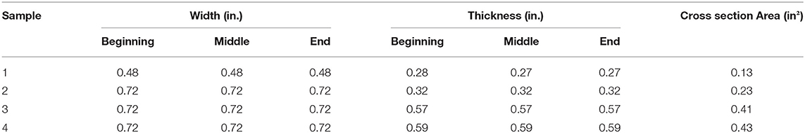
Table 4. Tensile test sample geometries.
The samples were cut using an OMAX waterjet at Louisiana Tech University as shown in Figure 2. The tensile test was conducted on four different specimen groups including ~0.33” thickness-No Fiber-Baseline, ~0.39” thickness-Rigid with Carbon Fiber, ~0.57” thickness-Rigid with Carbon Fiber, and ~0.60” thickness-Rigid with two layers of Carbon Fiber. The test was performed at a controlled temperature of 72 ± 2°F and a relative humidity of 50 ± 2%. The tensile testing machine is an ADMET universal testing machine of 10 KN maximum load. During the test, the tensile data was directly collected and analyzed by a computer connected to the testing instrument using MTestW licensed software. The setup of the experiment was performed using pneumatic powered grips (GP-16T) with 0.8-inch-wide maximum opening jaws, as shown in Figure 2 were used in the test. During tensile testing the sample is pulled until failure the force that was required to make the sample fail is a critical measurement to have. Figure 3 depicts the Finite Element Analysis (FEA) during the tensile test.
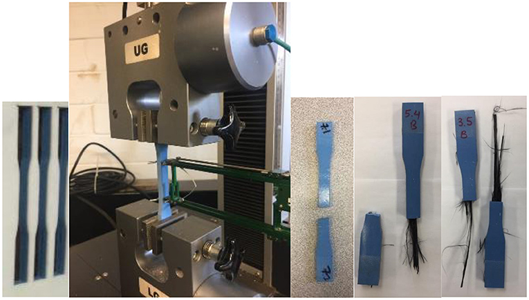
Figure 2. Tensile test sample preparation, test setup and failed samples.

Figure 3. FE tensile test.
Tensile Test Calculations
where,
A = Average initial cross-sectional area (in2),
P = Applied Force (lb).
The tensile test results for both experimental, and FEA show that the sample with two layers of carbon fiber has the highest tensile strength compared to other samples. Tensile strength has improved 26.8% with adding one layer of carbon fiber (CF) reinforcement and 48.5% by using two layers of CF reinforcements in compare with no-fiber-baseline samples. Seventeen percentage increment of tensile strength experienced in samples with two layers CF reinforcement in compare with one layer CF samples. The results also indicate that the sample with more thickness has the highest peak load compared to the same sample but with smaller thickness. Table 5 shows the result for both lab and FEA during the tensile test. The presented results are the average of five samples for each type of the sample. Figure 4 shows tensile strength and peak load results (Experimental and FE) of tensile tests for all specimens, respectively.
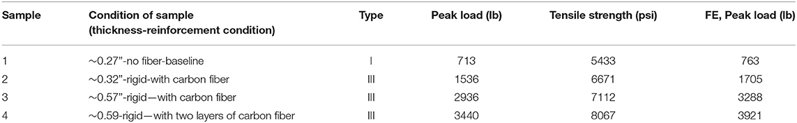
Table 5. Tensile test result.
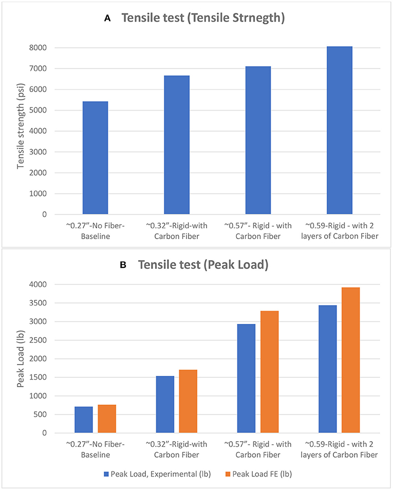
Figure 4. Tensile tests results (A) Tensile strength (psi), (B) Peak load (lb) Experimental vs. FE.
Flexural Test
Flexural loading is one of the most common types of loading experienced in practice. It is highly significant for determining the value of the bending characteristics of the liner. During the flexural test, the various deformation components are dependent on the time and load. This test method describes the method for determining flexural strength of a material using standard rectangle shaped test samples. This test method is helpful to determine the peak stress a sample can withstand while in the shape of a simplified beam (Kharazmi, 2019).
When a pipeline begins to buckle, the pipe is no longer keeps in circle shape, so the bending moment which exists in the pipe increase. Therefore, bending is one of the typical factors which could affect the creep behavior of the pipe. It is necessary to investigate the viscoelastic behavior of the pipe material under flexure (Kanchwala, 2010). The test of liner flexural properties was performed following ASTM D790-2017 (American Society for Testing Materials, 2017). Peak load and maximum flexural stress are key parameters used to determine material structural capabilities (Alzraiee et al., 2015). The flexural test samples were mostly prepared and cut out of provided plate samples. The details of the provided plate samples are listed as follow: (1) ~0.33” thickness-No Fiber-Baseline, (2) ~0.39” thickness-Rigid with Carbon Fiber, (3) ~0.57” thickness-Rigid with Carbon Fiber, and (4) ~0.60” thickness-Rigid with two layers of Carbon Fiber. The samples were cut from the retrieved liner specimen using the OMAX waterjet at Louisiana Tech University. The flexural test was conducted on different specimens. The flexural test was performed on both the neat rigid samples and rigid samples with the carbon fiber layer. The carbon fiber provides reinforcement to the SIPP lining to allow it to carry higher loads than traditional SIPP materials and systems.
The test was performed at a controlled temperature of 72 ± 2°F and a relative humidity of 50 ± 2%. The testing machine is an ADMET universal testing machine of 10 KN maximum load. During the test, the data were directly collected by a computer connected to the testing instrument using MTestW licensed software, as showing in Figure 5. Figure 6 illustrates the FEA.
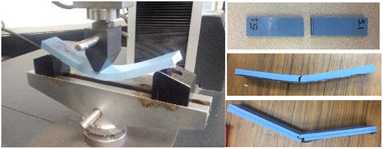
Figure 5. Flexural test.
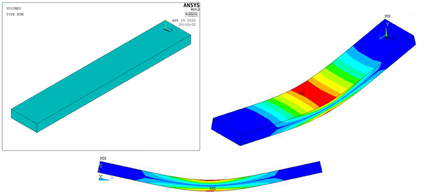
Figure 6. FE flexural test.
The results of both lab study and FEA study for the flexural test found that the sample with two-layer carbon fiber reinforcement has the highest peak stress comparing the sample with no fiber reinforcement and with one layer of carbon reinforcement as shown in Table 6. Flexural peak stress has improved 56.1% with adding one layer of carbon fiber (CF) reinforcement and 86.6% by using two layers of CF reinforcements in compare with No-fiber-baseline samples. Furthermore, 19.5% increment of flexural peak stress observed in samples with two layers CF reinforcement in compare with one layer CF samples. Similar with the results of tensile tests, presented results at Table 6 are the average of five samples for each type of the sample. Figure 7 shows flexural peak load and flexural peak stress (Experimental and FE) results of performed flexural tests for all specimens, respectively.
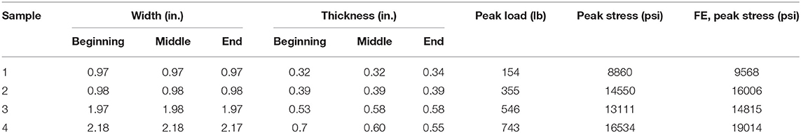
Table 6. Flexural test results.
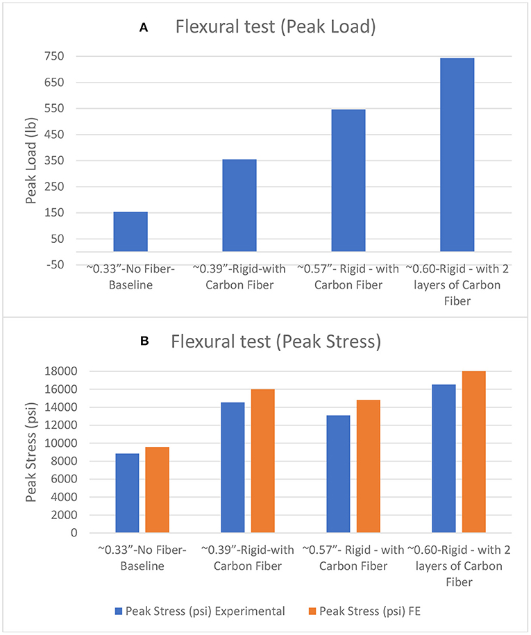
Figure 7. Flexural tests results (A) Peak load (lb), (B) Peak stress (psi) Experimental vs. FE.
Flexural Test Calculations
The maximum stress for each specimen in lb/in2 is calculated using the fallow Equation:
where, P = load (lb),
L = Span (in),
b = Width (in),
d = Depth (in).
Hardness Test
The hardness test for all samples was performed by following ASTM D2240-2015 (American Society for Testing Materials, 2015). This standard test method uses a hardness gauge, which measures the impression hardness of plastics and rubbers. We measured the hardness on two different sides, and each side was tested 10 times to get an average hardness of the material (See Figure 8).

Figure 8. Hardness test setup.
This test method uses the penetration of an indenter into the material under controlled conditions. Indentation hardness has been found to be inversely related to penetration of the selected indenter. All the samples were prepared and cut at Louisianan Tech University and been tested under standard laboratory conditions.
The results of hardness test in the lab found that the sample with one layer of carbon reinforcement (0.57”-Rigid—with Carbon Fiber) has the highest value compared to other samples as shown in Table 7. The study also found that the sample with no fiber reinforcement has the lowest value of hardness.
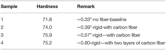
Table 7. Hardness test result.
Discussion and Conclusions
The introduced and tested material is the resin for a two-component polyurethane, rapid curing, rigid structural lining system for high build applications. This rigid coating is specifically designed for potable water applications. The objective of this study is to investigate the mechanical properties of newly introduced reinforced Spray in Place Pipe (SIPP) lining materials with fully structural performance; the study included three types of testing: tensile test, flexural test, and hardness test. There were three different material types investigated: (1) No Fiber-Baseline (2) Rigid-with one layer of Carbon Fiber and (3) Rigid—with two layers of Carbon Fiber. This study focuses on an innovative material and rehabilitation method in SIPP lining area, with the first “Fully-structural independent” performance
1. The tensile and flexural test results demonstrated the potential of fully structural application of this material specially with applying fiber reinforcement method.
2. One layer carbon fiber reinforced samples in compare with baseline samples experienced 26.8% higher tensile strength in average.
3. Double layers carbon fiber reinforced samples showed 17% and higher tensile strength in compare with one layer CF reinforced samples.
4. Max flexural stress improved 56.1% by adding one layer of CF in compare with samples with no reinforcement.
5. Double layers CF reinforced samples experienced 86.6 and 19.5% higher flexural stress in compare with No reinforcement samples and average of one-layer CF reinforced samples respectively.
6. 74.17 is the average hardness of proposed material.
Data Availability Statement
The original contributions presented in the study are included in the article/supplementary material, further inquiries can be directed to the corresponding author.
Author Contributions
All authors listed have made a substantial, direct and intellectual contribution to the work, and approved it for publication.
Conflict of Interest
The authors declare that the research was conducted in the absence of any commercial or financial relationships that could be construed as a potential conflict of interest.
Publisher's Note
All claims expressed in this article are solely those of the authors and do not necessarily represent those of their affiliated organizations, or those of the publisher, the editors and the reviewers. Any product that may be evaluated in this article, or claim that may be made by its manufacturer, is not guaranteed or endorsed by the publisher.
Acknowledgments
The authors acknowledge the financial support of SIPP Tech on this study. All data, models, and code generated or used throughout the duration of this study is proprietary or confidential in nature and may not be provided without restrictions.
References
Allouche, E., Alam, S., Simicevic, J., Sterling, R., Condit, W., Matthews, J., et al. (2014). A pilot study for retrospective evaluation of curedin- place pipe (CIPP) rehabilitation of municipal gravity sewers. Tunn. Undergr. Sp. Tech. 39, 82–93. doi: 10.1016/j.tust.2012.02.002
Alzraiee, H., Bakry, I., and Zayed, T. (2015). Destructive analysis-based testing for cured-in-place pipe. J. Perform. Constr. Facil. 29:04014095. doi: 10.1061/(ASCE)CF.1943-5509.0000567
American Society for Testing and Materials (2014). ASTM D638-14: Standard Test Method for Tensile Properties of Plastics. West Conshohocken, PA: ASTM International.
American Society for Testing and Materials (2015). ASTM D2240-15: Standard Test Method for Rubber Property: Durometer Hardness. West Conshohocken, PA: ASTM International.
American Society for Testing and Materials (2017). ASTM D790-17: Standard Test Methods for Flexural Properties of Unreinforced and Reinforced Plastics and Electrical Insulating Materials. West Conshohocken, PA: ASTM International.
American Water Works Association, AWWA. (2021). “Structural classifications of pressure pipe linings,” in Manual M28 Rehabilitation of Water Mains, 3rd Edn. Denver, CO: American Water Works Association.
Ellison, D., Sever, F., Oram, P., Lovins, W., Romer, A., Duranceau, S. J., et al. (2010). Global Review of Spray-On Structural Lining Technologies. Denver, CO: Water Research Foundation, 1–184.
Kanchwala, M. Z. (2010). Testing and design life modeling of polyurea liners for potable water pipes (Doctoral dissertation). The University of Texas at Arlington, Arlington, TX, United States.
Khalid, H. U., Ismail, M. C., and Nosbi, N. (2020). Permeation damage of polymer liner in oil and gas pipelines: a review. Polymers 12:2307. doi: 10.3390/polym12102307
Kharazmi, P. (2019). Experimental assessment of the state of the lining materials used in the rehabilitation of sewers in residential buildings. Case Stud. Constr. Mater. 11:e00291. doi: 10.1016/j.cscm.2019.e00291
Matthews, J., Condit, W., Wensick, R., Lewis, G., and Sterling, R. (2012). Performance Evaluation of Innovative Water Main Rehabilitation Spray-on Lining Product in Somerville, New Jersey. Somerville, NJ: Environmental Protection Agency.
Motlagh, S. G., Jain, A., and Najafi, M. (2013). “Comparison of spray-on linings for water pipeline renewal applications,” in Proceedings of the InPipelines 2013: Pipelines and Trenchless Construction and Renewals—A Global Perspective (Forth Worth, TX), 1113–1125. doi: 10.1061/9780784413012.104
Keywords: spray in place pipe, carbon fiber reinforcement, trenchless technology, mechanical properties, finite element analysis
Citation: Azimi MA, Matthews JC, Bagherpour A, Alsadi A, Kraft JJ, Alam S and Campos U (2021) Mechanical Properties of Novel Reinforced Spray in Place Pipe Material With Potential Fully Structural Performance Application. Front. Water 3:732845. doi: 10.3389/frwa.2021.732845
Received: 29 June 2021; Accepted: 25 August 2021;
Published: 23 September 2021.
Edited by:
Kalyan Ram Piratla, Clemson University, United StatesReviewed by:
Vinayak Kaushal, University of Texas at Arlington, United StatesMo Najafi, University of Texas at Arlington, United States
Copyright © 2021 Azimi, Matthews, Bagherpour, Alsadi, Kraft, Alam and Campos. This is an open-access article distributed under the terms of the Creative Commons Attribution License (CC BY). The use, distribution or reproduction in other forums is permitted, provided the original author(s) and the copyright owner(s) are credited and that the original publication in this journal is cited, in accordance with accepted academic practice. No use, distribution or reproduction is permitted which does not comply with these terms.
*Correspondence: M. Amin Azimi, YXppbWlAbGF0ZWNoLmVkdQ==