 Vinayak Kaushal
 Mohammad Najafi
- Center for Underground Infrastructure Research and Education (CUIRE), Department of Civil Engineering, The University of Texas at Arlington, Arlington, TX, United States
Gravity flow wastewater collection systems are comprised of sewer pipes and manholes. Failure of a manhole may have catastrophic consequences such as developing a sinkhole in the street and roadway, and at a minimum, wastewater flow will be blocked, and stream of the manhole will backup causing a sanitary sewer overflow (SSO). Improving structural conditions of a manhole is critical to minimize these types of failures. This paper considers the impact of several lining materials including cement mortar, epoxy, polyurethane, cured-in-place composites, and a multi-layer structure material on increasing the structural capabilities of deteriorated manholes. The tasks included in this research consist literature search and, preliminary laboratory and main testing of select manhole rehabilitation materials. A finite element analysis is included to complement the experiments. Several preliminary tests according to ASTM C-39 on coated concrete cylinders, and ASTM C-293 on lined concrete beams, were performed at UT Arlington's Center for Underground Infrastructure Research and Education (CUIRE) Laboratory. The test results showed significant increase in the performance of concrete samples under compression and flexure. A second round of testing was performed on 4-ft long, 24-in. diameter concrete pipe sections with 3-in. wall thickness manufactured according to ASTM C-76. These pipe sections were lined internally with the same materials as the preliminary tests, and tested according to ASTM C-497 under Three-Edge-Bearing testing. Using computer data acquisition system, strain gages and displacement extensometers, stress/strain data were measured. The results showed that tested No-Dig manhole rehabilitation materials can significantly improve structural performance of deteriorated manholes.
Introduction
Manholes are called “windows” to the sewer system as they are the most visible points in identifying the condition of underground infrastructure (Najafi, 2005). In the USA alone, the total number of manholes is estimated to be around 20 million. Of those, it is estimated that 4 million manholes are at least 50 years old and another 5 million are 30 to 50 years old (Najafi, 2005). Experience to date suggests that several million manholes in the North America have deterioration problems due to hydrogen sulfide corrosion and structural loadings (Kaushal et al., 2018, 2020).
While utilities might benefit from many options and the competition among the manufacturers, determining the most feasible and economical rehabilitation material and method often imposes a challenge for design engineers and decision makers (Table 1).
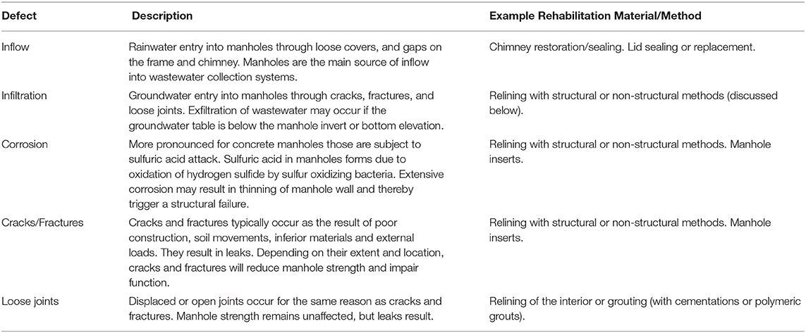
Table 1. Common Manhole Problems (Entezarmahdi, 2015).
Each of materials and methods listed in Table 1 has its pros and cons, with unknown results in enhancing structural capacity of a deteriorated manhole. The following parameters play a role in the overall structural durability and life cycle of a manhole:
• Residual strength of the manhole
• Mechanical properties of the lining material
• Adhesion between the lining and substrate (manhole component)
• Magnitude and type of loads exerted on the manhole
• Durability of manhole material against environmental effects (particularly to hydrogen sulfide induced corrosion).
Existing Conditions of Manholes
Based on 2021 ASCE Report Card for America's infrastructure, the average grade for America's wastewater system is D+ which represents “Poor” condition while the average national GPA is C- for all infrastructure sections combined. ASCE also estimates that utilities spent over $3 billion in 2019, or more than $18 per wastewater customer to replace the almost 4,700 miles of pipeline nationwide. Recently, the more prevalent use of asset management plans enables 62% of surveyed utilities to proactively manage wastewater infrastructure maintenance rather than reactively respond to pipeline and equipment failures [American Society of Civil Engineers (ASCE), 2021].
In 2019, though the annual water infrastructure capital investment gap was $81 billion, the sector has made strides to address current and future needs through resilience-related planning and innovations that produce profitable byproducts or cost savings from wastewater treatment. The reports mentioned above represent the overall condition of wastewater system in the US and state of Texas specifically. Therefore, it can be concluded that manholes, as a part of the wastewater systems require a considerable amount of investment in the next 20 years (Kaushal, 2019).
Advantages of Trenchless Rehabilitation Methods
Some advantages of using trenchless technology include minimum social costs and fewer disturbances to adjacent utilities and structures as well as minimum surface and subsurface excavations. Conventional open-cut construction methods involve the need to restore surfaces such as sidewalks, pavement, landscaping, and so on, which greatly increase the project costs (Kaushal and Najafi, 2020). In addition to the increased costs, there are social and environmental factors associated with open-cut method, i.e., its adverse impacts on the community, businesses, and commuters due to air pollution, noise and dust, safety hazards and traffic disruptions No-Dig manhole rehabilitation methods can significantly reduce the social costs (Najafi and Gokhale, 2005; Sabouni and El Naggar, 2008).
Research Need and Objectives
Inadequate structural capacity in deteriorated manholes is among the common issues that affect sewer systems and since manholes are one of the key elements of a sanitary sewer system, maintaining manholes in an acceptable condition can improve the quality of the whole system. On the other hand, deteriorated manholes with I&I issues may allow fines into the manhole and cause catastrophic consequences such as a sinkhole. Broken and separated parts of deteriorated manholes. Although, there have been a number of research studies on pipeline rehabilitation, manholes are often overlooked, though they can be the main source of inflow. On the other hand, considering the multi-billion-dollar market (at least potentially), it is not surprising that there are already numerous materials and methods available for manhole rehabilitation. This wide variety in manhole rehabilitation has its pros and cons. Therefore, there are very limited studies, but numerous options to rehabilitate manholes.
This paper considers the impact of several lining materials including cement mortar, epoxy, polyurethane, cured-in-place composites, and a multi-layer structure material on increasing the structural capabilities of deteriorated manholes. The tasks included in this research consist literature search and, preliminary laboratory and main testing of select manhole rehabilitation materials.
Literature Review
Sanitary sewer manholes are in a variety of materials and sizes. They are commonly made of brick-mortar, precast concrete block, and cast-in-place concrete. There are currently more than 20 million manholes in the united States, most of which are installed prior to 1960 (Najafi, 2005). Many the old manholes suffer from a variety of problems such as corrosion caused by sewage and gases, wearing due to traffic dynamic loads and erosion which may result in serious structural problems. Freeze and thaw, soil movements and hydrostatic loads are also among the factors that influence the deterioration of manholes. Because many manholes are located in the streets and open cut manhole rehabilitation methods may result in traffic disruptions on the streets, trenchless renewal methods can widely be used in rehabilitation of these manholes (Riahi et al., 2014; Kaushal and Najafi, 2020). Cementitious materials, polyurethane, epoxy, and cured-in-place are among the materials and methods that are used in No-Dig manhole rehabilitation and are discussed in this paper.
Manhole Inspection and Rehabilitation, ASCE Manual of Practice
Although, there is not a consensus on the capabilities of manhole rehabilitation and methods, there are a few publications that are intended to provide guidelines. A commonly recognized one was compiled by a rehabilitation committee formed under the ASCE. Entitled as Manhole Inspection and Rehabilitation, ASCE Manual of Practice (MOP) No. 92 (Hughes, 2009), provides basic information about inspection and trenchless or conventional rehabilitation of sanitary sewer manholes. A useful tool included in ASCE/MOP No. 92 is infiltration and inflow (I&I) rating based on visual inspection. This is rather a qualitative method of rating than quantitative as the latter requires costly measurements that may not be justified, especially for small projects. In addition to any active I&I at the time of manhole inspection, the ASCE/MOP No. 92 rates the severity of I&I based on physical evidence such as water marks, corrosion on the metal components (i.e. frame and cover), mineral deposits, and soil intrusion. Similar tools are suggested for a structural rating. Visual observations that are indicative of the structural condition of a manhole include corrosion, cracks/fractures, missing parts pieces, and chipping/spalling.
ASCE/MOP No. 92 provides a basic classification for manhole rehabilitation materials and methods. This classification is comprised of chemical grouting, coating systems, structural linings, corrosion protection, and frame/cover/chimney rehabilitation.
Another tool provided in the ASCE/MOP No. 92 is a present worth analysis for each manhole rehabilitation method based on their market price and expected life cycle. Present worth analysis provided in the manual assumes structural rehabilitation will provide as long as a service life (50 years) as that of a new manhole.
Overall, ASCE/MOP No. 92 is a concise and basic manual that is intended to be an educational tool for manhole rehabilitation. It is useful in terms of learning manhole components, common defects and rehabilitation methods/materials, and the approximate cost of each rehabilitation method.
National Association of Sewer Service Companies (NASSCO)
A more comprehensive guidance on manhole rehabilitation was recently compiled by the National Association of Sewer Service Companies (NASSCO) as part of the organization's Inspector Training and Certification Program (ITCP) for manholes. The NASSCO ITCP program is geared toward educating the field crew (i.e., engineers, technicians, etc.), thereby certifying them as manhole inspectors. NASSCO ITCP provides a thorough review of the available manhole rehabilitation materials and methods in addition to guidelines on manhole inspection, quality assurance/control practices, and contracting for manhole rehabilitation projects (Kaushal, 2019). NASSCO guidelines do not provide an analysis on the structural capabilities of the materials and methods used for manhole rehabilitation; as such, this project could help enhance NASSCO's training program with the manhole rehabilitation material classification. Additionally, NASSCO ITCP does not include a thorough Decision Support System that factors in manhole, soil, groundwater, traffic, and surrounding environment of a manhole. This study and NASSCO ITCP essentially complement each other they could provide a complete set of tools for manhole inspection, condition assessment, decision making, rehabilitation, and testing for quality assurance and quality control.
Automotive System for Selecting Wastewater and Water Rehabilitation Material (TTC)
In a recent study, Mathews and Allouche (2012) developed an automated decision support system for assessing the suitability of trenchless technologies as decisions related to the rehabilitation of wastewater and water infrastructure as they are becoming increasingly more complicated with respect to the number and complexity of technologies in the marketplace. Established methods, such as cured-in-place pipe (CIPP), are constantly evolving, and new techniques continue to be developed in North America and around the globe.
To address the need, the Trenchless Technology Center (TTC), in collaboration with the National Utility Contractors Association (NUCA), Australian Society of Trenchless Technology (ASTT), and NASSCO developed an interactive software for the evaluation of more than 70 technologies that can be employed in the installation, replacement, and rehabilitation of buried water and wastewater pipes (i.e., gravity driven and pressurized). Manholes were also included in the automated decision support system (DSS), which could be accessed through a Web-portal, “the Trenchless Assessment Guide for Rehabilitation (TAG-R).”
The authors describe “TAG-R” as a practical, easy-to-use, comprehensive DSS for the rehabilitation for potable water pipes and gravity sewer pipes. Manholes that provide access to sewer and drainage pipes for maintenance and inspection are also covered. There are two tables that list 14 methods that can be used for the maintenance and restoration of manhole structures or some of their components. The three primary conditions for renewal of manholes are: General maintenance for controlling infiltration/inflow, applying a corrosion resistant barrier for wall corrosion, or renewing the manhole structural integrity.
Condition 1: If the manhole is considered structurally sound with little indication of settlement, and/or was determined to have signs of structural fatigue (e.g., minor corrosion, infiltration/inflow through precast joints, mortar joints or around the pipe connections), then only general maintenance is required, which might include chemical grouting or cementitious repair. The corrosion level of a manhole can be minimal, light wall, or heavy wall. Light wall corrosion refers to a condition where the brick mortar is deteriorated and missing, or concrete surfaces are soft and flaking in spots. Heavy wall corrosion is evident when bricks or mortar are missing in a number of areas, several inches of soft concrete exposed or sections of the wall surface are missing.
Condition 2: When the manhole is exhibiting signs of moderate structural distress [e.g., minor cracks, loss of mortar or bricks, concrete corrosion <0.5 in. (12.5 mm) in depth, or minor cross-sectional distortion <10%], but is still supporting the soil and live loads, a partially structural coating/corrosion barrier is recommended.
Condition 3: If the manhole is exhibiting signs of severe structural distress and/or collapse is imminent, a fully structural renewal is recommended. Conditions that indicate this degree of deterioration would be distortion >10% of the manhole diameter, severe corrosion exposing the reinforcement steel or large sections of the structure being collapsed or missing altogether. Brick manholes lacking structural integrity have bricks missing in a number of areas with distortion in the wall.
Renewals beyond those mentioned above include bench repairs required when the bench is cracked and/or sections are missing, no bench currently exists, or groundwater infiltrating at the bench. Invert repairs are recommended if the invert is missing or eroded, the pipe running through the invert is fractured or dislodged, or the elevation does not match the elevations of the incoming and/or outgoing pipes.
The authors do not provide an in-depth evaluation of manhole rehabilitation products and methods. Also lacking is the testing results, properties of materials, and a DSS specifically provided for No-Dig manhole rehabilitation.
Previous Research on Manhole Rehabilitation
Loading and Deformation Conditions on Precast Concrete Manhole
Sabouni conducted doctoral research on loading/deformation conditions on precast concrete manholes (2008). The Sabouni study included full scale laboratory tests on three manholes. A total of 27 tests were run for different loading conditions, i.e., point and distributed loads at different locations. The loadings were based on the truck loads specified in the Canadian Highway Bridge Code (Canadian Standards Association, 2006). In addition to the full-scale tests, the study included numerical modeling with the finite element method (FEM) with 3-D elements to simulate the experimental setup as well as other simulations that represent in-situ loads on precast concrete manholes (Najafi and Sever, 2015).
The experimental setup was built at a geotechnical testing facility at the University of Western Ontario. Three precast manholes were installed in a testing chamber that was filled with soil which was laid in the chamber in compacted layers. The depth of the manholes were 25 ft. Hydraulic jacks with 202-kip capacity were used on top of the manhole specimen to simulate truck loads for various loading conditions per the Canadian Highway Bridge Code. Strain gages were attached on throughout the manhole as well as on the steel reinforcements, where they were used (the experiments included steel reinforced and unreinforced concrete manholes). Additionally, stresses in the surrounding soil were measured using pressure cells with 102 psi capacity.
Results of Sabouni's experimental and numerical analyses suggest there is minimal, if any, tensile stress/strain along a wall of a manhole. The pattern of compressive strains is somewhat complex and dependent on load type/magnitude and depth. Hoop strains are another type of deformation that occur on a manhole wall. This is mostly a compressive strain due to lateral soil pressure and analogous to the hoop strains that are encountered in pressurized pipelines, except the stress/strain tensor is in the opposite direction. The maximum strains measured due to hoop stress was between 0.002% and 0.003%, which is significantly below the cracking strain (0.008%).
Bending moments at the base of a manhole resulted in significant tensile strains. The maximum tensile strain measured on a 4-ft diameter manhole base was 0.0018%, which is 24% of the cracking strain for concrete. Shear strains were not included in the experimental procedure. Shear forces on a manhole can be significant along non-circular wall/chimney parts and around the perimeter of the manhole on the base. Another condition of significant shear stress/strain is a lateral movement of manhole components, which could be detrimental for a liner installed on the manhole.
Sabouni study concludes that the building codes used for manhole design in North America are too conservative as most of the strains measured per the loadings, applied based on the CSA 2006, were substantially lower than cracking strains. Sabouni's work is one of its kind and it is the only full-scale test applied on buried manholes with respect to their structural properties. The findings of the Sabouni study were utilized in designing and executing the tests and computational modeling conducted as a part of this study.
The Full-Scale Laboratory Tests on Manhole Rehabilitation Materials
In a recent experimental study conducted in Germany by IKT (Institute for Underground Infrastructure, 2012), performance of a select group of manhole rehabilitation materials and methods were investigated by implementing full-scale laboratory experiments and “in-situ analysis.” The full-scale laboratory tests included 20 precast concrete manholes with an average height of 18 ft. The test manholes were connected to each other with PVC and stoneware pipes. Upon application of cementitious and polymeric coatings, the manholes were subjected to external hydrostatic loads to simulate site conditions with groundwater. Defects were formed (such as holes) on the sample manholes to represent a deteriorated manhole. Then these holes were initially sealed with cementitious and polymeric grouts and lined with cementitious and polymeric coatings/linings. The lined manholes were subjected up to 17 ft of hydrostatic pressure (external) for an extended period of time (five months). The results of the lab tests generally indicated a satisfactory performance for both cementitious and polymeric coatings. Cracking and staining were common on cement mortar linings, whereas the fundamental issue with the polymeric coatings was adhesion to the substrate. A better performance of polymeric grouts was observed in comparison with the cementitious grouts.
The second phase of the IKT study included in-situ inspection of 20 manholes that were coated with cementitious and polymeric linings that have been in service from 3 to 14 years. The 13 cementitious linings generally performed well; the fundamental issue pointed out with respect to cementitious linings was application of this type of linings without stopping infiltration into the manhole completely. This results in premature curing, thereby causing disintegration of the lining applied. The seven polymeric coatings inspected in field as a part of the IKT study underperformed with a number of defects that had formed within a fraction of design life. These defects noted on polymeric coatings inspected in field were attributed to imperfections, such as cavities, on the substrate surface (manhole wall) that resulted in a rupture of polymeric coatings over the voids.
Based on the full-scale tests and field investigations, the IKT study recommended using specific materials and methods based on the condition of the manhole to be rehabilitated, i.e., if there is significant corrosion, cementitious linings were, at least as a substrate, recommended prior to applying a polymeric coating to compensate for the lost wall thickness and provide a better bond between the lining and substrate. The study also pointed out the importance of stopping leaks and creating a completely dry surface prior to application of any type of linings. In addition, surface preparation, by abrasive blasting was recommended, where polymeric coatings are applied to provide a stronger bond between the substrate and lining. The IKT study results also suggest that a manhole coating is “as strong as its weakest link” with respect to adhesion, i.e., uniform adhesive strength is needed to prevent detachment of the lining from the substrate (manhole).
Manhole Uplift Displacement and Trench-Backfill Settlement
Tobita et al. (2012) proposed a simple method to predict the uplift displacement of a manhole and trench-backfill settlement due to liquefaction. The authors proposed that conventional equilibrium of vertical forces acting on a manhole is solely a function of such forces acting and is incapable of predicting the uplift displacement [American Society of Civil Engineers (ASCE), 2009].
The Tobita et al. method adds variables including the uplift displacement, Δf, and settlements of backfill, Δs, under the condition that the volume of an uplifted portion of a manhole is equal to a settled volume of a trench-backfill. To date, the method is verified through comparison with the results of 1-G and centrifuge model tests. To derive equations for estimation of displacement of a manhole uplift and backfill settlements attributable to liquefaction, the following assumptions are made: (1) The volume of backfill is constant before and after the uplift; i.e., the uplifted portion of a manhole is equal to the settled volume of backfill, (2) The groundwater depth in backfill is kept constant before and after the uplift because the duration of uplifting may be short enough for the groundwater to permeate into the ground above the water table and (3) Pipes attached to the manhole are neglected for simplicity.
The following considerations are provided for the analyses: (1) Consideration of trench-backfill, (2) Weight of manhole and buoyant force, (3) Frictional force between backfill and side-wall of manhole, (4) Uplifting force from liquefaction, (5) Maximum manhole uplifts and backfill settlements, (6) Effects of groundwater depth and side-wall friction, and (7) Effects of excess pore water pressure ratio.
The uplift displacement and backfill settlements are derived as a function of thickness of the non-liquefied layer above the groundwater table, unit weight of backfill, width of the trench, and excess pore water pressure ratio. This method was verified through comparison with results of a shaking table test, boiling tests, and dynamic centrifuge model tests. Overall performance of the method was found to be acceptable. A new safety factor, which takes into account the amount of manhole uplift and backfill settlement, was proposed by authors and its performance was compared with that of the conventional one in which only the excess pore water pressure ratio is considered as a variable.
Dynamic effects on the manhole's uplift behavior, which is not considered in this study, may have to be investigated in detail for better estimation of manhole uplift. The predicted amount of backfill settlement by authors might be underestimated because settlements attributable to consolidation after liquefaction are assumed to be zero for simplicity.
Rehabilitation of Polymer Concrete Manhole Rehabilitation
Another study was performed by Ahn et al. (2009) to check the feasibility of concrete polymer manhole rehabilitation through a development test of high strength polymer concrete and prepare fundamental data for design to solve the problems of an existing cement concrete manhole. The lower absorption capacity (0.39%) of polymer concrete is deemed more advantageous in installing manholes in areas with high groundwater table. Also, long working-life (63 min) of polymer concrete would be adequate for a manhole application.
A testing program was developed, which includes the following parameters: Fillers, Aggregate, Shrinkage reducing agent, Releasing agent, and Mixture proportioning. The following specific parameters were measured as a part of the testing procedure: Working-life, Workability, Ultimate mechanical strength, Modulus of elasticity, and Poisson's ratio.
Results of the Ahn et al. study indicated a specific gravity of polymer concrete as 2.30 (on average), its absorption capacity was 0.39% and its unit weight is not much different from that of cement concrete. Nevertheless, its lower absorption capacity would be more advantageous in manholes exposed to groundwater. The compressive and flexural strengths of polymer concrete were measured 18,400 psi and 3,200 psi, respectively. Such mechanical strength figures suggest polymer concrete has enough stiffness to build a new manhole with this material. The Ahn et al. study is a useful reference with respect to considering polymer concrete as an alternative manhole rehabilitation material.
Methodology
As stated previously, this research focuses on structural capabilities of No-Dig manhole rehabilitation materials. The required background information was collected through literature review. The following tests were conducted to measure the structural capabilities of the lining materials.
• Compression test per ASTM C-39 on lined concrete cylinders
• Flexural test per ASTM C-293 on lined concrete beams
• Three-edge bearing test on internally lined 24 in. diameter concrete pipe per ASTM C-497
Figure 1 outlines the process flow for the research tasks.
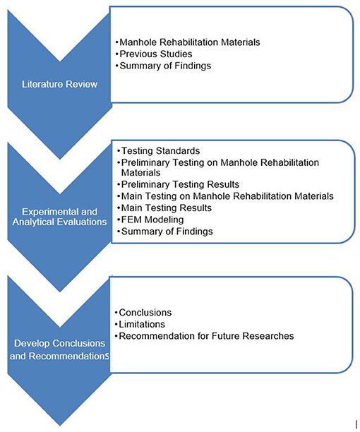
Figure 1. Research methodology flowchart.
Experimental Testing
Two types of tests were performed in this research: (1) Preliminary Tests and (2) Main Tests.
Preliminary Tests
The materials included in the preliminary tests were two epoxy liners (EPX1 and EPX2), one polyurethane (PU), one corrosion resistant cement liner (CMT), one multi structural composite lining systems with modified pleurae and foam (MULT), and one resin impregnated cured-in-place lining system (CIP). Two types of tests (compression and flexural) were conducted on the lined (representative of manhole wall-lining system) and unlined (control) specimens regarding loads and stresses on manholes. Compression and flexural tests were conducted as per ASTM C39 and ASTM C293, respectively. Forty-two concrete cylinders (4 × 8 in.) and 41 concrete beams (3 × 3 × 11 in.) samples were prepared for the preliminary tests. The design strength of concrete was approximately 5,000 psi.
The unlined (control) specimens prepared for the preliminary experiments are shown in Figure 2.

Figure 2. Unlined (control) specimens prepared for the preliminary experiments.
A total of 70 concrete specimens were sent to seven participating companies (10 each—five concrete cylinder and five beam specimens) for lining with their manhole rehabilitation product, using their standard procedure. Following instructions were given to manufacturers for lining:
1. Line the whole circumferential surface of cylinders evenly using your standard procedure.
2. Line one large surface of the beam. Smaller end surfaces need not be lined.
3. Thickness shall be minimum 100 mils (2.5 mm) for epoxy and polyurethane.
Figure 3 shows concrete cylinder (a) and beam (b) samples lined with high-build polyurethane and Figure 4 shows concrete cylinder (a) and beam (b) samples lined with cured-in-place liner.
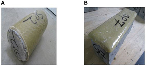
Figure 3. Concrete cylinder (A) and beam (B) samples lined with high-build polyurethane.

Figure 4. Concrete cylinder (A) and beam (B) samples lined with cured-in-place liner.
Five identical beam and cylinder specimens were lined by the manufacturer using their standard procedure (including surface prep) and tested at CUIRE by two-point bending and compressive loading until failure (Figure 5).
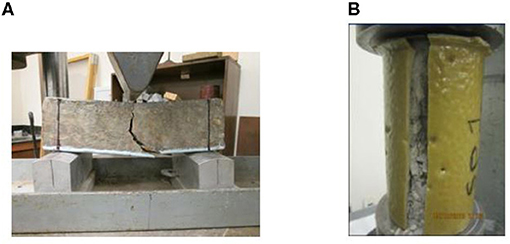
Figure 5. Beam (A) and cylindrical (B) specimens at failure while loaded for flexural and compressive strength, respectively.
Figures 6, 7 show the views of the concrete cylinder before and after compressive loading, whereas Figures 8, 9 show the concrete beam views before and after flexural loading.
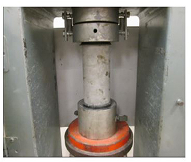
Figure 6. Unlined (control) cylinder prior to compression testing.
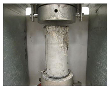
Figure 7. Unlined (control) cylinder after compression testing.
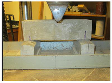
Figure 8. Unlined (control) beam prior to flexural testing.

Figure 9. Unlined (control) beam after to flexural testing.
Main Tests
The preliminary tests helped to gain an overall understanding of the capabilities of spray applied and cured-in-place linings with respect to adding strength to concrete specimens per the ASTM Standards C39 and C293. Nevertheless, two questions remained upon completion of the preliminary test:
1. How would an internally lined concrete cylinder, that is more representative of an actual manhole, behave under compressive and tensile stresses?
2. Is there a practical way to analyze the lined system under compressive strains?
To answer these questions, it was decided to use 24-inch concrete cylinders as substrates for the main tests. The concrete cylinders are standard reinforced concrete pipes manufactured to ASTM C76 and typically used for storm sewer applications. The main test samples were loaded by applying the standard Three-edge-bearing test per ASTM C497. The ASTM C497 procedure was slightly modified to install strain gages at four positions (i.e., 12:00, 3:00, 6:00, and 9:00 o'clock) to measure the tensile and compressive stresses along the internal perimeter of the host pipe. This allowed a comparison of lined specimens strains to that of unlined (bare) specimens during loading.
discussion of Results
The discussion of results is divided into two parts as follows: (1) Preliminary Test Results and (2) Main Test Results.
Preliminary Test Results
The preliminary tests results suggested that spray applied and cured-in-place linings could significantly, if not substantially, add to the ultimate flexural and compression strengths of concrete substrates. These results were at comparable thicknesses to actual manholes. The added flexural strength to the concrete substrate varied with thickness to a level that the difference in the ultimate strength was affected more by the lining thickness than the material itself for several cases. Nevertheless, the ultimate flexural strength versus liner thickness plot suggests the liner thickness does not have a significant effect on the flexural strength of the lined specimens for thicknesses >7.0 mm (275 mils).
Due to possible expansion-contraction of the lining around the concrete cylinder during compressive loading, the added ultimate strength to the concrete cylinders was more of a result of the “confining effect” of the liner on the substrate. This may as well be the case for test specimens as they were lined on the exterior under compression, which is not the case for actual manholes in the field. The stress/strain distribution over the lined cylinders were not investigated as part of the preliminary tests; and therefore, the exact behavior of the lined cylinders under the given loading condition is unknown.
Main Test Results
The results for main tests show significant increase in flexural and compression strength of concrete pipes. Like the preliminary testing, thickness of the liner and the type of liner were among the key factors that affected the structural capabilities of concrete pipes. The other factors are quality of installation, substrate preparation, weather conditions (temperature, humidity, wind, etc.), and curing time.
The results of 250-mil thickness specimens for Epoxy, Polyurethane and Multi-Structural liners show that material property has a major impact on ultimate strength of manholes with epoxy having more impact than other two materials. Although thickness is a key factor in increasing the strength, it does not necessary mean that higher thickness of the liner will result in significant increase in the failure load. Test results of the samples with 125, 250 and 500 mils of polyurethane liner illustrated that liner thickness did not increase strength as expected when the liner thickness was increased from 250 to 500 mils.
The preliminary and main test results indicated that the lining materials have significantly increased the structural capabilities of the concrete samples. For instance, epoxy lining material increased the peak load between 45 and 133 percent in main testing based on the thickness of the liner. Similarly, cementitious lining material increased the peak load between 25 and 127 percent, polyurethane between 34 and 52 percent, and cured-in-place lining materials increased the peak load by 54 percent (see Table 2).
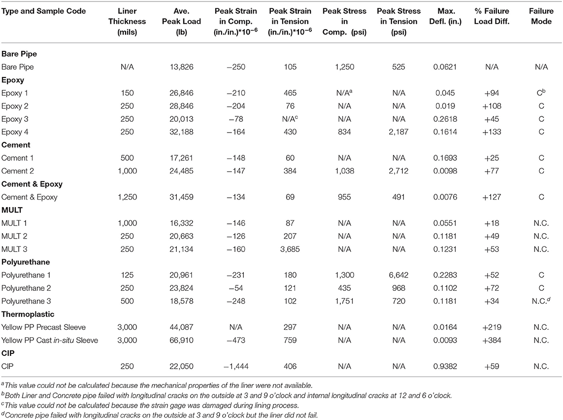
Table 2. Summary of Test Results.
Finite Element Modeling
The main test specimens were instrumented using strain gages and displacement transducers which were connected to a data acquisition system to record the readings. The test data was used to develop a Finite Element Model. The results of the FEM analysis on epoxy lining material are presented below.
Methodology
A multipurpose finite element software (ABAQUS) was used to study the structural capability of the epoxy liners. Simulations were performed on three cases: flexural beam test, pipe crushing test, and manhole structure under uniform soil and hydrostatic pressure. The experimental test results were used to calibrate the accuracy of the FEM.
FEM Results
Flexural Strength
Figure 10 shows that the failure load obtained from simulation was 2,165 lb with a deflection of 0.0019 in. which is in good agreement with the average peak load from laboratory tests on bare concrete (1,834 lb). The failure load and deflection for lined specimen were 2,922 lb and 0.0051 in., respectively.

Figure 10. Crack propagation in the bare concrete beam.
Pipe Crushing
As it is illustrated in Figure 11, the bright areas in the plastic strain contour which represent the predicted cracks match with the cracks occurred in the Three- edge-bearing tests. Pressure-deformation curves obtained from the simulations in this case are shown in Figure 12 which indicates a peak pressure of 17.8 psi at 0.021 in. deformation for bare concrete pipe.
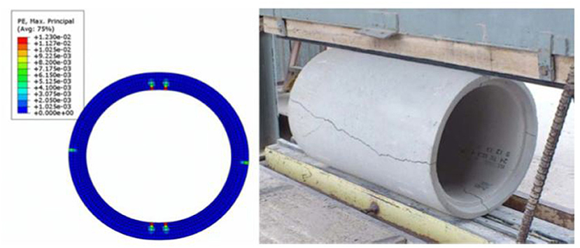
Figure 11. Crack propagation in bare concrete pipe.
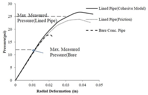
Figure 12. Pressure deformation curve of bare and lined concrete pipes.
Figure 13 illustrates that using epoxy liner with a cohesive interaction behavior increases the pressure capacity of the pipe.
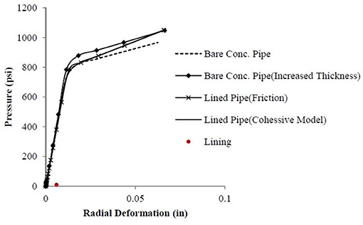
Figure 13. Pressure deformation curve for bare and lined concrete pipes under uniform pressure.
Uniform Pressure
Figure 13 presents pressure-deformation curve obtained from the lined and unlined pipe simulations under uniform peripheral pressure. The pressure shown in the plot is the concrete radial stress at the outside boundary. The simulations were performed for four models: bare concrete pipe, lined concrete pipe with friction contact, lined pipe with cohesive contact, and bare concrete pipe with increased thickness equal to the total thickness of lined concrete pipe. The curves show that bare concrete with larger thickness can carry the largest pressure as expected. However, the pipe with lining does not show increase of the pressure.
Conclusions
The conclusions of this paper can be summarized as follows:
• The preliminary and main test results proved that all the selected lining materials in this study added to the structural capacity of the specimens. Therefore, it can be concluded that No-Dig manhole rehabilitation material will add to the structural capabilities of the host manholes.
• Mechanical properties, thickness of the liner, quality of installation, substrate preparation, weather conditions and curing time are the key factors in manholes liner installation.
• Multi Structural Lining Materials like Epoxy and Glass Fiber or Modified Polyuria and Specialty Foam or CIP can address I&I issues because they do not crack when the concrete substrate cracks at failure.
• Cementitious Liner or epoxy can be used to exceed structural capacity of the manholes.
Limitations and Recommendations for Future Research
The main lining and testing were done outdoor in cold winter weather which might have slightly impacted the test results. In this research, due to resource limitations, 24 in. concrete pipes were used to simulate manholes. Long-term mechanical properties of the liners may change over time.
For future, it is recommended to conduct experiments on full size manholes with loading conditions like actual field conditions. There is also a need to perform experimental tests on concrete manhole sections and to conduct experiments to measure the long-term structural capabilities of the lining materials. Instrumented flexural and compression tests with strain gages is further suggested.
Data Availability Statement
The datasets presented in this study can be found in online repositories. The names of the repository/repositories and accession number(s) can be found below: https://rc.library.uta.edu/uta-ir/handle/10106/25096.
Author Contributions
All authors listed have made a substantial, direct and intellectual contribution to the work, and approved it for publication.
Funding
This research project was possible from a grant funding by the Water Environmental Research Foundation (WERF) as a part of USEPA's Innovation and Research for Water Infrastructure for the 21st Century program.
Conflict of Interest
The authors declare that the research was conducted in the absence of any commercial or financial relationships that could be construed as a potential conflict of interest.
Publisher's Note
All claims expressed in this article are solely those of the authors and do not necessarily represent those of their affiliated organizations, or those of the publisher, the editors and the reviewers. Any product that may be evaluated in this article, or claim that may be made by its manufacturer, is not guaranteed or endorsed by the publisher.
Acknowledgments
The content of this manuscript has been presented (in part) at the Pipelines 2014 Conference, (Entezarmahdi et al., 2014).
References
Ahn, N., Park, D. K., Lee, J., and Lee, M. K. (2009). Structural Test of Precast Polymer Concrete. J. Appl. Polym. Sci. 114, 1370–1376. doi: 10.1002/app.30731
American Society for Testing and Materials (ASTM). (2013a). ASTM C-76 Standard Specification for Reinforced Concrete Culvert, Storm Drain, and Sewer Pipe.
American Society for Testing and Materials (ASTM). (2013b). ASTM C 497 Standard Test Methods for Concrete Pipe, Manhole Sections (External Load Crushing Strength).
American Society for Testing and Materials (ASTM) (2013c). ASTM C-39 Standard Test Method for Compressive Strength of Cylindrical Concrete Specimens.
American Society for Testing and Materials (ASTM) (2013d). ASTM C-293 Standard Test Method for Flexural Strength of Concrete (Using Simple Beam with Center Point Loading).
American Society of Civil Engineers (ASCE) (2009). Manhole inspection and rehabilitation. Reston, VA: American Society of Civil Engineers.
American Society of Civil Engineers (ASCE) (2021). Score Card. Reston, VA: American Society of Civil Engineers.
Entezarmahdi, A. (2015). Testing, analysis and classification of no-dig manhole rehabilitation materials (Master's thesis). University of Texas at Arlington, TX, USA. Available online at: https://www.proquest.com/docview/1699700887?pq-origsite=gscholar&fromopenview=true
Entezarmahdi, A., Najafi, M., and Sever, V. F. (2014). Testing and Analysis of No-Dig Structural Manhole Rehabilitation Materials, in Proceedings of Pipelines 2014 Conference, ASCE (Portland, Oregon). doi: 10.1061/9780784413692.153
Hughes, J. (2009). Manhole inspection and rehabilitation, 2nd Edn. Reston, VA: ASCE. doi: 10.1061/9780784410530
Institute for Underground Infrastructure (IKT) (2012). Rehabilitation of Wastewater Manholes: Large Scale Tests and In-Situ Studies. Available at: http://www.ikt.de/down/english/2012_04.pdf (accessed January 1, 2013).
Kaushal, V. (2019). Comparison of environmental and social costs of trenchless cured-in-place pipe renewal method with open-cut pipeline replacement for sanitary sewers (Doctoral Dissertation). University of Texas at Arlington, TX, USA.
Kaushal, V., and Najafi, M. (2020). Comparative analysis of environmental and social costs of trenchless cured-in-place pipe renewal method with open-cut pipeline replacement for sanitary Sewers. J. Pipeline Syst. Eng. Pract. 11:04020037. doi: 10.1061/(ASCE)PS.1949-1204.0000480
Kaushal, V., Najafi, M., and Love, J. (2018). Qualitative investigation of microbially induced corrosion of concrete in sanitary sewer pipe and manholes, Proc. Pipelines 2018: Condition Assessment, Construction, and Rehabilitation (Reston, VA: American Society of Civil Engineers), 768–775. doi: 10.1061/9780784481653.086
Kaushal, V., Najafi, M., Love, J., and Qasim, S. R. (2020). Microbiologically induced deterioration and protection of concrete in municipal sewerage system: technical review. J. Pipeline Syst. Eng. Pract. 11:03119002. doi: 10.1061/(ASCE)PS.1949-1204.0000424
Mathews, J., and Allouche, E. (2012). Fully automated decision support system for assessing the suitability of trenchless technologies. J. Pipeline Syst. Eng. Pract. 3, 55–64. doi: 10.1061/(ASCE)PS.1949-1204.0000095
Najafi, M. (2005). Trenchless Technology: Pipeline and Utility Design, Construction, and Renewal. New York, NY: McGraw-Hill.
Najafi, M., and Gokhale, S. (2005). Trenchless Technology: Pipeline and Utility Design, Construction, and Renewal. New York, NY: McGraw-Hill.
Najafi, M., and Sever, F. (2015). Capabilities of No-Dig Manhole Rehabilitation Materials. Water Environmental Research Foundation. Available at: https://www.hightail.com/download/bXBiRFFYTkE4Q1J2Zk1UQw (accessed May, 2021)
Riahi, E., Najafi, M., and Sever, F. (2014). Evaluation of structural performance of epoxy linings for manhole rehabilitation using laboratory testing and FEM simulations, in Proceedings of Pipelines 2014, American Society of Civil Engineers (ASCE) (Reston, VA). doi: 10.1061/9780784413692.120
Sabouni, R., and El Naggar, M. H. (2008). Full scale testing of 1200 mm diameter precast concrete manhole, in Proc. Second Canadian Conference on Effective Design of Structures (Hamilton, Ontario, Canada).
Keywords: manhole, rehabilitation materials, trenchless technology, sustainability, asset management
Citation: Kaushal V, Najafi M and Entezarmahdi A (2021) Testing, Analysis and Classification of No-Dig Manhole Rehabilitation Materials. Front. Water 3:713817. doi: 10.3389/frwa.2021.713817
Received: 24 May 2021; Accepted: 28 June 2021;
Published: 23 July 2021.
Edited by:
John Matthews, Louisiana Tech University, United StatesReviewed by:
Katarzyna Pietrucha-Urbanik, Rzeszów University of Technology, PolandSumit Purohit, Pacific Northwest National Laboratory (DOE), United States
Copyright © 2021 Kaushal, Najafi and Entezarmahdi. This is an open-access article distributed under the terms of the Creative Commons Attribution License (CC BY). The use, distribution or reproduction in other forums is permitted, provided the original author(s) and the copyright owner(s) are credited and that the original publication in this journal is cited, in accordance with accepted academic practice. No use, distribution or reproduction is permitted which does not comply with these terms.
*Correspondence: Vinayak Kaushal, dmluYXlhay5rYXVzaGFsQHV0YS5lZHU=