
95% of researchers rate our articles as excellent or good
Learn more about the work of our research integrity team to safeguard the quality of each article we publish.
Find out more
ORIGINAL RESEARCH article
Front. Virtual Real. , 09 February 2022
Sec. Virtual Reality in Industry
Volume 3 - 2022 | https://doi.org/10.3389/frvir.2022.781830
This article is part of the Research Topic Digital Twin for Industry 4.0 View all 5 articles
Cobotic workstations in industrial plants involve a new kind of collaborative robots that can interact with operators. These cobots enable more flexibility and they can reduce the cycle time and the floor space of the workstation. However, cobots also introduce new safety concerns with regard to operators, and they may have an impact on the workstation ergonomics. For those reasons, introducing cobots in a workstation always require additional studies on safety and ergonomics before being applied and certified. Certification rules are often complex to understand. We present the SEEROB framework for the Safety and Ergonomics Evaluation of ROBotic workstations. The SEEROB framework simulates a physics-based digital twin of the cobotic workstation and computes a large panel of criteria used for safety and ergonomics. These criteria may be processed for the certification of the workstation. The SEEROB framework also uses extended reality technologies to display the digital twin and its associated data: users can use virtual reality headsets for the design of non-existing workstations, and mixed reality devices to better understand safety and ergonomics constraints on existing workstations. The SEEROB framework was tested on various laboratory and industrial use cases, involving different kinds of robots.
In the automotive and aeronautics industries, repetitive workstations are fully automatized with robots. These robots can work autonomously behind physical barriers. However, in some cases, the operators presence is needed to introduce more flexibility and more accuracy, to guide the robot, or to detect defaults. A close physical interaction between robots and operators is then possible. To guarantee the operators’ safety, new robots are introduced as collaborative robots (cobots). They can be intrinsically safe, meaning that embedded sensors can detect collisions and trigger safety stops, or additional extrinsic safety sensors (such as cameras or immaterial barriers) may be needed to supervise the workstation. Introducing collaborative robots inside a workstation is definitely bringing modifications on its space configuration: removing physical barriers reduces the workstation floor space (Saenz et al., 2020), while new areas are occupied by the robot or new sensors. These modifications may have an impact on the workstation ergonomics for human operators working next to the robot.
Cobotic workstations need to guarantee the operators’ safety: they must comply to specific regulations before being integrated inside industrial plants. For example, such regulations are described in the ISO/TS 15 066 technical specifications (ISO, 2016). These regulations define different scenarios of human-robot collaboration and different safety criteria for each scenario. In some cases, a protective separation distance is required between operators and robots. In other cases, the force and pressure deployed by the robot’s end-effector must not exceed a specific norm, depending on the impacted body region.
Regulations like the ISO/TS 15 066 are often difficult to understand, interpret and apply on the workstation (Saenz et al., 2021). They are also complex to graphically represent in the work environment. In most cases, complying to regulations can be achieved by reducing the robot’s speed, but this can lead to very conservative situations with a lack of performance (Svarný et al., 2020). Sometimes, more precise criteria than those used in regulations, such as computations on the robot’s effective mass (Kirschner et al., 2021), may be used to both guarantee the workstation safety and keep an acceptable level of performance. Moreover, regulations often consider the worst case scenario and define static safety distances, while dynamic safety areas could be defined depending on the robot’s configuration and speed.
Digital twins are an interesting tool to help engineers display their cobotic workstations and perform simulations for safety and ergonomics assessments. A digital twin is a 3D virtual representation of an existing workstation. This workstation can contain multiple objects, such as machines, conveyors, robots, sensors, automated vehicules, and can involve multiple operators. By extension, digital twins are also often used to simulate workstations that do not exist yet. Digital twins can be linked to their real counterpart in real-time, or they can be autonomous and use standalone simulations.
By animating a 3D representation of the workstation, digital twins enable the simulation of multiple configurations and can compute additional data such as safety and ergonomics scores. Virtual representations of the workstation can also display safety criteria in an intuitive way, such as safety distances or dangerous portions of a trajectory. Digital twins have already been used by specific frameworks for robotics studies, for example to assess physical human-robot assembly systems (Malik and Brem, 2021) or to assist in the workspace configuration (Wojtynek and Wrede, 2020). Machine learning can also be used to enhance digital twins and to prototype different robot control strategies (Dröder et al., 2018). Kousi et al. (2019) also present a close approach to the one described in this paper, by using digital twins and real-time sensors data to adapt the layout of robot workcells and modify robot behaviours.
Beyond simulating virtual workstations, machines and sensors, digital twins may also be used for ergonomics studies, by evaluating the operators movements and postures through digital human models, as proposed by Castro et al. (2019). Digital human models may be animated by hand or by motion capture. Ergonomics assessments provide different kinds of outputs depending on the motion tracking hardware and the evaluation scores. Eichler et al. (2021) provide an interesting review of different hardware requirements and ergonomics assessment methods. Most basic postural assessment methods may be found in many software tools, such as the ErgoToolkit proposed by Alexopoulos et al. (2013).
Extended reality technologies enable to go a step further. Virtual reality headsets can be used by engineers and operators to be directly immersed inside the digital twin: operators tasks can be simulated and users get a better understanding of distances and speeds. Mixed reality devices can be used on real workstations to augment the real robots and machines with additional data: robot trajectories, robot speed, sensor safety areas. This can help engineers to better configure their workstation by both keeping their real robot and trajectories and adding virtual information.
Virtual reality technologies have already been used by specific frameworks to assess workstation ergonomics (Pavlou et al., 2021) or to prototype human-robot collaboration scenarios (Matsas et al., 2018). However, in these frameworks, digital twins are purely virtual and they are not linked to a real workstation. Comparisons between virtual and physical workstations were performed by Weistroffer et al. (2014) to assess human-robot copresence acceptability, but there was no real-time communication between the digital twin and the real environment. The benefits of mixed reality technologies was shown by Filipenko et al. (2020) with a preliminary design tool for industrial robotics applications.
In this paper, we present the SEEROB framework, used for the simulation of digital twins and the Safety and Ergonomics Evaluation of ROBotic workstations. Digital twins are modelled and animated thanks to emulated and real data coming from robot controllers and automata. The SEEROB framework uses the XDE physics engine (Merlhiot, 2007) to process the real data of the workstation, animate a physics-based digital twin and compute additional data for safety and ergonomics. Finally, the SEEROB framework uses extended reality technologies to display the digital twin inside virtual and mixed reality environments, and motion capture can be used to simulate the operator’s tasks and perform ergonomics analyses.
To our knowledge, the SEEROB framework contributions rely on many ideas that are not used together in other frameworks:
• It can access data from real controllers and automata in real-time, making the safety assessments more relevant and closer to the real situation;
• It uses a precise physics engine to simulate a physics-based digital twin and compute precise safety and ergonomics criteria;
• It uses extended reality technologies to make the digital twin more interactive: users are directly immersed inside the virtual or mixed environment and can better understand safety and ergonomics issues;
• It uses digital human models and motion capture technology to perform precise ergonomics assessments directly inside the digital twin.
The SEEROB framework is composed of three main modules:
• A physics engine to process real-time data and animate a physics-based digital twin;
• A safety toolbox to compute safety criteria;
• An ergonomics toolbox to capture and evaluate operators’ postures.
The global architecture of the physics-based digital twin is described in Figure 1. It consists of a digital twin model, a digital twin state, a physics engine and a graphics engine.
In the SEEROB framework, digital twins are described by two sets of parameters: a digital twin model representing the geometry and physics parameters of the workstation, and a digital twin state representing dynamic parameters at a specific time. The digital twin model can be seen as a static representation of the workstation, including 3D geometry and parameters such as kinematic axes, kinematic centers, masses, inertia, damping and friction of the workstation elements. The 3D geometry is used both for display and physics purposes (to compute collisions). The digital twin state consists of the necessary parameters to dynamically animate the digital twin, such as joints articular positions and velocities. The digital twin state must be accessed in a continuous way to provide a correct dynamic animation.
The digital twin model and state are directly handled by the XDE physics engine (eXtended Dynamics Engine (Merlhiot, 2007)). This physics engine is focused on rigid body dynamics and can simulate a large panel of mechanical systems, such as robot arms, mobile robots, virtual humans (considered as humanoid robots) and industrial machines. The digital twin model is used as a first set of inputs to configure the XDE physics components: kinematic and dynamic data are used for rigid body parameters, while geometric data is used for rigid body collisions. The digital twin state is used as a second set of inputs during the simulation to dynamically control the physics components. The XDE physics engine is able to compute precise distances and collisions between components of the simulation (for example between a robot and an operator), based on the 3D geometry of the components. The XDE physics engine enables to animate the digital twin in a physics-based way, rather than just a graphical way, and provides additional data on robot parameters (speed, energy, efforts), safety and ergonomics.
For display purposes, the SEEROB framework uses the Unity3D1 platform. The digital twin model is first imported inside Unity3D to display the 3D geometry. Then, this 3D representation is animated in real time based on the simulation state provided by the XDE physics engine: the positions of physics components, collisions states and additional physics parameters are sent in real-time thanks to a server–client architecture. Unity3D also enables to display the digital twin inside Extended Reality environments.
Each module of the global architecture is explained with more details in the following sections.
The SEEROB framework requires a digital twin model as a first set of inputs for the digital twin simulation. This model consists of geometric data (3D representation of the workstation) and physics metadata (kinematic and dynamic properties of objects).
Geometric data is first used by Unity3D for display purposes, while the XDE physics engine uses this data for physics purposes and collisions computation. Geometric data must be adapted for each purpose: 3D display must be fluid and keep small visual details, while collision detection must be fast, robust and precise. Therefore, the graphics engine and the physics engine do not necessarily share the same level of details of the 3D models.
Geometric data is usually contained inside a CAD file, extracted from a CAD software (for example Delmia or SolidWorks). It can be extracted into multiple file formats: .3dxml,.sdlprt,.step … Some formats are already tesselated (3D meshes are represented as multiple small triangles), while other formats keep the internal representation of the meshes as curves and surfaces. These CAD files must be correctly parsed in order to import the 3D representation of the workstation inside any third-party application. However, the multiplicity of file formats makes it difficult to develop and maintain such universal parsing tools.
Some solutions exist on the market to import a large panel of CAD formats, such as PiXYZ2 or CAD Exchanger3 which both develop plugins for the Unity3D platform. Both plugins are used inside the SEEROB framework. Different parameters are used to generate adapted 3D representations for Unity3D and for the XDE physics engine. Both Unity3D and XDE use tesselated 3D models, with a bigger level of details for physics purposes.
Geometric data only gives information on the 3D shapes of the elements of the workstation, but it does not provide information on their mechanical properties. Such data, often called metadata, consists of the physics parameters (kinematic axes, kinematic centers, angular limits, masses, inertia, damping, friction) of the different elements of the workstation. These parameters define the dynamic model of a robot or a machine.
Physics properties of a digital twin are crucial since they guarantee the fidelity of the simulated workstation with regard to the real one. Analyses and decisions performed on the digital twin can be incorrect if the model is not well configured. Getting precise physics properties (masses, inertia) is difficult and not always possible, since this data may not be available or willingly given by machine constructors. That is why some studies are specifically focused on the identification of such parameters (Jubien et al., 2014) (Stürz et al., 2017) (Tika et al., 2020).
Physics properties can be extracted directly from the original CAD file (if the data is available and exportable), or it can be described inside a separated file in a specific format. The URDF (Unified Robot Description Format) file format is one example of metadata description, especially used in robotics.
In the SEEROB framework, when possible, we use the dynamic models given by constructors or extracted from research studies. The SEEROB framework can import URDF files but it also handles other metadata formats (proprietary formats). When importing metadata, it is important to retrieve which parts in the 3D scene need to be updated. In the SEEROB framework, this process is performed by referencing the parts by their full names in the scene graph (the names unicity has to be guaranteed).
When no text description is available, physics properties can be entered manually inside the SEEROB framework. If the precise physics properties are not known, the XDE physics engine can be used to provide an estimation of the center of mass and inertia of specific elements, based on their mass and assuming a uniform density. Work is still on-going to retrieve kinematic axes and centers automatically from the 3D shapes of the elements.
Once the digital twin is fully described with its geometric data and physics metadata, the SEEROB framework needs a second set of inputs to represent the digital twin state at a specific time. This state consists of the robots joints positions and velocities, the tools Cartesian positions or the sensors values.
In the SEEROB framework, the digital twin state can be accessed off-line (data is stored inside files or comes from simulation software) or in real-time (data is streamed from the real workstation). This data is eventually used to animate the digital twin, by moving the 3D objects in space or changing the representation of sensors.
Robot trajectories are often programmed off-line inside a simulation software before being integrated onto the real robot. Each robot constructor has its own simulation software (Kuka.Sim, URSim, Fanuc Roboguide … ). Non-constructor robot simulators also exist to support a wide range of robots, such as Delmia (Dassault Systemes), RoboDK or Gazebo. Simulation software can often export robot trajectories into readable files. For example, Delmia can export robot trajectories into Excel files containing the robot joints’ positions and velocities and the end-effector’s Cartesian position and velocity. These files are the easiest way to process data (no physical setup is required) but they do not provide a real-time synchronization with the real workstation.
In the SEEROB framework, we provide the possibility to read robot trajectories from Excel files. Data from the files are parsed and stored inside the framework to be replayed during the simulation. Data from a specific robot arm can be used to control any robot arm with the same number of degrees of freedom (see Section 2.1.4). The SEEROB framework can also access robot trajectories from simulation software when communication is possible. This is the case with URSim using the RTDE interface (see Section 2.1.3.2).
The issue with most robot simulators is that they emulate the robot controllers behaviour. The controller models may contain uncertainties which can lead to differences with the real controllers behaviour: small trajectory errors, or different strategies to prevent singularities. To counter this issue, the Realistic Robot Simulation interface RRS-1 (Bernhardt et al., 1994) and the Virtual Robot Controller interface RRS-2 VRC (Bernhardt et al., 2000) were introduced as a standard for industrial robot controllers. However, to our knowledge, this standard is not used in the whole robotics community and it does not support every robot model.
In the SEEROB safety certification approach, reading trajectories or emulated data is performed only as a preliminary analysis, since these robot trajectories may differ from the real robot controllers behaviour. Real-time communication with robot controllers is the preferred option to access more relevant data.
The SEEROB framework provides several ways to communicate with native robot controllers (see Figure 2). Specific developments have been integrated to use the Fast Robot Interface (FRI) for Kuka robots, the Real-Time Data Exchange (RTDE) interface for UR robots and the Doosan Robot Framework Library (DRFL) for Doosan robots. For each robot interface, the robot controller data (joints articular positions and velocities) is accessed in real time through an ethernet connection and is provided to the XDE physics engine on the connected computer. Robot controller data is sent at around 100 Hz depending on the robot controller.
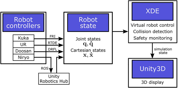
FIGURE 2. Architecture focus on robots digital twins. Robots state is accessed from robot controllers in real time and sent to the XDE physics engine to process in the physics simulation, before sending the simulation state to Unity3D for display.
The SEEROB framework also provides real-time communication with ROS (Robot Operating System), which is a well-known generic framework intending to mutualise developments on robot controllers and providing a rich toolset for the development, simulation and visualization of robotics applications. Communication with ROS is achieved by using the Unity Robotics Hub4 plugin. This Unity3D plugin enables to send Cartesian targets from Unity3D to the connected robot controller, while receiving the robot’s joint state (articular positions and velocities) from the controller in real-time. In the SEEROB framework, the robot state is finally sent again from Unity3D to the XDE physics engine.
Not all robot constructors are compatible with ROS and robot drivers are often developed by the community, which can lead to uncertainties in the safety certification results. Some robots are natively compatible with ROS, such as Doosan robots for industrial applications and Niryo5 robots for education.
The SEEROB framework provides real-time communication with Programmable Logic Controllers (PLC), or automatons. Automatons can provide data from all the machines of the workstation (robot joints states, sensors states, conveyors states); they can also receive commands to trigger some actions.
Communication with PLCs can be achieved in several ways. Some PLCs provide web services which can be accessed through web requests. Other standard frameworks are also emerging, based on OPC-UA communication and AutomationML description. In the SEEROB framework, it is necessary to maintain an explicit dictionary of the PLC variables used in the digital twin, in order to know how PLC variables (names and values) are used in the simulation components. This process may be complex if a huge number of variables is used. That is why work is on-going to find usable standards, for example with Companion Specifications (OPCFoundation, 2019). Communication with PLCs is still an on-going work inside the SEEROB framework.
In some cases, it is not possible to get continuous access to the digital twin state: it is only possible to get waypoints at specific instants of the trajectory. These waypoints may be defined in the joint space (an angle and velocity for each robot joint) or in the task space (the Cartesian position and velocity of the end-effector).
In the SEEROB framework, waypoints may be imported from metadata files or be added manually. These waypoints can be displayed alongside the 3D model of the digital twin. In such simulations, more intelligence is needed to compute continuous states based on the waypoints data: this is performed by path planning tools included inside the XDE physics engine.
In the SEEROB framework, we use the XDE physics engine (eXtended Dynamics Engine (Merlhiot, 2007)) to animate the digital twin, based on the dynamic data provided by the workstation (off-line data or real-time data). XDE is focused on rigid body dynamics, with the simulation of kinematic chains such as robot arms or virtual humans (considered as humanoid robots), the simulation of body friction and collisions, the computation of precise contact points on complex geometric data, the implementation of proportional-derivative controllers to move bodies in the joint or task spaces, and the simulation of sensors (lasers, intrusion areas).
Using a physics engine is necessary both for animating the digital twin and for monitoring additional data (see Figure 3), such as velocities, torques, forces, energies and collisions. Moreover, the digital twin may contain virtual objects that do not exist in the real workstation, such as a gripper or a virtual environment: these objects must be taken into account in the physics simulation since they can impact the simulation state (masses, efforts, collisions).

FIGURE 3. Principle of a physics-based digital twin. Red objects are purely virtual and do not exist in the real workstation, but they can be taken into account in the physics engine computations. The outputs of the physics engine (joints positions, velocities and torques) may differ from the real workstation.
The XDE physics engine is able to compute collisions (contact points) and minimal distances between non-convex objects with a high precision in real time, contrary to other physics engines which can only handle convex objects. This is crucial for the monitoring of the digital twin, for example to compute safety criteria with precision and fidelity. The XDE physics engine is also able to emulate robot controllers, based on Cartesian and articular waypoints. These controllers do not guarantee the fidelity with real controllers but they can propose basic robot movements when no data is available from the real workstation.
In the SEEROB framework, the digital twin state is used as a desired state by the XDE physics engine. Based on this data, forces are computed and applied on the digital twin to make it move and achieve the desired state. These forces are computed using proportional-derivative controllers. Gains of the controllers are automatically tuned based on the objects’ masses and inertia.
Usually, the desired state of the digital twin is represented in the joint space: robots are described by their joint configuration (joints positions and velocities), and torques are applied to each joint to achieve a desired joint configuration. In some cases, the desired state of the digital twin may be represented in the task space: robots are described by the Cartesian position of their end-effector. In such cases, multiple solutions may exist to actuate joints to achieve a desired Cartesian position (depending on the robot’s redundancy), and the fidelity to the real workstation is not guaranteed.
The XDE physics engine is a C++ library made of several plugins (rigid body dynamics, human simulation, safety monitoring). It runs at around 100 Hz depending on the scene complexity. It communicates with external applications (robot controllers, graphics engines) thanks to a server–client architecture based on the Web Application Messaging Protocol (WAMP) and MessagePack (msgpack) serialization format. Robot data is sent at around 100 Hz from the robot controllers to XDE. Motion capture data is sent between 30 and 90 Hz (depending on the tracking devices) from the tracking system to XDE. There can be data frame losses but XDE always considers the most recent data frames to ensure real-time. Delays can occur but they are essentially related to the computer performance.
The SEEROB framework uses the Unity3D platform to display the digital twin. The digital twin model is first imported using CAD plugins such as PiXYZ or CAD Exchanger. Then, a (soft) real-time communication is established between the XDE physics engine and the Unity3D platform: the physics engine sends the positions of bodies to be displayed, the sensors states and additional information, while Unity3D sends back information from the user (for example keyboard events and user position data).
With such an architecture, the update loops of the physics engine and the graphics engine can be decorrelated: the graphics engine is not impacted by the physics engine performance (if computations are slow) and can run at full framerate with the minimum latency. This is important when using virtual reality headsets for which at least 90 Hz is required to prevent motion sickness.
The SEEROB framework benefits from the Unity3D support of a large panel of Virtual Reality headsets, essentially working with the SteamVR plugin (HTC Vive, Oculus Rift, Windows Mixed Reality headsets). The SEEROB framework also uses the CloudXR streaming functionalities from Nvidia6 to support wireless headsets such as Oculus Quest.
With these functionalities, the digital twin can be easily displayed inside a virtual reality environment: the user is immersed inside the digital twin and can interact with it, as if playing the role of an operator or a supervisor. Displaying the digital twin inside a virtual reality environment, rather than on a simple desktop setup, helps the users have a good representation of the workstation, in terms of distances, speeds and accessibility. This tool can be used by engineers to help them in the design of new workstations.
The SEEROB framework also benefits from the Unity3D support of a large panel of Mixed Reality devices, such as Hololens (Microsoft), or HTC Vive headsets using a Zed mini camera (StereoLabs7). Mixed reality devices may be used to enhance existing workstations with additional data coming from the digital twin: for example to display safety distances, safety speeds, kinetic energies, or even to add a virtual dangerous tool at the robot’s end-effector. The mixed reality environment can help operators and engineers understand what is happening on the workstation and focus on specific areas or trajectories that could be dangerous, without any actual physical threat. Operators can place virtual safety sensors next to the real robot and observe the impact on the digital twin.
The SEEROB framework uses a specific calibration process to correctly position the digital twin with regard to the real workstation. The main method uses two HTC Vive Trackers: one located on the Mixed Reality device (either a HTC Vive headset enhanced with a Zed mini camera, or a tracked Zed camera), and one located at a known position in the real workstation. Hololens calibration is performed manually or by using a QR code. In the future, the SEEROB framework intends to support other mixed reality devices, such as Lynx headsets8.
The role of a digital twin is not simply to model and animate a virtual twin of a physical workstation, but to enhance it with additional data. For example, data from the digital twin can be used to compute cycle times, to foresee possible failures and defaults, to perform safety analyses, to assess the workstation ergonomics … In the following section, we focus on the safety analyses for cobotic workstations. We first present the norms imposed by the ISO/TS 15 066 regulation. Then, we present the safety toolbox implemented in the SEEROB framework to better understand and comply to these norms.
Most cobotic workstations, involving one or several cobots in physical interaction with humans, must be certified based on specific norms, such as the ISO/TS 15 066. The ISO/TS 15 066 defines four different collaboration scenarios with different safety strategies (Marvel and Norcross, 2017) (Scalera et al., 2020): hand-guiding, safety-rated monitored stop, speed and separation monitoring (SSM), and power and force limiting (PFL). In the two last cases (SSM and PFL), the workstation must guarantee specific constraints on minimum distance, maximum speed or maximum force to be certified.
The Speed and Separation Monitoring strategy imposes a protective separation distance (PSD) between a cobot and a human. This distance may be seen as a (dynamic) hull around the robot representing the necessary area for the robot to come to a complete stop. At all times, the human should not enter the area defined by the PSD; said differently, the minimum distance between the human and the robot should not exceed the PSD.
The protective separation distance Sp is composed of four main contributions (see Eq. 1): the distance Sr covered by the robot during the system reaction time, the distance Ss covered by the robot between the reaction time and the effective stop, the distance Sh covered by the human during the whole stopping process, and a set ξ of tolerances and uncertainties. The PSD may change dynamically in time (depending on the robot and human states) or may be fixed as the worst case scenario. One way to reduce the PSD is to adapt and reduce the robot’s speed (Zanchettin et al., 2016) (Joseph et al., 2020).
In most models, the PSD is computed as an approximation depending on multiple robot and human parameters (Marvel and Norcross, 2017) (Glogowski et al., 2019) (Scalera et al., 2020) (Lacevic et al., 2020). An upper approximation of the PSD is often given by Eq. 2, where vr is the current effector’s speed, Tr and Ts are the reaction and stopping times of the robot and vh is the current human’s speed (usually estimated at 1.6 m/s).
The SSM safety strategy is essentially used for workstations in which contacts between the robot and the human are only permitted when the robot’s speed is zero. However, collisions between a robot and a human may be considered safe even if the velocity is non-zero: human body limbs can resist collision forces without being hurt. The Power and Force Limiting (PFL) strategy defines limits in the forces and powers deployed by the robot’s end-effector. These limits depend on the body limbs to consider and the impact situation (transient or quasi-static). This approach requires specific knowledge on human injuries which can be accessed through databases (Haddadin et al., 2012) (Mansfeld et al., 2018).
A collision between a body part and a robot link may be modelled as a linear spring-damper system with a stiffness k depending on the impacted body part (Vemula et al., 2018) (Svarný et al., 2020) (Ferraguti et al., 2020). A simple relationship may then be established between the impact force F and the transferred energy E (Lachner et al., 2021) (see Equation 3), involving the robot’s effective mass. Force limits given by the ISO/TS 15 066 can then be transcribed into velocity and energy limits, which can be easier to interpret or compute.
In the SEEROB framework, a panel of various safety criteria were implemented to better understand robot configurations and parameters, to highlight potential risks and to comply to safety regulations:
• Swept volumes;
• Manipulability;
• Velocity and kinetic energy;
• Force polytope;
• Effective mass;
• Minimum distances;
• Safety areas.
These criteria are represented in Figure 4. They are directly computed by the XDE physics engine in real time. These criteria can be displayed and combined together (see Figure 5) to perform a safety analysis and monitor the risks for different body parts in different impact situations.
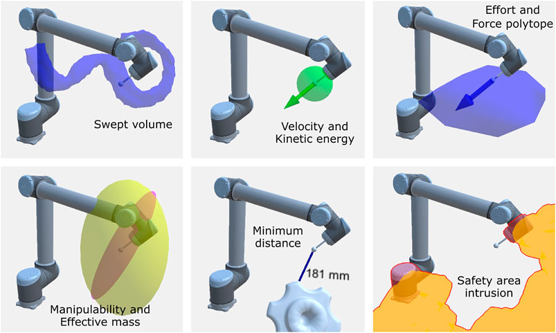
FIGURE 4. Samples of safety criteria computed by the SEEROB framework. In the bottom left picture, the manipulability ellipsoid is represented in yellow and the effective mass in purple. In the bottom right picture, the robot links intruding in the yellow safety area are highlighted in red.
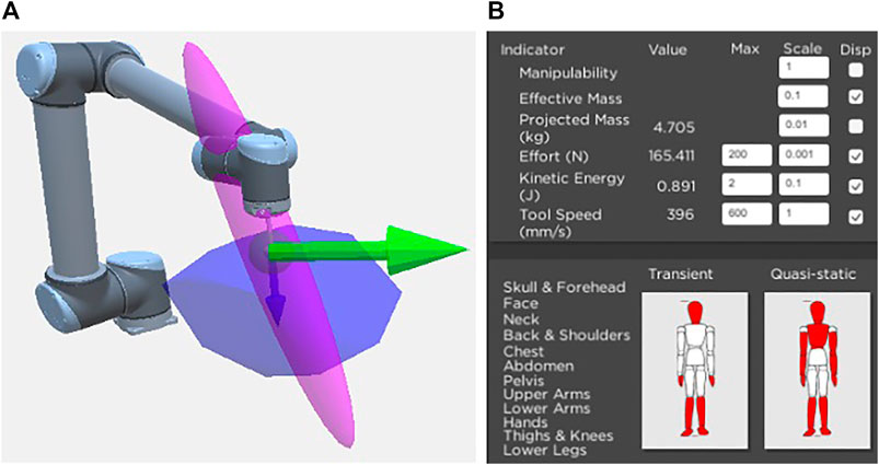
FIGURE 5. Display of multiple safety criteria in the 3D scene (A) and in a 2D interface (B), showing the risks for different body parts for transient and quasi-static impacts.
In the following subsections, we consider a robot arm with n degrees of freedom, a joint configuration
For convenience, we focus on the robot’s end-effector: any point of interest on the effector can be considered by introducing the adjoint transformation. The method and computations are also valid for other robot links than the end-effector, by removing the contributions of the corresponding last joints.
Swept volumes represent the robot’s working area. They can define the whole reachable area of the robot (based on its kinematics and joint limits) or the area swept by the robot during a specific part of a trajectory. In the SEEROB framework, the XDE physics engine computes swept volumes thanks to a voxel representation of the digital twin. The size of the voxels can be modified: smaller voxels will provide a detailed swept volume but will need more computation time. In the virtual environment, swept volumes are represented by a 3D shape.
Manipulability describes how easily a robot’s end-effector can move in different directions (Lynch and Park, 2017). It is strongly related to the robot’s singularities for which the robot can be unstable. In the SEEROB framework, manipulability is described by an ellipsoid whose axes are defined by the eigenvectors of
In the SEEROB framework, the XDE physics engine is used to compute the Cartesian velocity
In the SEEROB framework, robot velocities are used to compute a protective separation area around the robot for the SSM safety strategy. Robot velocities and energy are also compared to the norms imposed by the PFL safety strategy for transient impacts.
In the SEEROB framework, the robot’s end-effector force is compared to the norms imposed by the PFL safety strategy for quasi-static impacts. However, the end-effector force is not always known with precision, or because the robot lacks force sensors. The robot’s end-effector force
When the robot’s current joint torques are not known, the robot’s maximum torques can be used to compute a set of possible maximum forces deployed by the end-effector, often called the force polytope (Chiacchio et al., 1997) (Skuric et al., 2020) or the actuation wrench polytope (Orsolino et al., 2018). For a robot with n degrees of freedom, the force polytope contains 2n vertices.
In the SEEROB framework, the force polytope is represented by a convex hull around the robot’s end-effector. This hull can be compared to a 3D sphere (whose radius is given by the norms of the PFL safety strategy) to define if the configuration is safe or not.
The effective mass is an interesting criteria representing the perceived mass in certain directions. It is involved in the impact model between a human and a robot to connect effort values to energy values.
In the SEEROB framework, the effective mass matrix
The projected mass
The XDE physics engine is able to compute the current minimum distance between two sets of objects, for example between a robot and an operator or between a robot and the environment. This distance may be compared to the protective separation distance defined by the SSM safety strategy.
Minimum distances are computed based on the objects meshes: XDE provides the 3D points on the objects surfaces that verify the minimum distance. Minimum distances are computed in real-time and can consider non-convex objects. This approach is much more precise than in other frameworks where objects centroids are often considered. In the virtual environment, minimum distances are represented by a line joining the 3D points realizing the minimum distance.
In the SEEROB framework, the XDE physics engine is used to compute the intrusion of objects inside safety areas. These safety areas can represent a hull around the robot, defined for example by a swept volume or a protective separation distance. They can also be seen as static areas supervised by safety cameras or lidars. Safety areas can be configured manually or be extracted from robot controllers when possible.
XDE can handle non-convex areas and detect intrusions in real-time. In the virtual environment, safety areas are represented by semi-transparent 3D objects and they change color when an intrusion is detected. Safety areas only give visual feedback to operators; sound feedback or haptic feedback (through a smart watch for example) could be added but they were not studied in the context of this paper.
By simulating the real workstation and computing various safety criteria, the digital twin enables to focus on specific parts of a trajectory that could be dangerous. However, when performing safety analyses, it is also important to take the operator’s behaviour and tasks into account. In basic simulation software, this is performed by placing static manikins in the virtual scene and providing them with basic animations. This strategy is easy to use but it cannot simulate all possible behaviours and it lacks flexibility.
The SEEROB framework uses extended reality to address this issue. By immersing the operator inside the digital twin with a virtual reality headset, a virtual manikin is animated in the digital twin in real time. The operator can simulate any tasks and movements, even unpredicted ones, and the virtual manikin data (position, velocity) is used to compute more precise and more relevant safety criteria: minimum distance to the robot, relative speed. This approach is not possible with basic simulation software and is one of the key benefits of using extended reality technologies for digital twin simulation.
Sometimes, modifications on workstations are applied to improve the safety, but they can also trigger bad postures and modifications on the operator’s tasks. That is why it is important to assess the workstation ergonomics.
The ergonomics toolbox of the SEEROB framework is composed of three modules (see Figure 6:
• Digital human models;
• Motion capture;
• Ergonomics evaluation.
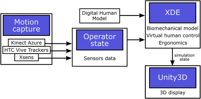
FIGURE 6. Architecture focus on operators digital twins. Operators state is accessed from motion capture sensors in real time and sent to the XDE physics engine to process in the physics simulation, before sending the simulation state to Unity3D for display.
Digital human models (DHM) are the virtual representation of operators inside simulations. They are represented by a given morphology and a set of bones linked together by joints. They can be static or animated by hand or by motion capture. In our framework, digital human models are an additional element of digital twin models (see Figure 1).
In the SEEROB framework, the digital human model contains a set of 21 bones linked together by joints (see Figure 7), for a total of 53 degrees of freedom (47 joint axes + 6 degrees of freedom for the waist). The digital human model is configured by a set of lengths and masses. These parameters can be given manually or they can be automatically generated based on a total height and a total mass, by using datasets and proportionality constants (Drillis et al., 1964) (Zatsiorsky and Seluyanov, 1979). A Kinect Azure camera can also be used to scan and estimate the user’s morphology.
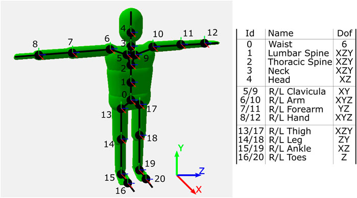
FIGURE 7. The digital human model used in the SEEROB framework. It contains 21 bones and a total of 53 degrees of freedom (dofs).
The digital human exterior skin is defined by 3D primitives (capsules and dilated planes) whose dimensions depend on the limbs lengths and masses. These 3D primitives are also used by the physics engine to compute collisions and distances with the 3D environment.
In the same way than robot controllers and automata provide data from the real workstation, motion capture sensors can provide data on the operators positions and postures. This data may be seen as additional parameters of the digital twin state (see Figure 1). Sensors may be placed on the operator’s body, with optical systems (such as HTC Vive Trackers tracked by lighthouses) or inertial measurement units (such as Xsens sensors). Some optical systems do not require the placement of sensors on the operator’s body, such as the Kinect Azure from Microsoft, a single depth-camera giving access to the whole skeleton joints positions.
Motion capture devices provide data on the operator’s state. This data is then processed to animate a digital human model of the operator. Depending on the number of sensors and the type of data (positions, rotations), it can be difficult to control the human model. One solution is to animate the digital human model through basic inverse kinematics algorithms. In the SEEROB framework, we rather use a physics-based approach: we use the XDE physics engine to process the motion capture sensors data as a desired state for a proportional-derivative controller. The digital human model is animated by this controller and can interact with its environment.
The SEEROB framework can handle different kinds of motion capture data. It is compatible with Xsens Awinda suits, containing 17 inertial measurement units. It can use the data from HTC Vive Trackers, with a minimum of five sensors placed on the waist, the legs and the arms. It can also process the data coming from a Kinect Azure to track the operator’s posture without any sensor. All devices may also be used together to get hybrid configurations: for example, using a Kinect Azure for the global posture and IMUs to track the wrists and the head with more precision.
The accuracy of the different motion tracking systems was not measured, since this topic is already handled by serious studies in the literature (Albert et al., 2020). The accuracy of the system using HTC Vive Trackers is estimated around 1 cm, while the accuracy of the system using a Kinect Azure is estimated around 2 cm (depending on the depth), with a better accuracy for the upper body than for the lower body.
When the digital human model is animated based on the operator’s movements, the posture can be analyzed to assess the workstation ergonomics. This is usually performed thanks to ergonomics rules: postures are given specific scores depending on their constraints, a high score meaning a non-ergonomic posture. The Rapid Upper Limb Assessment RULA (McAtamney and Corlett, 1993) is a standard tool used to compute scores for the upper body. Other rules have been implemented to be more complete than RULA, such as REBA (Hignett and McAtamney, 2000) or EAWS (Schaub et al., 2012). Usually, industrial partners have their own ergonomics rules.
In the SEEROB framework, we use RULA scores and we also adapt scores from industrial partners. The digital human model is colored based on the ergonomics scores: green means a low-constraint posture, while red means a high-constraint posture. The process used to control the digital human model and analyze the posture is shown in Figure 8.

FIGURE 8. Motion capture sensors (6 HTC Vive Trackers for the lower torso, upper torso, forearms and legs, and 5 Xsens sensors for the hands, feet and head) are used to capture the user’s posture (A). A digital human model is controlled to mimic the user’s position and posture (B). An ergonomics assessment is performed based on the digital human posture (C). The real setup and the virtual human are rendered together thanks to a Zed camera (StereoLabs) tracked with a HTC Vive Tracker.
At the end of a motion capture session, the SEEROB framework can export various data into readable files: sensors raw data (positions, rotations), the digital human limbs positions and angulations and the ergonomics scores.
The SEEROB framework was tested on several use cases, both in laboratories and with industrial partners. For confidentiality reasons, the content of each industrial use case cannot be described in details but the whole method is illustrated. Each use case describes a different step in the design of cobotic workcells, with virtual, mixed and real environments.
The SEEROB framework was tested in two experimental real environments. The first one (see Figure 9) involves a Kuka iiwa robot working on a motor together with an operator. The second one (see Figure 10) involves a Universal Robot UR10 and an operator on an assembly line. Both digital twins were modelled thanks to the CAD models of the workstations. They are animated in real-time by accessing the robot states through the FRI interface for the Kuka iiwa robot and the RTDE interface for the UR10 robot.
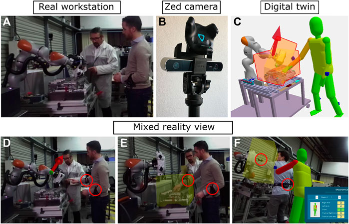
FIGURE 9. An industrial use case involving one Kuka iiwa robot. The real workstation (A) and the digital twin (C) are superimposed thanks to a Zed camera (B) to show robot velocities (D), safety areas (E) and ergonomics scores (F). Motion capture sensors (HTC Vive Trackers) are circled in red.
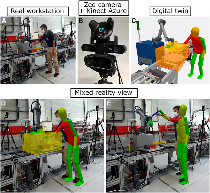
FIGURE 10. A laboratory use case involving one UR10 robot. The real workstation (A) and the digital twin (C) are superimposed thanks to a Zed camera (B) to show the effector velocity, energy, safety areas, minimum distance to the operator and ergonomics scores (D, and E). The operator’s posture is tracked thanks to a Kinect Azure camera fixed together with the Zed camera; the offset between the real operator and the virtual manikin is due to inaccuracies in the motion tracking system and the cameras calibration.
The digital twins are displayed and superimposed over the real workstations thanks to a Zed camera tracked by a HTC Vive Tracker. The calibration between the digital twin and the real setup is performed by placing a HTC Vive Tracker at a specific location in space, for example next to the robot base. For display clarity, virtual elements that are already present in the real workstations (such as the robot, the motor and the assembly line) are not rendered.
In the first setup, the operator’s position next to the robot is tracked by two sensors (HTC Vive Trackers) located on the operator’s arms. The ergonomics toolbox was also tested by using 5 HTC Vive Trackers to track the operator’s whole posture. In the second setup, the operator’s position and posture are tracked by a Kinect Azure camera located next to the Zed camera.
In both setups, the robot velocity and kinetic energy are monitored. Safety areas are also located around the robot’s tool and around the working area to detect the operator’s intrusion, and the minimum distance between the robot and the operator is computed.
These use cases show the benefits of using a synchronized digital twin of the real workstation to compute and display additional safety and ergonomics criteria with mixed reality devices.
In some situations, the robot controllers and trajectories are available but they are not implemented in the real environment yet, for safety or practical reasons. These situations can still be evaluated inside a mixed environment, mixing physical robots and virtual elements.
The SEEROB framework was tested in such an experimental mixed environment (see Figure 11), involving a physical UR5 robot working together with an operator on a virtual assembly line. In this use case, the robot is following trajectories inside an empty physical environment: the virtual environment of the robot (an assembly line) is added and displayed inside the digital twin. The robot state is accessed through the RTDE interface to animate the digital twin model. The operator can observe the digital twin (superimposed to the real environment) thanks to a mixed reality headset (a HTC Vive with a Zed mini camera). The calibration between the digital twin and the real setup is performed by placing a HTC Vive Tracker in the real setup. For display clarity, the virtual robot is not rendered.
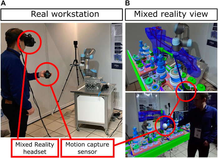
FIGURE 11. An industrial use case involving one UR5 robot. The real workstation (A) is augmented with a virtual 3D environment and safety criteria (B): robot swept volume and velocity, minimum distance with the user. The user is immersed inside the digital twin thanks to a mixed reality headset (HTC Vive + Zed mini camera).
Inside the digital twin, the swept volume of the robot’s end effector along the whole trajectory is displayed. The end-effector’s velocity and kinetic energy are also monitored. Safety areas are located around the robot’s tool and around the robot’s base. The operator’s position is tracked by one motion capture sensor (a HTC Vive Tracker) located on the operator’s hand: it is used to compute the minimum distance to the robot and the intrusion inside safety areas.
This use case shows the benefits of using mixed reality to augment the robot’s environment with a virtual one, to better understand the robot’s trajectories and safety issues, without any threat for the operators.
The SEEROB framework was tested in a second mixed environment involving a small Niryo One robot, for education purposes (see Figure 12). The demonstrator involves a real Niryo One robot and a real conveyor and simulates the picking of industrial parts from a sliding ramp to the conveyor. The robot’s workcell and the parts to pick are virtual.
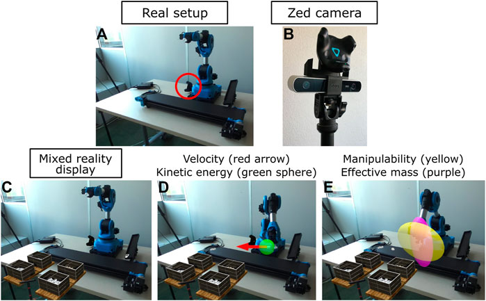
FIGURE 12. A use case for education involving a real Niryo One robot and a real conveyor. The real setup (A) is augmented with virtual elements thanks to a Zed camera tracked with a HTC Vive Tracker (B). The mixed reality display (C) shows virtual parts to pick and a virtual workcell. The robot velocity and kinetic energy (D), and the manipulability and effective mass ellipsoids (E) are also displayed.
The Niryo One robot controller is based on ROS. The real-time communication with the robot controller is achieved through the Unity Robotics Hub: robot Cartesian trajectories are defined inside Unity3D and sent to the controller, while the robot joint configuration is sent back from the controller to Unity3D to display a graphical model of the robot. The XDE physics engine uses this desired robot joint configuration to control a physics-based twin of the robot. Contrary to the graphical robot, the physics robot can give data on its velocity, energy, effective mass and efforts.
The digital twin is displayed using a mixed reality device (a Zed camera tracked with a HTC Vive Tracker). The space calibration between the digital twin and the real setup is performed with a HTC Vive Tracker located next to the robot (see Figure 12). The safety criteria computed by the physics engine are superimposed on the real setup thanks to the mixed reality device: velocity, kinetic energy, manipulability and effective mass ellipsoids.
In some situations, the real workstation does not exist at all and the digital twin is purely virtual. In such cases, the digital twin is entirely represented with 3D models and operators are immersed inside the environment thanks to virtual reality headsets. Virtual robots may be controlled thanks to robot emulators or offline trajectories. The SEEROB framework was tested in two such environments.
The first use case (see Figure 13) is composed of a factory line with three robots (two Kuka iiwa and one Universal Robot UR10) and one operator working together. The digital twin 3D model was imported with PiXYZ. Robot trajectories were imported from Delmia as Excel files. The user is immersed inside the digital twin thanks to a virtual reality headset (HTC Vive with two controllers). Safety areas were placed at specific locations in the virtual environment (next to robots) to monitor the operator’s intrusion. The minimum distance between the operator and the robots is also monitored. For each robot, the velocity and kinetic energy of the end-effector and the elbow are monitored and displayed.
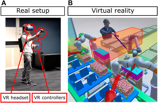
FIGURE 13. An industrial use case involving two Kuka iiwa robots and one UR10 robot. The user is immersed inside the digital twin thanks to a virtual reality headset (A). The simulation computes the robot velocities and kinetic energies, safety area intrusions and the minimum distance between the user and the robots (B).
The second use case is composed of a virtual Niryo One robot (scaled by a factor 10 to represent an industrial robot) working on an assembly line together with an operator. The demonstrator simulates the picking of industrial parts: the robot has to move the parts from a ramp to a conveyor, while the operator has to take the parts and place them inside specific boxes. The user is immersed inside the digital twin thanks to a virtual reality headset (Oculus Quest) and interacts with the virtual parts with virtual reality controllers (see Figure 14). The operator may also be tracked by a Kinect Azure camera to evaluate the workstation ergonomics.
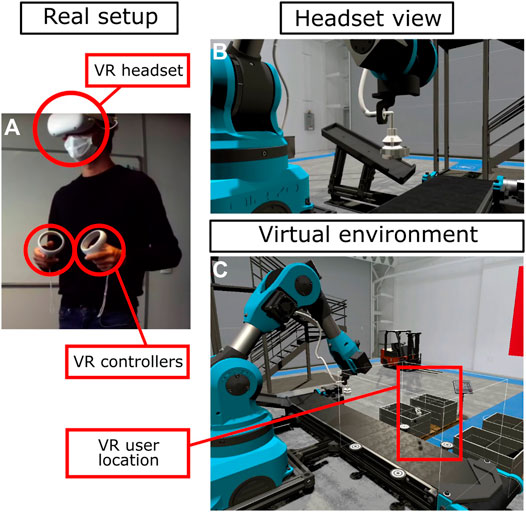
FIGURE 14. A virtual reality use case involving a Niryo One robot. The user is immersed inside the digital twin thanks to a virtual reality headset (A). The headset view is displayed in the (B) picture, while the whole virtual environment is shown in the (C) picture.
These use cases show the benefits of using a digital twin (with the robots’ real trajectories) and virtual reality to monitor and compare different human-robot collaboration scenarios, without having access to the real setup.
In some use cases, multiple users share the same representation of a digital twin and collaborate together inside the same simulation. These users may be located in the same place, by using colocated mixed or virtual reality headsets, or they may be located remotely in different places. Each user may choose to display the digital twin in their preferred way, in mixed or virtual environments. This is especially useful when engineers have to collaborate together on the same workcell design, when engineers have to understand what is happening in a remote robot workstation while staying at their office, or when resources are not located in the same environments (for example, robot controllers may be available in the factory plant and motion capture setups may be available in laboratories).
The SEEROB framework was tested in a laboratory demonstrator illustrating multi-user environments (see Figure 15). The demonstrator is based on the setups described in Section 3.2.2; Section 3.3.2. It involves a first environment, with a real Niryo One robot, a real conveyor and a mixed reality display, and a second environment used for virtual reality simulation and operator motion capture. Both environments communicate with each other on the same local network and share the same digital twin state. The robot state from the real setup is accessed by the physics engine and shared to both environments, so that the virtual robot of the digital twin moves according to the real robot movements. The user state (inputs and movements) is also accessed by the physics engine and shared to both environments.
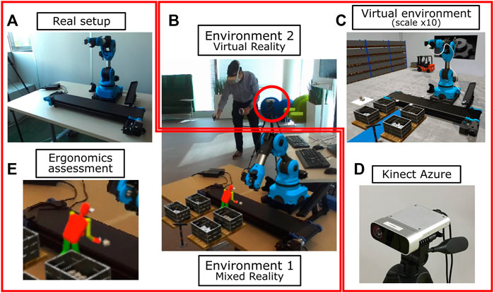
FIGURE 15. A demonstrator with multi-user environments involving a Niryo One robot (A). The first environment is used to access robot data and for mixed reality display (B). The second environment is used for virtual reality simulation inside a scaled virtual environment (C). Both environments share the same digital twin state, with different representations and different scales. A Kinect Azure camera (D) and red circle) is used to evaluate the ergonomics posture of the operator (E).
While the user is evolving in the second environment, interacting with the virtual robot and virtual parts, the operator’s movements and postures may be observed through the mixed reality display of the first environment (see Figure 15), to augment the real setup with virtual operations. In our demonstrator, the two environments are displayed with a different scale (the virtual environment is ten times bigger than the real setup): this is performed to account for the small size of the Niryo One robot in the real setup, while interacting with a virtual robot of a relevant size in an industrial context.
The SEEROB framework proposes a new approach for the safety and ergonomics evaluation of cobotic workstations. It differs from other frameworks on various aspects:
• It enables direct communication with robot controllers and automata, making the safety and ergonomics assessments more relevant and closer to the real situation;
• It uses a precise physics engine to animate a physics-based digital twin and compute precise safety criteria, enabling a finer tuning of the workstation configuration;
• It uses extended reality technologies to immerse users inside the digital twin, helping the operators and engineers better understand safety and ergonomics issues;
• It uses motion capture technology to perform precise ergonomics assessments directly inside the digital twin.
The SEEROB framework may be constrained by some aspects. First, it relies on precise parameters of the digital twin, including robot masses, inertia, maximum torques. These parameters are not always accessible and given by robot constructors. Therefore, estimations and approximations are sometimes needed and can make the safety assessment less relevant. Computations can be performed by taking the worst case scenarios and maximum estimations of the missing values, but this can lead to restrictive evaluations.
Secondly, getting real-time data from robot controllers is a strong benefit but often needs specific developments to adapt to each robot connection protocols. Nowadays, there exists few standard protocols unifying all robot controllers and having specific developments seems inevitable. The ROS platform could be a good opportunity but still does not offer the support for all robot controllers. Our on-going work is focusing on OPC-UA protocol and the AutomationML format, which seem a new promising approach for digital twin modelling and communication.
Thirdly, our approach does not enable feedback on the control of the real workstation. Users can still send events from the virtual environment to the real workstation, such as triggering a virtual lever to send a new state to an automaton, but no modifications are applied to the real robot controllers. This could be possible in a robotics design approach. However, since our approach is based on safety and ergonomics evaluation, robot controllers and trajectories are considered without any modifications in order to provide a focused report. If modifications on controllers and trajectories are needed, they must be performed before making a second different analysis.
Fourth, the SEEROB framework uses motion capture systems from the animation or virtual reality fields. These systems were sufficient in the context of our study, but a deeper evaluation of the systems accuracy should be performed to know the systems limitations. Moreover, for virtual reality use cases, the effects of prolonged virtual reality immersion on users (Guo et al., 2020) should be evaluated with dedicated user studies involving stress tests and questionnaires.
Finally, the SEEROB framework provides technical tools to assess cobotic workstations by giving objective numerical data, such as safety criteria or ergonomics scores. This data does not provide a complete assessment of the workstation and needs to be analyzed and post-processed by people with specific knowledge on safety regulations and ergonomics. Additional subjective data, such as the operator’s fatigue or mental workload, also have to be taken into account. Our current work is focusing on providing people with an intuitive methodology to process this data, and illustrating this methodology with additional industrial use cases.
Nonetheless, we believe that the SEEROB framework may provide a useful basis for engineers and operators to better design their workstations and better understand safety and ergonomics issues, in an easy and interactive way. We will continue working on the SEEROB framework to improve it with more safety and ergonomics criteria and to make it even more spread among industrial end-users. In details, the next steps of this work will be focused on making the safety criteria more relevant with regard to the actual and future safety regulations, on integrating additional ergonomics rules, on applying the framework to specific industrial use cases and to provide a deeper analysis of the framework’s outputs, especially by comparing results from standard analyses (as performed today by hand) and results provided by our tool.
The original contributions presented in the study are included in the article/Supplementary Material, further inquiries can be directed to the corresponding author.
Written informed consent was obtained from the individual(s) for the publication of any identifiable images or data included in this article.
Framework development, VW and FK; Methodology, VW, FK, CA, and AL; Supervision, CA; Demonstrators, VW, AL, and AB; Writing original draft, all authors.
This work has been supported by the several projects from the FactoryLab consortium9.
Author AL was employed by the company Light & Shadows.
The remaining authors declare that the research was conducted in the absence of any commercial or financial relationships that could be construed as a potential conflict of interest.
All claims expressed in this article are solely those of the authors and do not necessarily represent those of their affiliated organizations, or those of the publisher, the editors and the reviewers. Any product that may be evaluated in this article, or claim that may be made by its manufacturer, is not guaranteed or endorsed by the publisher.
The authors would like to thank the industrial partners from the FactoryLab consortium for supporting the framework development and providing industrial use cases, and especially Fabien d’Andrea from Stellantis. The authors would also like to thank the FFLOR platform and Alice Magisson for providing additional use cases.
2https://www.pixyz-software.com/.
4https://github.com/Unity-Technologies/Unity-Robotics-Hub.
6https://developer.nvidia.com/nvidia-cloudxr-sdk.
Albert, J. A., Owolabi, V., Gebel, A., Brahms, C. M., Granacher, U., and Arnrich, B. (2020). Evaluation of the Pose Tracking Performance of the Azure Kinect and Kinect V2 for Gait Analysis in Comparison with a Gold Standard: A Pilot Study. Sensors 20, 5104. doi:10.3390/s20185104
Alexopoulos, K., Mavrikios, D., and Chryssolouris, G. (2013). Ergotoolkit: an Ergonomic Analysis Tool in a Virtual Manufacturing Environment. Int. J. Computer Integrated Manufacturing 26, 440–452. doi:10.1080/0951192x.2012.731610
Bernhardt, R., Schreck, G., and Willnow, C. (1994). “The Realistic Robot Simulation (Rrs) Interface,” in IFAC Proceedings Volumes IFAC Workshop on Intelligent Manufacturing Systems 1994 (IMS’94), Vienna, Austria, 13-15 June, 27, 321–324. doi:10.1016/S1474-6670(17)46044-7
Bernhardt, R., Schreck, G., and Willnow, C. (2000). Virtual Robot Controller (Vrc) Interface. Automation Transportation Technology - Simulation Virtual Reality, 115–120.
Castro, P. R., Högberg, D., Ramsen, H., Bjursten, J., and Hanson, L. (20192018). “Virtual Simulation of Human-Robot Collaboration Workstations,” in Proceedings of the 20th Congress of the International Ergonomics Association (Springer, Cham, Switzerland: IEA), 250–261. doi:10.1007/978-3-319-96077-7_26
Chiacchio, P., Bouffard-Vercelli, Y., and Pierrot, F. o. (1997). Force Polytope and Force Ellipsoid for Redundant Manipulators. J. Robotic Syst. 14, 613–620. doi:10.1002/(sici)1097-4563(199708)14:8<613:aid-rob3>3.0.co;2-p
Drillis, R., Contini, R., and Bluestein, M. (1964). Body Segment Parameters; a Survey of Measurement Techniques. Artif. Limbs 8, 44–66.
Dröder, K., Bobka, P., Germann, T., Gabriel, F., and Dietrich, F. (2018). A Machine Learning-Enhanced Digital Twin Approach for Human-Robot-Collaboration. Proced. CIRP 76, 187–192. doi:10.1016/j.procir.2018.02.010
Eichler, P., Rashid, A., Nasser, I. A., Halim, J., and Bdiwi, M. (2021). “Modular System Design Approach for Online Ergonomics Assessment in Agile Production Environment,” in 2021 30th IEEE International Conference on Robot Human Interactive Communication (Vancouver, Canada: RO-MAN), 1003–1010. doi:10.1109/RO-MAN50785.2021.9515437
Ferraguti, F., Bertuletti, M., Landi, C. T., Bonfè, M., Fantuzzi, C., and Secchi, C. (2020). A Control Barrier Function Approach for Maximizing Performance while Fulfilling to Iso/ts 15066 Regulations. IEEE Robotics Automation Lett. 5, 5921–5928. doi:10.1109/LRA.2020.3010494
Filipenko, M., Angerer, A., Hoffmann, A., and Reif, W. (2020). Opportunities and Limitations of Mixed Reality Holograms in Industrial Robotics. CoRR abs/, 2001, 08166.
Glogowski, P., Lemmerz, K., Hypki, A., and Kuhlenkötter, B. (2019). “Extended Calculation of the Dynamic Separation Distance for Robot Speed Adaption in the Human-Robot Interaction,” in 2019 19th International Conference on Advanced Robotics (Belo Horizonte, Brazil: ICAR), 205–212. doi:10.1109/ICAR46387.2019.8981635
Guo, J., Weng, D., Fang, H., Zhang, Z., Ping, J., Liu, Y., et al. (2020). “Exploring the Differences of Visual Discomfort Caused by Long-Term Immersion between Virtual Environments and Physical Environments,” in 2020 IEEE Conference on Virtual Reality and 3D User Interfaces (Atlanta, GA: VR), 443–452. doi:10.1109/VR46266.2020.00065
Haddadin, S., Haddadin, S., Khoury, A., Rokahr, T., Parusel, S., Burgkart, R., et al. (2012). On Making Robots Understand Safety: Embedding Injury Knowledge into Control. Int. J. Robotics Res. 31, 1578–1602. doi:10.1177/0278364912462256
Hignett, S., and McAtamney, L. (2000). Rapid Entire Body Assessment (REBA). Appl. Ergon. 31, 201–205. doi:10.1016/s0003-6870(99)00039-3
ISO (2016). International Organization for Standardization - Technical Specification - ISO/TS 15066:2016 – Robots and Robotic Devices – Collaborative Robots.
Joseph, L., Pickard, J. K., Padois, V., and Daney, D. (2020). “Online Velocity Constraint Adaptation for Safe and Efficient Human-Robot Workspace Sharing,” in International Conference on Intelligent Robots and Systems, Las Vegas, United States.
Jubien, A., Gautier, M., and Janot, A. (2014). Dynamic Identification of the Kuka Lwr Robot Using Motor Torques and Joint Torque Sensors Data. IFAC Proc. Volumes19th IFAC World Congress 47, 8391–8396. doi:10.3182/20140824-6-ZA-1003.01079
Khatib, O. (1995). Inertial Properties in Robotic Manipulation: An Object-Level Framework. Int. J. Robotics Res. 14, 19–36. doi:10.1177/027836499501400103
Kirschner, R. J., Mansfeld, N., Peña, G. G., Abdolshah, S., and Haddadin, S. (2021). “Notion on the Correct Use of the Robot Effective Mass in the Safety Context and Comments on Iso/ts 15066,” in 2021 IEEE International Conference on Intelligence and Safety for Robotics (Tokoname, Japan: ISR), 6–9. doi:10.1109/ISR50024.2021.9419495
Kousi, N., Gkournelos, C., Aivaliotis, S., Giannoulis, C., Michalos, G., and Makris, S. (2019). Digital Twin for Adaptation of Robots’ Behavior in Flexible Robotic Assembly Lines7th International Conference on Changeable, Agile, Reconfigurable and Virtual Production (CARV2018). Proced. Manufacturing 28, 121–126. doi:10.1016/j.promfg.2018.12.020
Lacevic, B., Zanchettin, A. M., and Rocco, P. (2020). “Towards the Exact Solution for Speed and Separation Monitoring for Improved Human-Robot Collaboration,” in 2020 29th IEEE International Conference on Robot and Human Interactive Communication (Naples, Italy: RO-MAN), 1190–1195. doi:10.1109/RO-MAN47096.2020.9223342
Lachner, J., Allmendinger, F., Hobert, E., Hogan, N., and Stramigioli, S. (2021). Energy Budgets for Coordinate Invariant Robot Control in Physical Human–Robot Interaction. Int. J. Robotics Res. 40, 968–985. doi:10.1177/02783649211011639
Lynch, K. M., and Park, F. C. (2017). Modern Robotics - Mechanics, Planning, and Control. Cambridge University Press.
Malik, A. A., and Brem, A. (2021). Digital Twins for Collaborative Robots: A Case Study in Human-Robot Interaction. Robotics and Computer-Integrated Manufacturing 68, 102092. doi:10.1016/j.rcim.2020.102092
Mansfeld, N., Hamad, M., Becker, M., Marin, A. G., and Haddadin, S. (2018). Safety Map: A Unified Representation for Biomechanics Impact Data and Robot Instantaneous Dynamic Properties. IEEE Robotics Automation Lett. 3, 1880–1887. doi:10.1109/LRA.2018.2801477
Marvel, J. A., and Norcross, R. (2017). Implementing Speed and Separation Monitoring in Collaborative Robot Workcells. Robot Comput. Integr. Manuf 44, 144–155. doi:10.1016/j.rcim.2016.08.001
Matsas, E., Vosniakos, G.-C., and Batras, D. (2018). Prototyping Proactive and Adaptive Techniques for Human-Robot Collaboration in Manufacturing Using Virtual Reality. Robot. Comput.-Integr. Manuf. 50, 168–180. doi:10.1016/j.rcim.2017.09.005
McAtamney, L., and Nigel Corlett, E. (1993). RULA: a Survey Method for the Investigation of Work-Related Upper Limb Disorders. Appl. Ergon. 24, 91–99. doi:10.1016/0003-6870(93)90080-s
Merlhiot, X. (2007). “A Robust, Efficient and Time-Stepping Compatible Collision Detection Method for Non-smooth Contact between Rigid Bodies of Arbitrary Shape,” in Proceedings of the Multibody Dynamics 2007 ECCOMAS Thematic Conference.
Orsolino, R., Focchi, M., Mastalli, C., Dai, H., Caldwell, D. G., and Semini, C. (2018). Application of Wrench-Based Feasibility Analysis to the Online Trajectory Optimization of Legged Robots. IEEE Robotics Automation Lett. 3, 3363–3370. doi:10.1109/LRA.2018.2836441
Pavlou, M., Laskos, D., Zacharaki, E. I., Risvas, K., and Moustakas, K. (2021). Xrsise: An Xr Training System for Interactive Simulation and Ergonomics Assessment. Front. Virtual Reality 2, 17. doi:10.3389/frvir.2021.646415
Saenz, J., Behrens, R., Schulenburg, E., Petersen, H., Gibaru, O., Neto, P., et al. (2020). Methods for Considering Safety in Design of Robotics Applications Featuring Human-Robot Collaboration. Int. J. Adv. Manufacturing Technology 107, 2313–2331. doi:10.1007/s00170-020-05076-5
Saenz, J., Herbster, S., Scibilia, A., Valori, M., Fassi, I., Behrens, R., et al. (2021). Covr - Using Robotics Users’ Feedback to Update the Toolkit and Validation Protocols for Cross-Domain Safety of Collaborative Robotics
Scalera, L., Giusti, A., Cosmo, V., Riedl, M., Vidoni, R., and Matt, D. (2020). Application of Dynamically Scaled Safety Zones Based on the Iso/ts 15066:2016 for Collaborative Robotics. Int. J. Mech. Control. 21, 41–50.
Schaub, K. G., Mühlstedt, J., Illmann, B., Bauer, S., Fritzsche, L., Wagner, T., et al. (2012). Ergonomic Assessment of Automotive Assembly Tasks with Digital Human Modelling and the ’ergonomics Assessment Worksheet’ (Eaws). Int. J. Hum. Factors Model. Simulation 3, 398.
Skuric, A., Padois, V., and Daney, D. (2020). On-line Force Capability Evaluation Based on Efficient Polytope Vertex Search. CoRR abs/, 2011, 05226.
Stürz, Y. R., Affolter, L. M., and Smith, R. S. (2017). Parameter Identification of the Kuka Lbr Iiwa Robot Including Constraints on Physical Feasibility. IFAC-PapersOnLine 20th IFAC World Congress 50, 6863–6868. doi:10.1016/j.ifacol.2017.08.1208
Svarný, P., Rozlivek, J., Rustler, L., and Hoffmann, M. (2020). 3d Collision-Force-Map for Safe Human-Robot Collaboration. CoRR abs/2009, 01036.
Tika, A., Ulmen, J., and Bajcinca, N. (2020). “Dynamic Parameter Estimation Utilizing Optimized Trajectories,” in 2020 IEEE/RSJ International Conference on Intelligent Robots and Systems IROS (Las Vegas, NV: IEEE), Las Vegas, NV, USA, 24 Oct.-24 Jan. 2021, 7300–7307. doi:10.1109/IROS45743.2020.9341518
Vemula, B., Matthias, B., and Ahmad, A. (2018). A Design Metric for Safety Assessment of Industrial Robot Design Suitable for Power- and Force-Limited Collaborative Operation. Int. J. Intell. Robot Appl. 2, 226–234. doi:10.1007/s41315-018-0055-9
Weistroffer, V., Paljic, A., Fuchs, P., Hugues, O., Chodacki, J.-P., Ligot, P., et al. (2014). “Assessing the Acceptability of Human-Robot Co-presence on Assembly Lines: A Comparison between Actual Situations and Their Virtual Reality Counterparts,” in The 23rd IEEE International Symposium on Robot and Human Interactive Communication, 377–384. doi:10.1109/ROMAN.2014.6926282
Wojtynek, M., and Wrede, S. (2020). “Interactive Workspace Layout Focusing on the Reconfiguration with Collaborative Robots in Modular Production Systems,” in ISR 2020; 52th International Symposium on Robotics, 1–8.
Zanchettin, A. M., Ceriani, N. M., Rocco, P., Ding, H., and Matthias, B. (2016). Safety in Human-Robot Collaborative Manufacturing Environments: Metrics and Control. IEEE Trans. Automation Sci. Eng. 13, 882–893. doi:10.1109/TASE.2015.2412256
Keywords: digital twin, cobotics, safety, ergonomics, virtual reality, mixed reality, physics
Citation: Weistroffer V, Keith F, Bisiaux A, Andriot C and Lasnier A (2022) Using Physics-Based Digital Twins and Extended Reality for the Safety and Ergonomics Evaluation of Cobotic Workstations. Front. Virtual Real. 3:781830. doi: 10.3389/frvir.2022.781830
Received: 23 September 2021; Accepted: 10 January 2022;
Published: 09 February 2022.
Edited by:
Nicola Pedrocchi, Istituto di Sistemi e Tecnologie Industriali Intelligenti per il Manifatturiero Avanzato, ItalyReviewed by:
Cristina Nuzzi, University of Brescia, ItalyCopyright © 2022 Weistroffer , Keith , Bisiaux , Andriot and Lasnier . This is an open-access article distributed under the terms of the Creative Commons Attribution License (CC BY). The use, distribution or reproduction in other forums is permitted, provided the original author(s) and the copyright owner(s) are credited and that the original publication in this journal is cited, in accordance with accepted academic practice. No use, distribution or reproduction is permitted which does not comply with these terms.
*Correspondence: Vincent Weistroffer , dmluY2VudC53ZWlzdHJvZmZlckBjZWEuZnI=
Disclaimer: All claims expressed in this article are solely those of the authors and do not necessarily represent those of their affiliated organizations, or those of the publisher, the editors and the reviewers. Any product that may be evaluated in this article or claim that may be made by its manufacturer is not guaranteed or endorsed by the publisher.
Research integrity at Frontiers

Learn more about the work of our research integrity team to safeguard the quality of each article we publish.