 Leonardo Frizziero
 Giampiero Donnici
 Marco Freddi
- Alma Mater Studiorum – University of Bologna, Bologna, Italy
This paper is intended to offer a cue for optimizing a generic disassembly process for maintenance purposes. Through the use of a cutting-edge technology such as augmented reality, a key tool that makes it immediate to tell operators what they need to do, this can be made possible as never before within companies. A first aim of the work is to define the optimal disassembly sequence that can lead to the extraction of a target component of the assembly minimizing the number of parts to be removed, applying two methodologies within the framework of Design for Disassembly. Thus, the most important goal is to show and teach to maintenance technicians which steps they should follow in order to efficiently carry out the repair process built on that sequence so that they can work on a product while learning in parallel what they need to do exactly at the same time. This could be useful in case a component replacement becomes necessary especially because nowadays it is still performed inefficiently and lacks a rigorous logic and methodology aimed at its efficiency in companies.
1. Introduction
In the industrial environment, the acronym “DfD” represents the discipline of Design for Disassembly, thus the set of activities dedicated to the realization of a “disassembly list” for the parts belonging to a product (Harjula et al., 1996). The purpose is to obtain a list of operations to be carried out by maintenance workers in order to optimize the time and cost of the procedure (Haapala et al., 2013). It is understandable how much time we could lose when the list of operations to be performed is unclear (Boothroyd and Alting, 1992). Typically, what happens is that when faced with an even particularly complex product, a lot of work needs to be done to get a “target” component to be repaired or replaced (Umeda et al., 2015). A maintenance procedure can be either corrective or preventive. Only in the second case a product's life can be extended, as a component that is part of it and necessary to ensure its functionality is replaced before it is damaged. After the damage has occurred, on the other hand, it is possible that other elements of the product's architecture have also been subjected to such failure and wear and tear that their reuse is not considered (Lowe and Bogue, 2007). In many circumstances, most of the materials needed to produce new components can be recovered. The DfD has been built specifically to enable greater recovery of parts and materials, a significant improvement in the time and cost efficiency of industrial maintenance, and optimal development of the operators' technical abilities (Favi et al., 2012). Since the main objective becomes that of defining an optimal disassembly sequence, company employees should follow the list of operations for removing the various components within the assembly indicated by who carried out the study. In terms of time and cost the company gains enormously because the probability of error is automatically minimized, providing a “to-do list” even to those who do not have a clear idea of the process.
One of the basic rules of DfD requires that the most important components should ideally be placed in easily accessible locations during maintenance (Zussman et al., 1994). With regard to the fasteners present in the assembly (screws, nuts, bolts, etc.), it can be said that they rarely represent critical components as they do not participate in fulfilling the functionality for which that particular design is being realized. For this reason, their removal is always assumed to be quick and easy. Their disassembly, by the way, is almost never done in a destructive form. In this sense, their structural integrity and functionality can always be preserved, allowing them to be reused in the future.
There are many topics concerning Design for Disassembly. It is impossible to omit mentioning the one concerning the choice of materials for the project. Nowadays, in fact, it is no longer possible to rely solely on structural checks or analysis of the mechanical behavior of materials to choose the most appropriate ones. In order to make the project legitimate also from a social, ethical and eco-sustainable point of view, it is necessary to be able to guarantee that most of the materials used will be easily disposable and potentially recyclable 1 day (Akinade et al., 2017). Materials that are not compatible with each other must be properly disposed of. A large number of considerations about the disposal of the product and its components should counterintuitively be made at the time of its conceptualization. This serves to give the project an initial gain that involves both purely economic aspects (considering that, for example, maintenance costs on that product will be paid by the company commercializing it in the future) and ethical and social aspects (to ensure that the product will be completely disposable without special contraindications) (Favi et al., 2016). So, another purpose is to minimize the number of different types of components used (Papakostas et al., 2015). This means that if only one type of screw can be chosen for all the connections between the parts to be designed then this should indeed be done. From environmental protection to sustainable economics, from the safety of business operators to consumer health, the issues involved in DfD are endless (Smith and Chen, 2011). While several methodologies developed in recent years and well-known in the industrial sector, such as QFD, offer great advantages in the context of making new product development more efficient, DFD already lays the foundation for its management at the end of its useful life (Popoff and Millet, 2017).
1.1. Application of augmented reality for Design for Disassembly
To understand what exactly augmented reality is, we can proceed by comparing it directly to the similar, but different, virtual reality. Video games constitute an example of VR (Virtual Reality). The VR world is completely artificial and devoid of direct references to reality. Augmented reality, on the other hand, allows us to add elements to the visualization of the real environment around us, through the use of special tools such as HoloLens or AR viewers. Based on the assumption that only with the help of the five senses is it possible to perceive the world around us, augmented reality stands at the technological level as an additional sense that a person can make use of Santi et al. (2021). It might be thought that this technology is still part of a future quite far from the present. However, many companies are already finding several benefits from its extensive use. An initial model related to the concept of a new product directly made in an augmented reality environment allows its immediate visualization in the real world. Studying the overall dimensions of a machine tool to be placed in a specific area of a department allows not to go through the simple CAD interface route but rather to see the product exactly as it will be. Very often, then, it happens that time and resources are spent solely on ensuring its performance and functionality. Instead, thorough evaluations of its disassembly can pave the way for innovative and, above all, optimal architectural solutions right from the start (Berg et al., 2013). As will be seen below, again, the ability to visualize a virtual prototype in AR makes all the difference. Thanks to the use of references in nature (even just a photograph or a symbol) called “markers,” it is possible to place an element of our interest that can be visualized thanks to augmented reality in the real world, in correspondence with that chosen artificial reference (this will become clearer later in the article). One of the major limitations regarding an augmented reality application involves precisely the need to display the virtual model of the product in nature at a predetermined location. For example, in the case of a centrifugal pump that is part of a water system, visualizing it at the exact location where it will be inserted prior to its physical prototyping can lead to better design considerations (Eswaran et al., 2023). As will be seen, however, it is not mandatory to use complex and expensive sensor systems or pushed cutting-edge technologies when making use of a marker-based AR system. At virtually no cost, it will be demonstrated here that a sufficiently graphically complex marker can be made to enable optimal position recognition at the viewer. It would be easier to design it respecting both dimensional and aesthetic constraints. Who will have to present it to the market and sell it will also find it more advantageous to show it to future consumers by employing AR technology. In fact, it is the only one that can place the product in the real world. Still, it becomes possible to avoid more the construction of a physical prototype, more effectively assessing the safety conditions of the people who will have to interface with that product. The AR technology used here is “marker based.” This means that in order to display at a specific location in the real environment the virtual model of the desired product, it is needed to frame a real object in nature. A glass characterized by a particular shape or a plastic object could be two examples of “markers.” Actually, even by framing a drawing or a picture may be sufficient to place the virtual model above it. In the case studied, the marker is a simple image, however this will no doubt become clearer later. Thus, the basic idea is to combine DfD theory, which can lead to the definition of one or more optimal disassembly sequences, with augmented reality. Thanks to an AR application designed to interface with hypothetical industrial product maintenance workers, it will be possible to show them the optimal sequence derived within DfD in probably the clearest and most convenient way possible. The workflow concerning the use of Design for Disassembly linked to Augmented Reality is presented in Figure 1. The second section will describe two methods known in the literature in the field of DfD that are useful for defining an optimal disassembly sequence of a product. The last section, on the other hand, is devoted to the analysis of an augmented reality application whose main purpose is to demonstrate how by coping with low expenditures in terms of cost and time a tool with very high potential can be offered to the companies of the present time. In fact, it will make possible the optimization of a maintenance or assembly process in parallel with effective and visually impactful training for the benefit of the operators who will have to perform such tasks quickly and safely. As also already demonstrated in the literature, time savings resulting from the use of augmented reality in the course of the company's business activities is not only theoretical but directly verifiable (Osti et al., 2017). It is enough to think that the processes of understanding the tasks to be performed and their realization are no longer divided into two distinct and serial time phases but into a single phase in parallel. There is no longer a need for the second to occur only after the completion of the first (Chang et al., 2017).
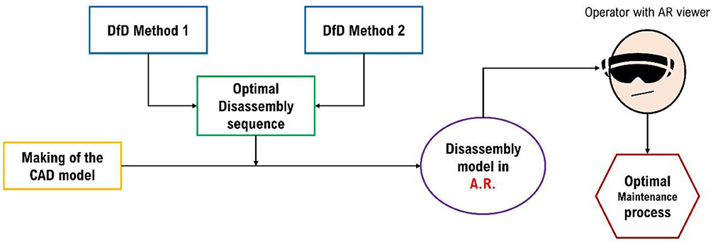
Figure 1. Workflow concerning DfD and AR for the maintenance process.
2. Case study
The case study of the work concerns the disassembly analysis of a float condensate drain. This assembly is interfaced with ducts designed for steam distribution within industrial plant systems. Within an unloader such as the one under consideration, it is made possible to remove condensed steam as soon as it has formed due to heat loss or the presence of heat exchangers. The main advantage is for the system's efficiency, which improves. The use of an internal float makes it possible to automatically actuate the valve, which opens and allows water to flow out of the system. The presence of an artificial lever actuation system, however, is necessary in the event of damage to the float, as shown in Figure 2.
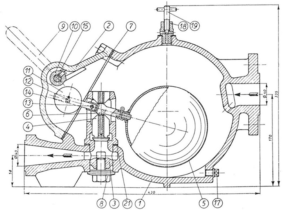
Figure 2. Drawing of the assembly (not all BOM components are shown).
In Table 1 the assembly's Bill of Materials is shown.
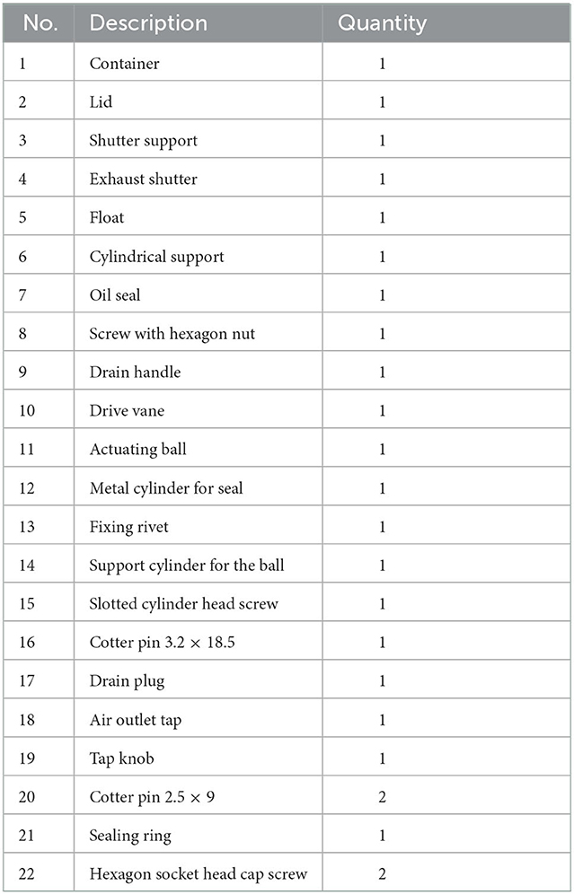
Table 1. Bill of materials.
To give a better understanding of what kind of assembly we are talking about two representations of it are offered in the next image. As can be seen in Figure 3, the interior of the condensate drain was completely modeled in CAD (Autodesk Inventor), without neglecting any type of components.
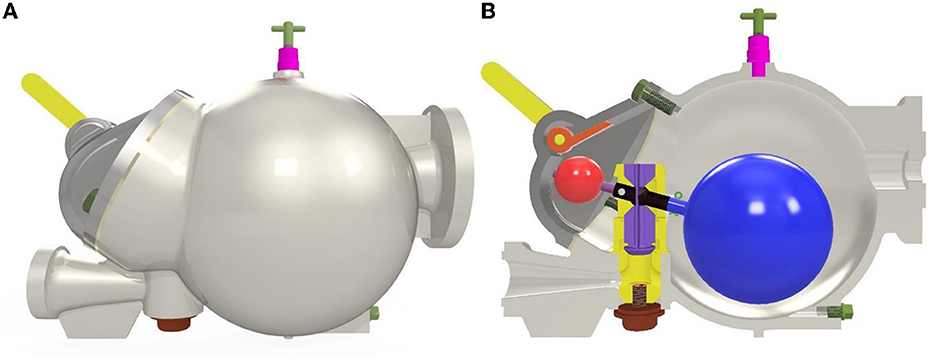
Figure 3. (A) Exterior view of the assembly; (B) view of internal components in the CAD environment.
3. DfD methods
Two methods are proposed to find the optimal disassembly sequence. The first is a very visual and practical method, while the second can also be considered for a computerized application of the problem. In fact, as will be seen, the second method is constructed using matrices of 0 and 1 containing the entire assembly information of the various components of the steam trap.
3.1. First method
The first proposed method is described clearly in literature (Yi et al., 2007). The goal is to obtain a disassembly sequence to reach the target component that has to be removed. The first thing to do is precisely to choose what the latter is. Upon completion of the “wave” graph discussed shortly, it is then possible to opt for the sequence that disassembles fewer parts, the one that wastes less time, or the one that results in a lower disassembly cost (Cong et al., 2017). A generic assembly component can be classified in two ways:
• d-dependant: when an integer number d of generic components must be extracted to extract the chosen component.
• 1-dependant: when after only one removal of another generic component the target component is already freely removable.
The determination of the various disassembly sequences can be performed using the so-called “disassembly wave.” We can imagine that the target component is located at the origin center of the wave. Its propagation starts as a series of concentric circumferences spreading out in a plane. At the first instant of time τ1, purely theoretical, all components in contact with the target will be touched by the wave. At the next time instant, all components close to those previously touched by the wave will be touched, and so on. This procedure is carried on until a generic final instant τn, reached when all components of the assembly have already been involved. According to what has just been said, the first components to be removed will be those located on the outermost ring of the graph. It should be noted that it will not necessarily be necessary to remove all the components placed on each ring before moving on to the innermost ones. The goal is precisely to minimize the number of removals to reach the target. In the case under consideration, this is number 4, namely the exhaust shutter, precisely because it is one of the components placed “deepest” in the model. Its probability of failure due to wear of the central spherical invitation, by the way, is particularly high. Since the assembly is a very simple object with few components, the disassembly logic is always the same. As a first step, it will certainly be necessary to remove the hexagon socket head cap screws (22) in order to subsequently succeed in disassembling the lid (2), an action that is indispensable in order to be able to reach the components inside the housing. Components 20, 12, 11, and 14 with 16 could be either disassembled with component 4 still attached or with the whole assembly disassembled from the base, component 1. Component 14 is attached to 6 with a rivet. Should one wish to opt for its removal, the rivet (13) must be demolished. Component 4 is removable from 3 only when component 6 has been removed.
According to what has been said so far, it is possible to opt for two alternative sequences, as can be deduced from the graph depicted in Figure 4:
• 22, 2, 8, 3, 20, 12, 11, 16, 5, 14–6, 4. Disassembly with previous removal of the entire shutter system.
• 22, 2, 20, 12, 11, 16, 5, 14–6, 8, 3, 4. Disassembly with the shutter system fixed at the base.
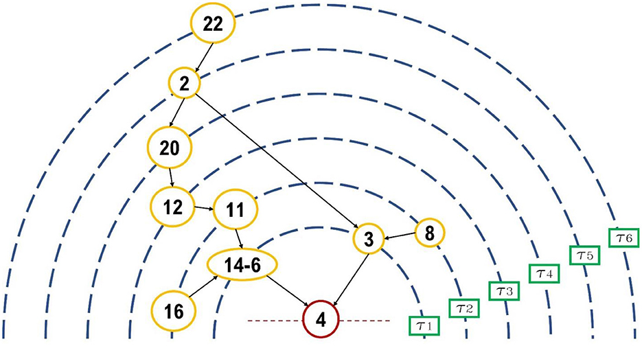
Figure 4. Disassembly wave logical diagram.
3.2. Second method
The second proposed method is undoubtedly more technical and computerizable than the first one (Tao et al., 2018). The application of this algorithm starts by defining a matrix representing all the spatial constraints of removals present between the various components of the product. It is referred to as the “Disassembly Precedence Matrix” (DPM), and it is square. Its size is equal to the number of parts in the assembly. Once it is completely defined, one can proceed with the disassembly of the first bolted connections (referred to precisely as fasteners) by removing the row and column related to the removed component in the matrix. The proposed method to represent the architecture of the system mathematically and efficiently is particularly interesting, as it makes use of simple sequences consisting of six digits within each cell of the matrix. Each digit of the sequence represents the Cartesian direction of removal of a component (–x, +x, –y, +y, –z, +z). Thus, comparing an element on a row (i) against another element on any column (j), one must proceed by entering a 1 each time component j prevents the removal of i in that specific direction considered. One can see how a computerized application of this method can be useful in the case of very complex assemblies consisting of a high number of components. If the compilation of the matrix is done correctly it should almost always turn out that the first removable components are the fasteners (they have at least one 0 in the same Cartesian removal direction in each box that is part of their representative row in the DPM). This may not be true in the case of parts that are simply stuck in some product slot, or cables that are easy to remove. It should be noted that there is absolutely no need for an entire box to consist of 0 (indeed, it is impossible since it would mean that that component is not bound in any way or direction to the others, so it is not part of the assembly). The ultimate goal is to output all possible disassembly sequences capable of paving the way for the removal of a target component from the system. By comparing them then at the level of timing, type of tools used, procedural difficulties, and so on, it will be possible to define the one to be learned by the operators in order to make the maintenance process on the product more efficient. The possibility of part removal being destructive has not yet been discussed. In this case, the use of the number 2 to represent this occurrence is often found in the literature. However, the logic of applying the method remains the same.
The DPM matrix associated concerning this case study is shown in Table 2.
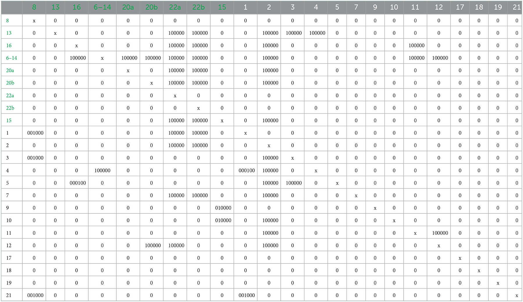
Table 2. DPM matrix applied to the BOM components (fasteners in green).
3.3. Case study
Coupling Design for Disassembly methodologies with cutting-edge technology such as Augmented Reality can offer remarkably efficient practical solutions. To understand this, it is enough to imagine a corporate department dedicated to the maintenance of mechanical assemblies such as motors, automatic packaging machines, pumping and plant systems (Liverani et al., 2010; de Marchi et al., 2013). Operators are usually asked to remove a number of components to clear a path to repair a specific target component internal to the product being serviced. Providing them with a drawing of an engine and the directions to follow to complete the job is often inefficient, as the complexity of the job is compounded by the complexity of having to understand the design of the product and the type of operations to be performed on it. Therefore, the idea is to show operators what they need to do by providing them with appropriate devices that can operate in augmented reality. The use of visors or Hololens is sufficient to meet this need. In fact, the ease of use of AR technology is such that even an application on a cell phone can be implemented without having to deal with large costs and timelines. Equipped with a viewer, operators can easily observe the components to be removed in the appropriate order and manner, without having to resort to the use of instruction booklets and technical drawings. At this point, the operator is simply called to copy what he observes in augmented reality.
There are several ways to approach the world of augmented reality. A widely available and easy-to-use online platform is Vuforia, a solution also considered in this paper for the purpose already described. Its main usefulness lies in the fact that thanks to Vuforia it is possible to define or draw a reference element (marker) for the product to be visualized in augmented reality in such a way that when the operator equipped with a visor observes that image, he will also be able to visualize the virtual model of the product on which he needs to proceed with the repair. Within Vuforia, it is therefore possible to import one's own drawing or image and turn it into a marker. Then the download of the package containing all the information about it is made available, to be imported into Unity, and the license code to be copied and pasted, again within Unity. One important thing to consider is that the marker must be graphically complex enough to allow recognition of numerous positioning elements for the AR model. A drawing with only a few lines is most likely not sufficient. An idea about the effectiveness of the image chosen as a marker is provided directly by the online application, with a rating given from one to five stars. In this case, the reference marker was a very simple drawing consisting of different lines and colors. Its implementation allows for a rating of 3 out of 5 stars on Vuforia. Although it is not optimal, it is sufficient to allow visualization of the condensate drain in augmented reality. Such a representation is shown in Figure 5. Having finished the procedure on Vuforia, the real application for the AR model is developed in Unity. By importing the virtual assembly of the analyzed product in obj or stl format, it can be colored by assigning particular display properties (opacity, reflections, roughness, and so on) to each element. The goal is to display each component of the assembly characterized by the material with which it was fabricated, and not just by its geometry (Osti et al., 2019). In Unity's “hierarchy” panel, it is therefore possible to make the assembly a child of the Image Target, so that starting the application will allow its display alongside the chosen image. The use of a QR Code is also sufficient for this purpose. With the help of Unity's timeline, a temporal movement can be imposed on each element of the system, in such a way as to produce a kind of AR movie in which the visual procedure to be followed by the operator is made clear and unambiguous. It is precisely in this step that the results obtained by applying Design for Disassembly methodologies and augmented reality meet. In fact, the animation to be imposed on the components of the virtual product model must follow the optimal sequence previously derived. For those who will view the model with the help of an appropriate viewer, every single step must be clear. Fasteners (screws, bolts, nuts, washers, and so on) will be the first components to come out. While this is happening in mock-up, the technician will have to operate on the physical model to be repaired until each step is completed. It becomes intuitable how much time such a procedure can save, as people learn as they work. There is no intuitively better approach than this in the current state of things. Excluding the possibility of a particularly dangerous process to be carried out by maintenance workers in one or more phases, it is then possible to train the staff and to complete the required industrial tasks at the same time without dividing the two phases temporally. This leads to a drastic reduction in the amount of time and cost to be invested in operator training by companies. In relation to the technical skills required by the people who will make use of this technology within corporate departments, it can easily be seen that no special adaptations are needed. The only initial difficulty might concern the use of the visor, through which the flow of information reaching the person's eyes is rather high (it is that of two realities in one). However, regarding the latter aspect, not much can be done; it is only required a sufficient amount of training on the part of the staff.
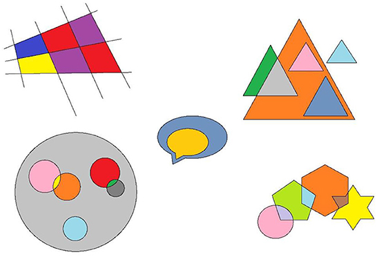
Figure 5. Representation of the marker used to locate the condensate drain in augmented reality.
Figure 6 shows an image of the proposed float condensate drain in augmented reality. Operators will be able to observe at the same time everything that belongs to the real world (the physical prototype to be assembled, the technical equipment needed to do so, the other operators, the working environment, and so on) and what comes from the virtual simulation built using augmented reality software such as Unity and Vuforia. At that point it is simply a matter of copying from the virtual into the real.
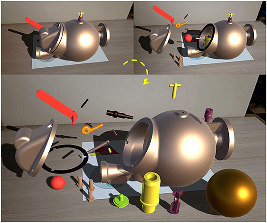
Figure 6. Different removal phases of the assembly components in augmented reality shown clockwise.
3.4. Timing analysis using augmented reality
To get feedback on the time gain associated with a potential use of this technology within a production department an idea might be to test it directly on people. In fact, it was planned to analyze the abilities of different people in performing the disassembly of the condensate drain under different conditions. Specifically, five people were asked to perform the complete disassembly without providing any indication of the functionality and composition of the product under consideration (the condensate drain). Another five people were provided with the drawing of the assembly to orient themselves on the location of the parts within it. Another five people, however, were asked to perform the complete disassembly of the product while visualizing in augmented reality the procedure to be followed (which component to remove and at what moment).
It is important to point out several aspects regarding this analysis. First of all, the total number of people involved is fifteen. This is because it would not have made sense to involve the same person in two different situations. Since the first time he gets to the complete disassembly of the product it follows that he is likely to remember the sequence he went through. The calculation of time applied on the same person but according to another mode would inevitably be affected. In addition, it was considered to involve people not necessarily learned in the context of mechanical design. This decision stems from the fact that in general even those who do not know the architecture of a product in detail can still attempt to take it apart and succeed. Finding a decrease in the average disassembly time by using an augmented reality application even on people who are not professionals undoubtedly lends value to this methodology. Moreover, such a situation is good for simulating the awkwardness that even a technician exhibits the first time he or she has to get his or her hands on a new product. Finally, it is necessary to describe in more detail how the experiment was performed. First of all, this is a purely virtual experiment. No physical prototypes or technical tools were used. The disassembly carried out by each person involved in the analysis was performed by them within the Unity interface, since in it the handling of objects (the virtual models of each component of the assembly) is easy and intuitive.
While for those who followed the disassembly in augmented reality it was only a matter of getting acquainted with the handling of the parts, in the other cases numerous nonsenses were recorded. Attempting to remove a component still secured with a screw or mistaking its removal direction were two common mistakes. In that case, the regulations required that the component be replaced in its original position and then proceed with a new removal attempt in a different direction, or of a different component. An example related to a conceptual error concerning the attempt to remove the wrong element is given in Figure 7.
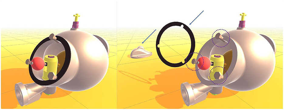
Figure 7. A case such as the removal of the lid and oil seal performed before the three-screw removal represents an example of errors detected in the course of the analysis.
At the end of the experiment, the results were listed in a matrix (Table 3).
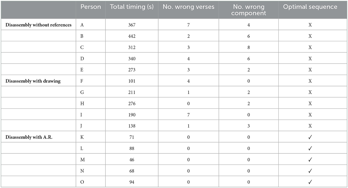
Table 3. Results from disassembly analysis.
As can be seen in that table, the times recorded on individuals who learned what to do through augmented reality are significantly lower than those who did not take advantage of any kind of help and those who made use of the assembly drawing. Even in the case of attempts to remove unremovable or incorrectly versed components, the number of errors in the AR case goes straight to zero for both items. It is interesting to note that in general the use of the product drawing alone also brings an important advantage, as it allows showing how many and which components not visible from the outset are present inside. In the case of Person F, the use of the drawing alone resulted in a final disassembly time on the order of those that employed augmented reality. However, interestingly, below 100 s were only the last (and all). Without the aid of any kind there were those who needed more than 300 s to complete the disassembly correctly and logically (person A, B, C, D). With the help of drawing no one took more than 300 s to finish. However, it is clear that those who made use of the drawing had to understand the architecture of the product. In the case under consideration, which is purely illustrative, the architecture of the condensate discharger is not considered to be too complex when compared to that of motors, fluid-driven machines such as turbines and compressors, electric motors, robots, and so on. However, it becomes rather intuitive that being able to complete the disassembly without having to understand how the product is internally structured is what leads to the greatest time savings. It is only through the effectiveness that a visual and intuitive method such as one making use of augmented reality can achieve that.
4. Conclusions
The purpose of the work aimed to demonstrate how using a powerful and unexplored technology such as augmented reality can bring great benefits to the present industrial reality. Operators dedicated to maintenance and disassembly can learn in a visual and particularly intuitive way what steps they need to follow to accomplish their tasks. A lack of technical skills to be attributed to manpower, the use of inadequate equipment, and an inability to understand the proper procedure for carrying out an industrial task constitute irrecoverable economic damage to the company. By now, the use of manuals that are time-consuming to consult and not always available is out of the question, considering the ever-tightening timelines to which employees of companies working on assembly lines or in maintenance departments are subjected. The fact that every company now possesses a digital model of the products it markets makes the application of DfD and AR rather quick and inexpensive. The application of the optimization methodologies proposed under DfD is absolutely worth considering for the future of companies and their ability to be competitive in the market. Combining them with augmented reality is the final step to take to elevate standard procedures to unprecedented levels of cutting-edge and technological advancement.
Data availability statement
The original contributions presented in the study are included in the article/supplementary material, further inquiries can be directed to the corresponding author.
Author contributions
Conceptualization, validation, and resources: LF and GD. Methodology: GD and MF. Formal analysis, investigation, writing—original draft preparation, and visualization: MF. Data curation and supervision: LF. Writing—review and editing: LF, GD, and MF. Project administration: GD. All authors have read and agreed to the published version of the manuscript.
Conflict of interest
The authors declare that the research was conducted in the absence of any commercial or financial relationships that could be construed as a potential conflict of interest.
Publisher's note
All claims expressed in this article are solely those of the authors and do not necessarily represent those of their affiliated organizations, or those of the publisher, the editors and the reviewers. Any product that may be evaluated in this article, or claim that may be made by its manufacturer, is not guaranteed or endorsed by the publisher.
References
Akinade, O. O., Oyedele, L. O., Ajayi, S. O., Bilal, M., Alaka, H. A., Owolabi, H. A., et al. (2017). Design for Deconstruction (DfD): critical success factors for diverting end-of-life waste from landfills. Waste Manag. 60, 3–13. doi: 10.1016/j.wasman.2016.08.017
Berg, L. P., Behdad, S., Vance, J. M., and Thurston, D. (2013). “Disassembly sequence evaluation using graph visualization and immersive computing technologies,” in Proceedings of the ASME Design Engineering Technical Conference (Berkeley, CA) 2, 1351–1359. doi: 10.1115/DETC2012-70388
Boothroyd, G., and Alting, L. (1992). Design for assembly and disassembly. CIRP Ann. Manuf. Technol. 41, 625–636. doi: 10.1016/S0007-8506(07)63249-1
Chang, M. M. L., Ong, S. K., and Nee, A. Y. C. (2017). AR-guided product disassembly for maintenance and remanufacturing. Procedia CIRP 61, 299–304. doi: 10.1016/j.procir.2016.11.194
Cong, L., Zhao, F., and Sutherland, J. W. (2017). Product redesign for improved value recovery via disassembly bottleneck identification and removal. Procedia CIRP 61, 81–86. doi: 10.1016/j.procir.2016.11.216
de Marchi, L., Ceruti, A., Marzani, A., and Liverani, A. (2013). Augmented reality to support on-field post-impact maintenance operations on thin structures. J. Sens. 2013, 1–10. doi: 10.1155/2013/619570
Eswaran, M., Gulivindala, A. K., Inkulu, A. K., and Raju Bahubalendruni, M. V. A. (2023). Augmented reality-based guidance in product assembly and maintenance/repair perspective: a state of the art review on challenges and opportunities. Expert Syst. Appl. 213, 118983. doi: 10.1016/j.eswa.2022.118983
Favi, C., Germani, M., Mandolini, M., and Marconi, M. (2012). “LeanDfd: a design for disassembly approach to evaluate the feasibility of different End-of-Life scenarios for industrial products,” in Leveraging Technology for a Sustainable World - Proceedings of the 19th CIRP Conference on Life Cycle Engineering (Berkeley, USA), 215−220. doi: 10.1007/978-3-642-29069-5_37
Favi, C., Germani, M., Mandolini, M., and Marconi, M. (2016). Includes knowledge of dismantling centers in the early design phase: a knowledge-based design for disassembly approach. Procedia CIRP 48, 401–406. doi: 10.1016/j.procir.2016.03.242
Haapala, K. R., Zhao, F., Camelio, J., Sutherland, J. W., Skerlos, S. J., Dornfeld, D. A., et al. (2013). A review of engineering research in sustainable manufacturing. J. Manuf. Sci. Eng. 135, 041013. doi: 10.1115/1.4024040
Harjula, T., Rapoza, B., Knight, W. A., and Boothroyd, G. (1996). Design for disassembly and the environment. CIRP Ann. 45, 109–114. doi: 10.1016/S0007-8506(07)63027-3
Liverani, A., Leali, F., and Pellicciari, M. (2010). Real-time 3D features reconstruction through monocular vision. Int. J. Interact. Des. Manuf. 4, 103–112. doi: 10.1007/s12008-010-0093-5
Lowe, G., and Bogue, R. (2007). Design for disassembly: a critical twenty-first century discipline. Assem. Autom. 27, 285–289. doi: 10.1108/01445150710827069
Osti, F., Ceruti, A., Liverani, A., and Caligiana, G. (2017). Semi-automatic design for disassembly strategy planning: an augmented reality approach. Procedia Manuf. 11, 1481–1488. doi: 10.1016/j.promfg.2017.07.279
Osti, F., Santi, G. M., and Caligiana, G. (2019). Real time shadow mapping for augmented reality photorealistic rendering. Appl. Sci. 9, 1–20. doi: 10.3390/app9112225
Papakostas, N., Pintzos, G., and Triantafyllou, C. (2015). Computer-aided design assessment of products for end of life separation and material handling. CIRP Ann. Manuf. Technol. 64, 185–188. doi: 10.1016/j.cirp.2015.04.023
Popoff, A., and Millet, D. (2017). Sustainable life cycle design using constraint satisfaction problems and quality function deployment. Procedia CIRP 61, 75–80. doi: 10.1016/j.procir.2016.11.147
Santi, G. M., Ceruti, A., Liverani, A., and Osti, F. (2021). Augmented reality in Industry 4.0 and future innovation programs. Technologies 9, 1–18. doi: 10.3390/technologies9020033
Smith, S. S., and Chen, W. H. (2011). Rule-based recursive selective disassembly sequence planning for green design. Adv. Eng. Inform. 25, 77–87. doi: 10.1016/j.aei.2010.03.002
Tao, F., Bi, L., Zuo, Y., and Nee, A. Y. C. (2018). Partial/parallel disassembly sequence planning for complex products. J. Manuf. Sci. Eng. Trans. ASME 140, 011016. doi: 10.1115/1.4037608
Umeda, Y., Miyaji, N., Shiraishi, Y., and Fukushige, S. (2015). Proposal of a design method for semi-destructive disassembly with split lines. CIRP Ann. Manuf. Technol. 64, 29–32. doi: 10.1016/j.cirp.2015.04.045
Yi, J., Yu, B., Du, L., Li, C., and Hu, D. (2007). Research on the selectable disassembly strategy of mechanical parts based on the generalized CAD model. Int. J. Adv. Manuf. Technol. 37, 599–604. doi: 10.1007/s00170-007-0990-3
Keywords: Design for Disassembly, augmented reality, CAD modeling, maintenance optimization, Industry 4.0
Citation: Frizziero L, Donnici G and Freddi M (2022) Design for Disassembly combined with augmented reality for optimization of maintenance processes. Front. Sustain. 3:1066448. doi: 10.3389/frsus.2022.1066448
Received: 10 October 2022; Accepted: 02 December 2022;
Published: 16 December 2022.
Edited by:
Claudio Favi, University of Parma, ItalyReviewed by:
Marta Rossi, Marche Polytechnic University, ItalyJeremy Rickli, Wayne State University, United States
Hoda Abuzied, The British University in Egypt, Egypt
Copyright © 2022 Frizziero, Donnici and Freddi. This is an open-access article distributed under the terms of the Creative Commons Attribution License (CC BY). The use, distribution or reproduction in other forums is permitted, provided the original author(s) and the copyright owner(s) are credited and that the original publication in this journal is cited, in accordance with accepted academic practice. No use, distribution or reproduction is permitted which does not comply with these terms.
*Correspondence: Marco Freddi,  bWFyY28uZnJlZGRpMkB1bmliby5pdA==