 Salvatore F. Cannone
 Andrea Lanzini
 Stefano Stendardo
95% of researchers rate our articles as excellent or good
Learn more about the work of our research integrity team to safeguard the quality of each article we publish.
Find out more
ORIGINAL RESEARCH article
Front. Sustain. , 21 October 2021
Sec. Circular Economy
Volume 2 - 2021 | https://doi.org/10.3389/frsus.2021.740105
This article is part of the Research Topic Circular Carbon Systems and Processes View all 8 articles
Coupling solar thermal energy with the hybrid TC/CG-ES (thermochemical/compressed gas energy storage) is a breakthrough option used to overcome the main challenge of solar energy, i.e., intermittent resource and low density. This paper proposes an innovative storage system that improves the competitiveness of solar thermal energy technologies compared to conventional fossil-based power plants, potentially leading to deep decarbonization of the energy and industrial sectors. This study uses thermochemical energy storage based on the calcium looping (CaL) process and takes advantage of a number of factors: high energy density (2 GJ/m3), absence of heat loss (seasonal storage), high operation temperature (high efficiency of the power plant), and use of cheap and environmentally friendly reactant feedstock (CaO/CaCO3). This work deals with the integration of the solar CaL storage system with an unconventional supercritical CO2 (s-CO2) Brayton cycle. We analyze different s-CO2 Brayton cycle layouts suitable for direct integration with the storage system. Energy integration via pinch analysis methodology is applied to the whole system to optimize the internal heat recovery and increase the efficiency of the system. A parametric study highlights how the integration of solar CaL with an intercooling Brayton cycle shows better results than the combination with the Rankine cycle that we investigated previously, resulting in net and global system efficiencies equal to 39.5 and 51.5%. Instead, the new calculated net and global system efficiencies are 44.4 and 57.0%, respectively, for TC-CG-ES coupled with the Brayton power cycle.
The main possible solutions to decouple CO2 emissions from economic growth are (i) switching to a low carbon economy, (ii) increasing system efficiency, and (iii) implementing carbon capture utilization and storage (CCUS) technologies to allow a gradual transition from fossil fuels to other more sustainable or renewable fuels. Conventional fuels produce a great quantity of greenhouse gas (GHG) during their combustion. In addition, they are also limited resources, which translates into a volatile market with daily price changes. Therefore, renewable energy is less harmful to the environment and ensures greater safety in the electricity grid. Solar energy is one of the most feasible energy sources among all renewable sources because it is low cost and potentially largely available (Islam et al., 2018).
The “Sun Belt” region (i.e., North Africa, the Mediterranean region, and vast areas of the United States) receives high yearly solar irradiance and specifically direct normal irradiance useful for concentrated solar power (CSP) plants (Wang, 2019). One of the most promising technologies is the solar tower power (STP) plant. STP plant consists of many sun-tracking mirrors (heliostats), which concentrate the solar irradiation onto an absorber, called a receiver, usually located atop a tower. The concentrated radiation is transformed into heat that is transferred by the heat transfer fluid and used to produce electricity. There are many different receiver technologies (e.g., gas, liquid, and solid particle receiver), which work with varying shapes of receiver and heat transfer fluid (Ho and Iverson, 2014).
Several large plants with a capacity between 100 and 200 MW are in operation (Teske et al., 2016). Among the plants constructed, the Ivanpah Solar Electric Generating System stands out for larger gross capacity (392 MW), located in California, USA (Islam et al., 2018).
Concentrated solar power strongly depends on weather conditions and, more specifically, on the availability of direct sunlight. Therefore, a cheap and efficient energy storage system is needed to fit the mismatch between discontinuous renewable energy supply and demand and to boost the capacity factor of CSP and solar thermal energy technologies (Denholm et al., 2010; McPherson et al., 2020).
A large number of thermal storage technologies have been developed for medium- and high-temperature CSP plants to increase the operational time of the CSP and its capacity factors and guarantee system continuity: (i) sensible thermal energy storage (STES), using high specific heat capacity materials such as molten salt systems or conventional direct steam storage (Aggarwal et al., 2021); (ii) phase change materials (PCMs) have high heat fusion and phase change temperature (Prieto and Cabeza, 2019); and (iii) thermochemical energy storage (TCES) (Pardo et al., 2014).
A conventional STES consists of two tanks of molten salt based on nitrate (60% NaNO3-40% KNO3) with hot and cold temperatures between 565 and 290°C and has a storage capacity of 0.731 GJ/m3 (ENEA, 2001). Latent energy storage has the advantage of providing heat at a constant temperature; carbonate salts (e.g., Li2CO3) have a high fusion temperature of 726°C with a storage density of 1.34 GJ/m3 (N. P. Siegel, 2012). However, both sensible and latent heat storage systems interact with the external environment, losing part of the stored heat. The stored hot salts can supply sufficient heat to produce steam and generate electricity for hours reaching power plant efficiency from 20 to 35% (Islam et al., 2018).
TCES storage avoids heat loss, producing stable chemical materials under favorable thermodynamic conditions. It uses heat provided by an external source to drive an endothermic reaction and stores them at ambient temperature. The heat necessary to produce electricity is supplied by an exothermic reaction between compounds whenever CSP cannot provide the energy required.
Unlike TES, electric energy storage can also store renewable energy and generate additional electricity when RES is not available. Compressed air energy storage (CAES) is another interesting solution. Air is compressed at the storage energy process and expanded into the Brayton cycle when energy is needed. If the air at high pressure (almost 40 bars) is heated to 470°C before the expansion, this system can reach an energy density of 0.39 MJ/kg (Giovannelli et al., 2020).
The present manuscript focuses on the integration of thermochemical energy storage (TCES) and compressed gas energy storage (CG-ES) in the CSP power plant. Thermochemical storage based on the CaL process has an energy density between two to five times higher than PCM and STES systems (3.2 GJ/m3), and the heat of reaction is discharged at a constant reaction temperature (lower than 895°C at atmospheric pressure) (Kyaw et al., 1996). Furthermore, this technology can be considered seasonal storage, unlike the others, used more as daily or weekly storage.
CaL is a cyclic chemical process that includes two reactions (Shimizu et al., 1999): (i) calcination of CaCO3 as reported in Equation 1 and (ii) carbonation of CaO as reported in Equation 2.
The CaL process is gaining considerable interest as a thermochemical energy storage process (Bailera et al., 2020; Karasavvas et al., 2020). As shown in the above equations, in the CaL process, calcination is the endothermic reaction, while carbonation is the exothermic one.
The calcination reaction of the spent sorbent occurs at a high temperature (≈900°C) (Stanmore and Gilot, 2005) with a CO2 partial pressure of 1 bar. Several strategies are used to reduce the calcination temperature of calcium carbonates, such as the dilution of CO2, easily detachable with steam or helium. Indeed, if we reduce the partial pressure of CO2, the temperature necessary to regenerate the spent sorbent, i.e., CaCO3, decreases (Stanmore and Gilot, 2005).
Calcium oxide is a mineral that can be easily obtained from abundant natural materials (e.g., limestone, dolomite); it is harmless toward the environment and humans, with several outlet markets for spent materials (e.g., iron, steel, and cement industries). Due to its wide availability, CaO has a low market price [9 €/ton dolomite (Ortiz et al., 2017)], and commercial limestone rock generally contains more than 90% of calcium carbonate (CaCO3).
Although naturally occurring Ca-based materials are attracting significant attention as CO2 acceptors for economic reasons, the rapid decay over cycles in their CO2 uptake capacity makes their use unsuitable. This loss of reversibility is due to the thermal sintering of CaO, resulting in a reduction of surface area and pore closure (Anthony, 2011). Thus, several strategies to avoid the fast decay of CO2 capture capacity have been proposed, such as thermal pretreatment of naturally occurring carbonates (Stendardo and Foscolo, 2009) and synthetic Ca-based sorbents by incorporating inert support material (Broda and Müller, 2014).
Many researchers have studied the CaL process as energy storage integrated with a different external source. Hanak and Manovic have compared the s-CO2 cycle and conventional steam cycle combined with CaL to capture CO2 from a coal-fired power plant. The CO2 was captured in the carbonator reactor operating at 650°C, while the CaCO3 produced was regenerated in a calciner at 900°C. As a result, the net thermal efficiencies for a CaL retrofit using the s-CO2 cycle and supercritical steam cycle are 31.6 and 30.6%, respectively (Hanak and Manovic, 2016). An extensive review of the state of the art on the integration of a CSP plant with the CaL system was written by Ortiz et al. (2019). Several integration schemes are summarized from the literature: (i) an open-air Brayton cycle, in which the air at the outlet of a carbonator reactor (direct cycle) is expanded directly in the main turbine, reaching a plant efficiency equal to 43.7% with a CaO conversion (X = 0.2) (Edwards and Materić, 2012); (ii) a closed CO2 Brayton cycle, in which the unreacted CO2, heated in the carbonator, is delivered in a gas turbine, achieving an efficiency between 44 and 46% with X = 0.5 (Alovisio et al., 2017); and (iii) an indirect recompression s-CO2 Brayton cycle analyzed by Ortiz et al. (2017) and Tesio et al. (2020) able to achieve an efficiency equal to 32 and 40.4%, respectively, with X = 0.5.
Nevertheless, the direct expansion of CO2 at the exit of the carbonator reactor is not recommended because it may contain solid particles that would damage the blades of the turbines downstream. In the last work, we have performed a conventional Rankine cycle integrated by a solar calciner to improve the efficiency of the system (Cannone et al., 2020). As a result, net electric efficiency and gross (electric and thermal) efficiency were estimated, respectively, equal to 39.5 and 51.5%.
This work has explored a novel power plant, integrating the CaL process to a closed s-CO2 Brayton cycle assisted directly by a solar calciner. The greatest novelty is given in the transformation of a plant usually used only for the production of electricity, into a trigeneration system. In fact, the CO2 produced in the calciner and stored in a tank is used to produce heat provided to a district heating network, while that taken from the high-pressure storage system is used to produce electricity and supply cold to a district cooling network. The use of a solar calciner reactor integrated with the optimized intercooling s-CO2 Brayton cycle allowed us to reach a net efficiency equal to 44.4% and a global system efficiency equal to 57.0%. The process configuration contains both the storage and power islands, and it is explained in Process Configuration Section. The methods and equations used in the optimization process are shown in Methods and Equations section. We have investigated four different configurations of the s-CO2 cycle (Modeling Approach of s-CO2 Brayton Cycle Section), and the best performing one was chosen in Results of the Parametric Analysis Applied to the Power Island Section. We have used the pinch analysis methodology explained in Pinch Analysis Applied to the CaL System Section to optimize the integration system (the results are shown in Results of the Pinch Analysis Applied to the Storage System section), and the sensitivity analysis, illustrated in large part of Methods and Equations section, explores the effects of main parameters on the plant performance (Results of the Parametric Analysis Applied to the Storage System and Results of the Parametric Analysis Applied to the Overall System sections).
This section describes the process configuration of the indirect integration between the CaL and s-CO2 Brayton cycle power plant schematized in Figure 1. Several heliostats collect solar radiation to beam down the central reflector and then into a solar calciner receiver. The solar calciner receiver is a solid particles fluidized bed operating in an anhydrous environment. The optical losses increase using a secondary mirror, but thermal losses drop down, and as a result, high temperature can be reached (T ≈ 950°C). With this configuration, the solar calciner receiver is located near the floor, reducing the problems of mechanical strength of the structure (Segal and Epstein, 1999; Chirone et al., 2013; Siegel and Ermanoski, 2013; Matsubara et al., 2014). In this reactor, solar energy is (i) gathered via decomposition of CaCO3 in CO2 and CaO and (ii) stored as their chemical potential. For simplicity, all the energy gathered by the CSP is stored by the CaL system, and therefore, only the hot CO2 outgoing the carbonator reactor provides heat to the power block. The fluctuations of solar energy stored in chemical products can be used to generate heat and electricity with zero CO2 emissions via the s-CO2 power cycle. As a result, the problem of dispatching and intermittency of renewable energy can be solved.
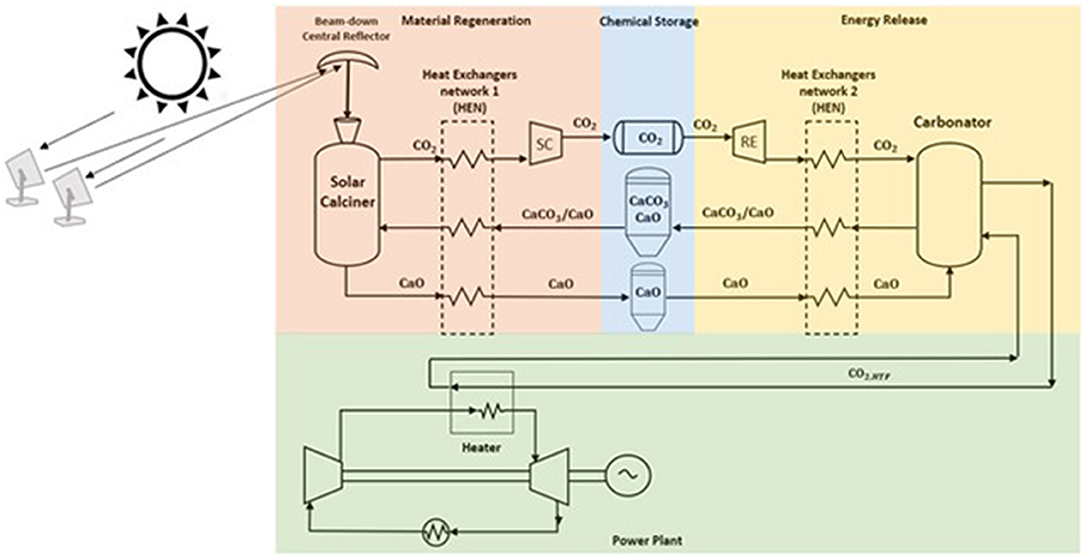
Figure 1. Integrated solar calcium looping (IS-CaL) with direct calcination reaction in the solar calciner. The spent material flows into the solar calciner, a solid particle fluidized bed reactor with CO2, to store solar energy through sorbent regeneration. The compounds, produced at high temperatures, provide heat to the spent sorbent in the heat exchanger network, and then they are stored at ambient temperature to avoid thermal losses. Regenerated sorbents are preheated in HEN2, and the exothermic reaction occurs in the carbonator reactor providing heat at high temperature to a power cycle.
The commercial software ChemCAD™ was used to model and simulate the optimized s-CO2 Brayton cycle, the CaL storage system, and their integration. This software is used to solve the mass and energy balances of the complex systems, provide an extensive database of chemical components, and simulate chemical reactions. A steady-state ChemCAD™ model was assembled. At the same time, the commercial EES software was used to resolve the equations of state and simulate the different Brayton cycle configurations.
The charging process takes place in the calciner reactor. Calcium carbonate and unreacted calcium oxide leaving the carbonator are stored at ambient conditions. When the solar calciner is fed, CaCO3 and CaO leaving the storage sites are preheated via a heat-exchanger network (HEN1) by the hot products (i.e., CaO, CO2) leaving the calciner. Here, the endothermic reaction occurs at high temperature (950°C) under a partial pressure of CO2 of approximately 1 bar utilizing solar energy input. The solar calciner is a fluidized bed where the fluidizing agent is a pure stream of CO2, and the solid bed is mainly composed of CaCO3 and CaO. The endothermic reaction decomposes the reactant in carbon dioxide and calcium oxide. The solid product is cooled down and stored at ambient temperature to avoid heat losses. CO2 stream provides heat to the reactants, and it is compressed via the storing compressor (SC) at supercritical conditions (75 bars) and directed to a storage tank at ambient temperature. Details of the SC component and the district heating network are provided in Supplementary Material Section 1.1.
CO2 stored at supercritical conditions passes through the recovery expander (RE), reducing its pressure until carbonator pressure. Details of the RE component and the district cooling network will be given in Supplementary Material Section 1.1. The hot products (CaCO3 and unreacted CaO) leaving the carbonator reactor preheat the reactants, coming from their storage sites, via a heat-exchanger network (HEN2), and are stored at ambient conditions. The preheated reactants are sent into the reactor, and the exothermic reaction releases the heat required to produce the hot transfer fluid (HTF) stream CO2, HTF feeding the power unit. The storage sites (i.e., CaO silo and CO2 tank) have been sized in order to keep power production continuous (see later for the details). Figure 1 illustrates the TC/CG-ES that comprises the (i) calciner, (ii) storing compressor with heat recovery (SC), (iii) turbo expander (RE) for cooling recovery, and (iv) carbonator. In this mechanical and chemical system, CO2 is used both as working and reacting fluid: it is compressed in SC, expanded in RE, and applied for storing and releasing the energy into the two main reactors.
During the discharging process, a hot stream (i.e., CO2,HTF) leaves the carbonator, providing power heat to the working fluid of the Brayton cycle, as shown in Figure 1.
The s-CO2 Brayton cycle is integrated into the STP, replacing the current water-steam Rankine cycle analyzed in our previous work (Cannone et al., 2020) and the air Brayton cycle (Bryner et al., 2016). The CO2 acts as heat transfer fluid and the working fluid as well. The use of supercritical CO2 allows us to pump a fluid that is in the incompressible fluid state, thus saving electric power. Supercritical CO2 has both the advantages of high density as liquid and can reach high temperatures as gases.
CO2 critical condition is 30.98°C and 7.38 MPa, and the fluid becomes more incompressible near this point (IEA and Woodhill, 2002). The compactness of the s-CO2 Brayton cycle is mainly due to the minimum system pressure set above 7.38 MPa compared to the minimum pressure of the Rankine cycle of a few kPa. Therefore, the fluid density is always high, and the volumetric flow rate is lower. The drawback is that the pressure ratio of the turbine is small, and a large amount of heat must be recovered from the hot gas at the outlet of the turbine.
Several s-CO2 Brayton cycle configurations have been proposed, such as simple recuperation cycle, intercooling cycle, reheating cycle, precompression cycle, recompression cycle, and preheating cycle (Ahn et al., 2015). Their performances are evaluated as a function of the turbine inlet temperature (TIT) and optimizing other cycle parameters such as flow ratio of the separator or the turbine inlet pressure, usually setting at 250 bars (Binotti et al., 2017).
The s-CO2 Brayton cycle mainly consists of three components: heat exchanger, compressor, and turbine. The different numbers of those components, the different ways to connect theme, and the number of split and reconnection produce several cycle configurations. Two types of heat exchangers are used:
– One exchanges energy between the working fluid and an external heat hot/cold source.
– The other exchanges energy between hot and cold streams of the working fluid, and they are called recovery heat exchangers.
The first heat exchanger consists of a precooler, intercooler, heater, and possible reheater. The use of a reheater is avoided to get a more compact power unit. Contrariwise, in the precooler and intercooler, the working fluid rejects heat to the sink to obtain a specified compressor inlet temperature.
The recovery heat exchangers are critical. They are essential for achieving high system performance due to the small pressure ratio and larger outlet turbine temperature. However, attention must be paid because the two fluids often reach pinch-point temperatures.
Each component works at a steady-state condition and only thermodynamic equilibrium has been considered. The Soave–Redlich–Kwong (SRK) equation of state is used in both the K-values model and enthalpy model. We have neglected pressure and heat losses into each component, except for the carbonator reactor, in which about 1.5% of the heat produced by the exothermic reaction is lost. The carbonator and calciner are modeled as Gibbs reactors in which chemical and phase equilibrium through the free energy minimization at the operating temperature is reached.
We have assumed a complete regeneration of calcium carbonate in the solar calciner. In contrast, the sorbent is supposed to not achieve a complete conversion of CaO into CaCO3 (X < 100%) due to the diffusional resistances during carbonation. In addition, we supposed that the CaO sorbent deactivates at a large number of carbonation/calcination cycles. The CaO conversion is set at 70% (Chen et al., 2012), and the make-up flow is considered negligible, as reported elsewhere (Cannone et al., 2020).
In this work, we do not want to design the component of the system aimed at economic analysis, but we want to evaluate the thermodynamic efficiency of the optimized system. Therefore, we have assumed constant the heat required by the power block; instead, the solar multiple (i.e., the ratio of the solar thermal power to the power block design thermal input) varies to completely regenerate the material. Both Brayton cycles and CaL systems were simulated through several components such as reactors (carbonator and calciner), flow mix and splitter, turbines, compressors, pumps, and heat exchangers (e.g., solid–solid, gas–solid, gas–liquid, and gas–gas). In the model, each counterflow heat recovery exchanger heats up to a minimum temperature difference of 20°C.
This section aims to present a systematic performance comparison of s-CO2 Brayton cycles with different layouts. Four cycle layouts (simple regeneration, recompression cycle, partial cooling cycle, intercooling cycle) are considered integrated into the CaL solar power plant and are illustrated in Figure 2.
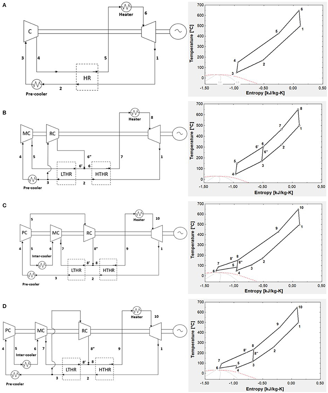
Figure 2. (A) Simple regeneration s-CO2 Brayton cycle; (B) recompression s-CO2 Brayton cycle; (C) partial cooling s-CO2 Brayton cycle; and (D) intercooling s-CO2 Brayton cycle. The corresponding T–s diagrams are shown on the right side.
The simple s-CO2 Brayton cycle was very inefficient because a large amount of heat could not be recovered and lost due to high outlet turbine pressure. Therefore, a first simple regeneration (5) was adopted (Figure 2A). Nonetheless, the significant difference in the heat capacity between high-pressure and low-pressure streams causes a limited recovery due to the temperature pinch-point problem.
The pinch-point problem mentioned above was avoided through the recompression cycle configuration in Figure 2B. Heat recovery was divided into low-temperature heat recovery (LTHR) and high-temperature heat recovery (HTHR). The recompression Brayton cycle reduces the mass flow rate of the high-pressure stream in the LTHR by splitting the low-pressure stream in two fluids. One stream flows onto the precooler and is pressurized onto the main compressor (MC). The second stream enters the recompressor (RC) at a higher temperature than usual, is compressed until the turbine pressure design, and mixes with the first stream at the inlet of the HTHR. The recompressor is less efficient because the inlet fluid is hot.
Figure 2C illustrates the partial cooling s-CO2 Brayton cycle and the T–s diagram, respectively. Conversely, to the previous configuration, in this cycle, an intercooling is added. Usually, intercooling is used to reduce the compression work of the cycle. The compression is divided into two stages by the intercooler. At first, all the low-pressure exhaust stream is cooled in the precooler and then enters the low-pressure compressor [precompressor (PC)], where it is compressed at an intermediate pressure.
At the exit of the PC, the flow is split. One stream flows into the intercooler and main compressor, the other flows directly into the RC. The electricity consumed by the RC is lower than the cycle in Figure 2B because the fluid is preliminarily cooled in the precooler. The presence of the intercooler also reduces the compression work of the MC.
The last cycle investigated is the intercooling s-CO2 Brayton cycle. In this configuration, the precooler unit is after the split located downstream LTHR. As shown in Figure 2D, the RC receives a relatively hot fluid (point 3 in the T–s diagram) and operates at the same pressure ratio of the turbine.
We have used four key parameters to optimize each cycle: TIT, compressor inlet temperature (CIT), split ratio (SR), and the ratio of pressure ration (RPR).
The RPR is a parameter used to evaluate the intermediate pressure of partial cooling and intercooling s-CO2 Brayton cycles. The RPR is defined as:
The SR is the simple ratio between the mass flow rate into the central compressor (ṁMC) over the total mass flow rate of the cycle (ṁ).
The cycle efficiency is the objective function to maximize, and it is calculated in the following equation. Wnet is the net power of the plant, while Φh is the heat power provided by the CaL storage system.
The main parameters used for efficiency evaluation and parametric analysis performance are listed in Supplementary Table 1. The analysis was performed at steady-state conditions, neglecting pressure and heat loss in all system components. We have performed the golden section method (Lindfield et al., 2012) as a direct optimization process. The objective function is iteratively calculated for various values of the independent variables.
All of the heat exchangers in the power cycle (i.e., heater, high- and low-temperature heat recuperators) are considered counterflow heat exchangers. The general thermal power balance equation for each heat exchanger and the electrical power equation for both compressors and turbine are calculated by:
In Equation 6, Φi is the thermal power exchanged; ṁh and ṁc are the mass flow rates of hot and cold streams, respectively; hh,in,i and hh,out,i are the enthalpy of the hot fluid at the inlet and outlet states, respectively; and hc,in,i and hc,out,i are the enthalpy of the cold fluid at the inlet and outlet states of the heat exchanger, respectively. On the contrary, in Equation 7, the term Wi represents the electrical power generated in the turbine (if Wi > 0) or required in the compressors (if Wi < 0), ṁ is the mass flow rate into the component, while hin,i and hout,i are the enthalpy of the fluid at the inlet and outlet states of the compressor or turbine, respectively.
The net power of the plant (Wnet) is expressed by Equation 8, while the mixing process of s-CO2 at stage 6 for the recompression cycle (see Figure 2B) and stage 8 for both partial cooling and intercooling cycles (see Figures 2C,D, respectively) are shown in Equation 9.
We have conducted the storage tank volume dimensioning starting from the balance of the molar flow rate in both main reactors, as shown in Figure 3.
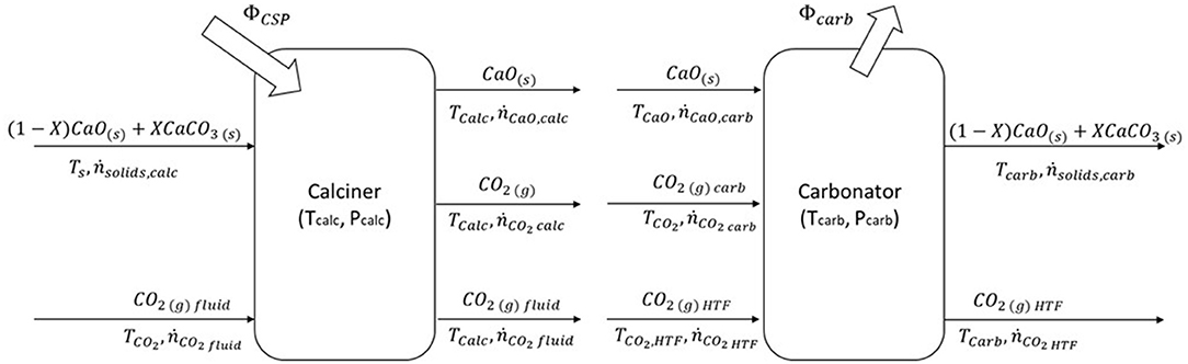
Figure 3. Molar and energy balance of the calcium looping process. On the left side, in the calciner, solar energy is collected and stored in chemical compounds; on the other side, CaO and CO2 react into the carbonator reactor. The heat of the exothermic reaction is transported by the CO2 used as HTF to the power block. Adapted with permission from Cannone et al. (2020). Copyright 2021 American Chemical Society.
During the storage process, the solid stream (ṅsolidscalc) composed of calcium carbonate (ṅCaCO3 calc) and unreacted calcium oxide (ṅCaO,unr, calc) enters into the calciner reactor. A solar calciner is a fluidized bed reactor in an anhydrous environment (ṅCO2 fluid is the fluidizing agent) at 950°C and 1 bar. Calcium carbonate is decomposed through endothermic reaction, driven by solar energy, in calcium oxide (ṅCaOcalc) and carbon dioxide (ṅCO2 calc). The two products of the reaction are cooled and stored at ambient temperature, while CO2 is pressurized until the supercritical condition (75 bars).
On the other side, during energy release, the two reactants are sent to the carbonator reactor. The carbonator reactor works at 720°C and 2 bars, and it is fluidized by carbon dioxide. Carbon dioxide (ṅCO2 HTF) has two functions: it fluidizes the reactor and transfers heat to the power block. In the carbonator reactor, the calcium oxide (ṅCaOcarb) and carbon dioxide (ṅCO2 carb) react, releasing heat at high temperatures. Part of calcium oxide does not react due to the behavior of the material discussed in the previous section. A stream of solids (ṅsolidscarb) exits from the carbonator reactor and, after cooling process, is sent to storage. The solids stream is composed of calcium carbonate and unreacted calcium oxide (ṅCaO,unr).
The main features of the material are the complete regeneration of the spent sorbent via calcination reaction and, otherwise, the partial uptake of CO2 along with the carbonation reaction. Therefore, the most critical parameter is the average CaO conversion (X) in CaCO3 in the carbonator during heat release. This parameter quantifies the amount of calcium oxide which reacts with CO2 during carbonation reaction and is defined in Equation 14.
The molar balance around the storage system has been considering a full day. Indeed, the carbonator reactor works every day for a 24-h span providing the heat required to the power plant. Instead, the calciner reactor works during sunlight considered for 8 h a day, and all the spent material has to be regenerated, as shown in Equation 15.
The storage volumes are computed starting from the molar flow rate enough to drive the carbonation reaction when solar energy is not available, and they are calculated with the following equation:
Where:
– V is the volume storage tanks (m3),
– ṅ is the molar flow rate (kmol/s),
– MM is the molar mass expressed in (kg/kmol),
– ρ is the density (kg/m3),
– dt is the time defined between 0 and 16 h corresponding on daytime without sunlight, and
– j is one of the following streams: solids leaving the carbonator, calcium oxide, and carbon dioxide both leaving the calciner.
The first law of thermodynamics is applied in each reactor, paying attention to the chemical reaction. At first, it is necessary to define the extent of reaction in Equation 17, which represents the completion degree of reaction (e.g., ε = 1, the reactants react completely, while ε = 0, if the reaction does not occur).
Where:
– ε is the extent of reaction [mol],
– νi is the stoichiometric coefficient of component i (νi > 0 for products, νi < 0 for reactants, and νi = 0 for inerts),
– ni,out − ni,in is the molar of component i that reacts in the reactor, and
– i is the compound between calcium carbonate, calcium oxide, and carbon dioxide.
The energy balances of both reactors are summarized in the following equations for the calciner reactor (Equations 18, 19) and carbonator reactor (Equations 20, 21).
The heat of the reaction function of temperature is defined as follows:
Figure 3 illustrates the molar and energy balances of the CaL system.
In addition, we have analyzed the influence of the key performance indicators (KPIs) on the efficiency of the system to set up the best operating conditions. The KPIs considered for the storage system are the carbonator temperature, carbonator pressure, and CaO conversion.
Several efficiencies focused on the storage system are defined below to compare its performance at different values of KPI. The three efficiencies move from considering the simplest thermal energy to the total energy produced and required by the CaL storage system, including mechanical energies and energies provided to the district network.
– The thermal storage efficiency (TSE) is focused only on CaL storage. It is defined as the thermal energy released by carbonation reaction over the energy input to drive the calcination reaction over a 24-h full day. Thermal storage efficiency does not consider the mechanical power to store the carbon dioxide at high pressure and expand it to carbonator pressure.
– The storage efficiency (SE) considers the thermochemical/compressed gas energy storage efficiency. Therefore, it is defined as the ratio between the heat released by carbonation reaction plus the expansion work of the CO2 stored at high pressure to the heat stored in solar calciner plus the compression work to save the CO2 produced by calcination reaction over 24 h.
– The storage and recovery efficiency (SRE) considers the whole energy parameter of the storage system, including the energy to DCN and DHN and the power required to pump the cooling fluid into the storage side over a 24-h day.
The pinch analysis was performed to optimize the heat exchangers network of the solar calcium looping integrated with the s-CO2 power plant. As a result, we have the external supply of heat and cold, and therefore, we have minimized the mass flow rate of the reactants required to preheat themselves and heat the working fluid of the power plant. A network of heat exchangers needs to be built.
The optimization of the energy storage side can be conducted separately from the optimization of energy release because the two sides are separated physically and temporally using storage components. Silos for solids compound and the pressurized tank of CO2 compose the storage area placed between the two main reactors.
At the starting point, we have identified all the components of each subsystem and the related streams which flow through each component. The energy storage side is composed of the calciner reactor and the storing compression (SC). In contrast, the energy release site contains the carbonator reactor and the RE, as shown in Figure 1.
In the second step, all the technical constraints and the boundary conditions are defined. There are two technical constraints: (i) second law of thermodynamics and (ii) minimum temperature difference between two fluids, set at 20°C. In contrast, the boundary conditions are (i) environment temperature, (ii) pressure and temperature of the reactors, (iii) temperature of the containers, (iv) pressure of the CO2 at the inlet of the storage tank, (v) pressure of the CO2 at the outlet of the RE, and (vi) temperature of the HTF coming out from the carbonator reactor.
The third step of this methodology involves calculating the external maximum heat and cold required from the system. In this way, we can evaluate the composite curves for the cold and hot fluids. Initially, both curves are started at zero abscissae. For the constraint of the second law, the cold fluid curve must always be below that of the hot fluid. The cold fluid curve is translated horizontally until the difference of minimum temperature set before will be obtained to make the result acceptable. As a result, the minimum energy requirement will be evaluated, and the heat exchanger network can be designed. The configuration of HEN, the phase change fluids, and the chemical reactions were treated following the methodology described in Verda and Guelpa (2015).
Three different efficiencies are defined to compare the performance of the system with others simulated in the previous manuscript (Cannone et al., 2020):
– The integrated efficiency (IE) is calculated as the ratio between the energy produced by the power plant and the solar energy input into the calciner reactor. This efficiency links the main input and output of the whole system directly over 24 h.
– The net efficiency (NE) also considers the power consumed or produced by the compression and expansion of CO2, respectively. Indeed, the CaL system can be seen as a mix of chemical storage (i.e., CaO and CO2 production) and CGES (compressed gas energy storage).
– The global efficiency (GE) considers the whole energy input and output of the system, including the heat at low enthalpy recovered by the district cooling and heating network.
The main objective of this section is to show the best-performing cycle among the four mentioned options before that will be integrated into the CaL-STP system.
Figure 4 shows the effect of the split ratio on the cycle efficiency. The simple regeneration cycle does not depend on the SR, but it is reported in the graph to compare all the cycle efficiency. While the intercooling cycle and recompression cycle are strongly depending on SR, the efficiency of the partial cooling cycle changes slowly, reaching the peak value (ηcycle = 45.2%) with SR equal to 0.6, about 4 points percentage higher than the minimum value. This behavior is mainly attributed to the cooling, the total mass flow rate at the inlet of the precompressor. It reduces the power consumed to boost the working fluid at an intermediate pressure.
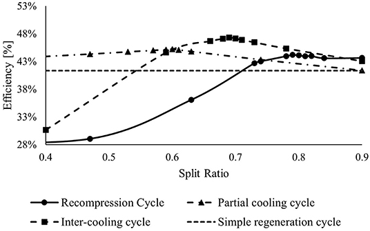
Figure 4. Effect of the split ratio on cycle efficiency keeping constant the other two variables (RPR and TIT).
The efficiencies of the recompression and intercooling cycles change mostly at different SR values. Increasing the SR, both cycles reach a peak and, after that, decrease slowly. The maximum efficiency is achieved by the intercooling cycle arriving at ηcycle = 47.2%.
Keeping constant the SR values that maximize the respective cycles, the intermediate pressure was investigated in Figure 5. At fixed maximum and minimum pressures, the RPR changes with different amounts of medium pressure. Only intercooling and partial cooling cycles present a precompressor unit, and therefore, only these two efficiencies can improve.
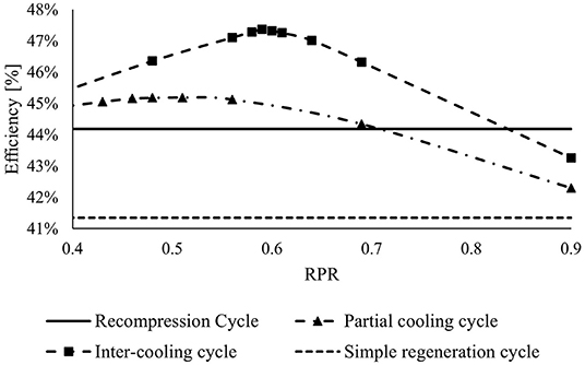
Figure 5. Effect of the RPR and therefore of intermediate pressure on cycle efficiency.
The maximum efficiency of intercooling and partial cooling cycles showed RPR equal to 0.59 and 0.51, achieving the peaking efficiency equivalent to 47.4 and 45.2%, respectively.
The last key parameters evaluated were the turbine inlet temperature (see Supplementary Figure 2) and the compressor inlet temperature (see Supplementary Figure 3).
The choice of a renewable source at high temperature and a heat transfer fluid that allows reaching even higher temperatures will permit higher efficiencies. The CaL process can provide heat at a higher temperature. Therefore, the intercooling s-CO2 Brayton cycle is chosen as the best cycle for the system integration working at 700°C, that is the maximum temperature achievable, and with a compressor inlet temperature set at 50°C, due to the general scarcity of water and scorching weather in the areas where it can be installed. The best efficiency achieved is 49.4%.
The calciner reactor operates at 950°C and 1 bar, while the carbonator reactor is set up at 720°C and 2 bars. The temperature of the carbonator reactor was imposed at 20°C higher than the maximum temperature of the power cycle to reduce exergy loss, mechanical stress of the material, and power heat provided to preheat the streams at the inlet of the carbonator reactor. Instead, the pressure of the carbonator was chosen to overcome pressure drop into each component in an original configuration. The CaO conversion X was set at 70% (Chen et al., 2012). Successively, a parametric analysis was carried out to evaluate the best-operating conditions. The principal process parameters and the detailed analysis are summarized in Supplementary Material Section 1.4.
Figure 6 describes the heat exchanger network resulting from the pinch analysis applied on the carbonator side. The heat transfer fluid leaving the carbonator reactor (1) provides 663.3 MW into HEA to feed the power block, heating the fluid (3) until 700°C. The hot solids stream warms the whole CO2 (6) until maximum temperature is achieved (545°C), and then, it was divided into two streams. The first substream provides heat both to (i) calcium oxide (7) in HEC (146.5 MW), reaching 516°C, and (ii) CO2 (4) via HED (36.7 MW) getting at maximum temperature before the recovery expander unit (44°C), while substream (2) is cooled down to 40°C. The remaining substream is directed to HEE, exchanging 90 MW with the stoichiometric CO2 at carbonator pressure (5) and sent to the storage tank at 27°C. The heat required by the reactants entering the carbonator (i.e., CaO at 516°C and CO2 at 545°C) to achieve the carbonator reactor temperature (720°C) is provided by the heat released by the exothermic reaction of carbonation, i.e., 666 MW.
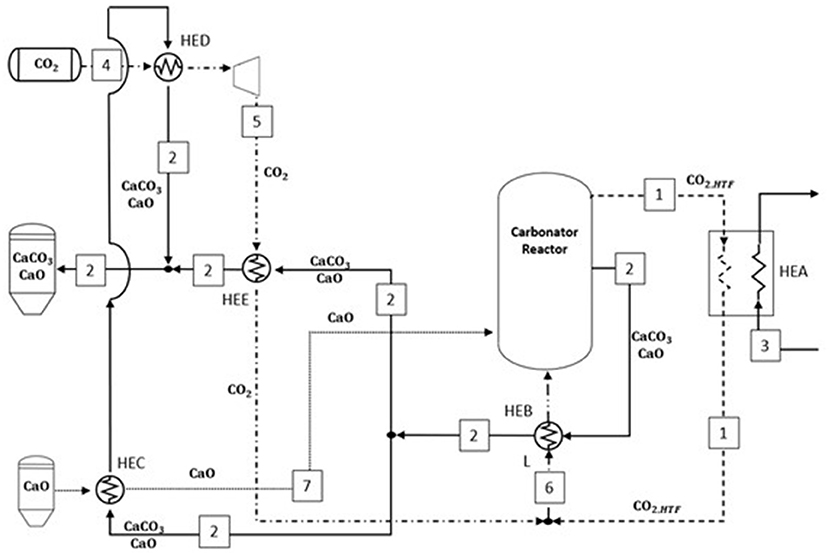
Figure 6. Minimum energy consumption network inferred from the pinch analysis on the carbonator side. The plant configuration results from the pinch analysis optimization.
The optimized heat exchanger network synthesized from pinch analysis in the heat storage section is reported in Figure 7. According to the pinch point, the only cold fluid (4) at ambient temperature is split into two streams; the first one passes through the HEA, receiving 17.8 MW from the CO2 and reaching cold pinch point temperature. At the same time, the second substream is heated up into HEB (i.e., 33.6 MW) from the compressed CO2 entering the storage tank. After these heat exchangers, the two solid streams are mixed at 50°C. The solid stream is split again into two streams. In HEC and HED, the hot calcium oxide and carbon dioxide leaving the solar calciner reactor provide 790 and 522 MW to the solids streams until the same exit temperature of 815°C. The remaining sensible heat (231 MW) and the heat required for endothermic reaction (1,933 MW) are provided by the solar calciner.
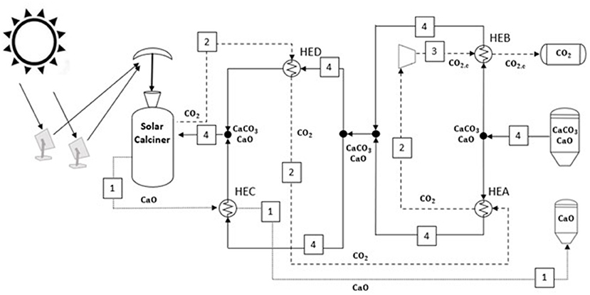
Figure 7. Minimum energy consumption network in the solar energy storage side. The plant configuration results from the pinch analysis optimization.
The proposed system configuration shown in Figures 6, 7 is the outcome of the pinch analysis explained in the previous section. This method maximizes the internal heat recovery, reducing the solar energy required by the power plant at nominal operating conditions.
We have performed the parametric analysis to find the best operational conditions of the carbonator reactor over selected parameters. The first analysis takes into account the effect of carbonator pressure on the efficiency of the storage system (see Figure 8).
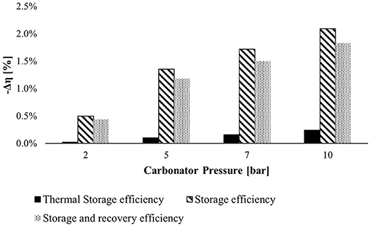
Figure 8. The negative efficiency variation at various carbonator pressures with respect to efficiency computed at 1.2 bar. The efficiencies decrease, increasing the carbonator pressure.
The bar chart above illustrates the TSE, SE, and SRE variation in absolute values at different carbonator pressures concerning the reference efficiencies calculated at 1.2 bar. The carbonator pressure affects the SE more because, increasing the carbonator pressure, the expansion work of stored CO2 drops down. The best choice should be selecting the reference pressure, but a carbonator pressure of 2 bars was chosen to avoid potential backflow (pressure drops in each component) in a real plant.
The second investigated KPI is the temperature of the carbonator reactor, and the results are shown in Figure 9. This parameter controls the system efficiencies robustly. Increasing the temperature of the carbonator reactor, the mechanical power recovered by CO2 expansion increases but not enough to counter the lowering heat of carbonation reaction. For this reason, the carbonator reactor works at 720°C.
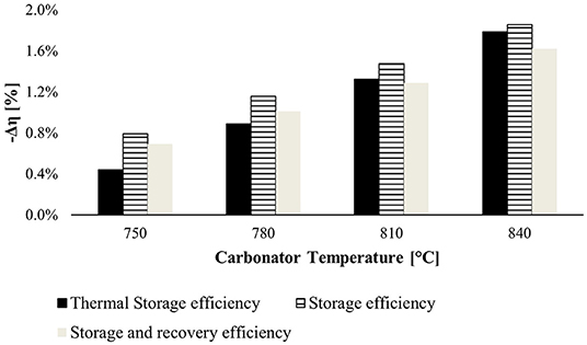
Figure 9. Negative variation efficiency at different temperatures of the carbonator reactor. The reference efficiencies are computed at 720°C (minimum temperature of the carbonator reactor to provide heat to the power block).
The CaO conversion (X) is the last KPI considered in this section. At different values of X, the heat of reaction in the carbonator reactor (670 MW) and the solar calciner (−1,933.4 MW) remains constant. This happens only by increasing the mass flow rate of the reactants so that the CaO converted in CaCO3 and vice versa is kept constant. Furthermore, the sensible heat to reach the operational temperature of the two reactors varies, as shown in Figure 10. As a result, the power heat required from CSP increases as well as the solar multiple between 3.2 and 3.4. On the contrary, the power heat available in the carbonator reactor as heat reaction drops down at low values of CaO conversion due to the increased sensible heat required to reach the temperature of the reactor with more reactants in the reactors. Figure 10B describes the behavior of the carbonator side. The heat exchanger network resulting from the pinch analysis was optimized for different CaO conversions. As a result, the split ratio of stream 2 (see Figure 6) sent to the HEE decreases at lower values of X. With a CaO conversion lower than 46%, the thermal power available is less than the power heat required by the Brayton cycle (663 MW). Therefore, to maintain the same electricity generation, (i) a new sorbent with a higher CO2 uptake capacity has to be used in the system; (ii) we can increase the mass flow rate of the reactants which flow into the carbonator reactor (i.e., CaO and CO2) working at fewer hours per day due to higher consumption of the stored material; (iii) otherwise, the TIT can be decreased along with the power generation and the efficiency of the intercooling s-CO2 Brayton cycle.
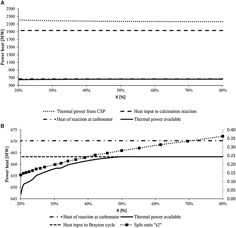
Figure 10. Thermal power heat of the main reactors at varying CaO conversions. (A) The increased sensible heat provided by CSP is highlighted. (B) The heat supplied to the Brayton cycle (small dotted line) and the heat of reaction (dotted-point line) are fixed, while the heat provided by the storage system (full line) changes.
Figure 11 shows the daily storage volume influenced by CaO conversion. The solid storage volume sharply decreases at high values of CaO conversion. The daily storage volume of solids (CaCO3 and CaO) produced by a carbonation reaction at X = 30% is 75% higher than the ones provided at X = 70%. On the contrary, the mass flow rate of CO2 directed to the carbonator reactor does not change, and therefore, the carbon dioxide storage volume is always the same .
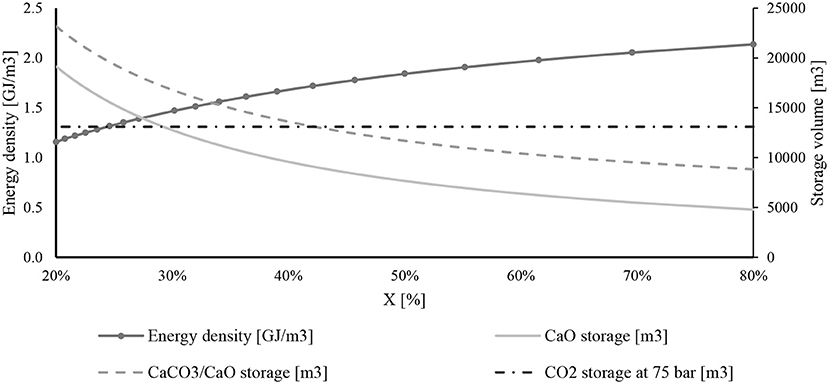
Figure 11. Daily storage volume of chemical compounds and energy density with the change of CaO conversion.
The same figure explains the energy density at different CaO conversions. Energy density is an important parameter useful for comparing different storage systems. It is defined as the ratio between the power heat available from the carbonator reactor and the storage volume of the two reactants.
The energy density rises when the CaO conversion goes up, starting from 1.1 to 2.1 GJ/m3.
Finally, Figure 12 reports the values of TSE, SE, and SRE with the change of CaO conversion. The efficiencies increase when X rises, reaching approximately a plateau at X = 70% achieving 87.3, 91.9, and 99.9%, respectively, for SE, TSE, and SRE. The SRE reaches the highest value because it considers heat at low temperatures exchanged with the district heating and cooling network.
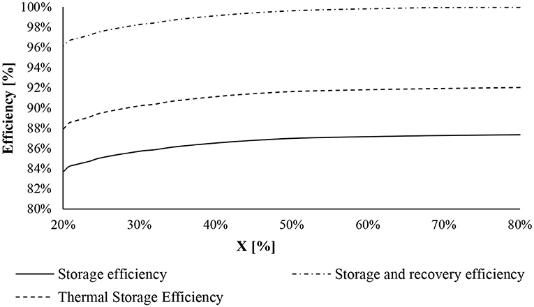
Figure 12. Efficiencies of the CaL storage system at a different value of CaO conversion: storage efficiency (full line), thermal storage efficiency (dotted line), and storage and recovery efficiency (dotted-point line).
The solar CaL storage system was integrated with the 320-MW intercooling s-CO2 power plant. As shown in the previous section, the s-CO2 Brayton cycle has an efficiency equal to 49.4% when it works at the condition summarized in Supplementary Table 6.
The heat required by the power plant is provided by the heat transfer fluid heated during exothermic reaction into the carbonator reactor. The ambient temperature is set at 20°C, but the s-CO2 is cooled until 50°C into the air cooler, considering seasonal temperature variation. Into the HTHR and LTHR, the minimum temperature difference was set at 20°C. Besides, the non-pressure drop was assumed into each heat exchanger.
The proposed system layout, as formulated in Figure 13, can operate in two different main configurations. The solar energy is collected from the field of heliostats and is reflected by the beam down the central reflector to the solar calciner. The accumulated energy can be (i) used directly to generate electricity and/or (ii) stored through the direct CaL process. In this paper, we have studied only electricity production by the CaL storage system.
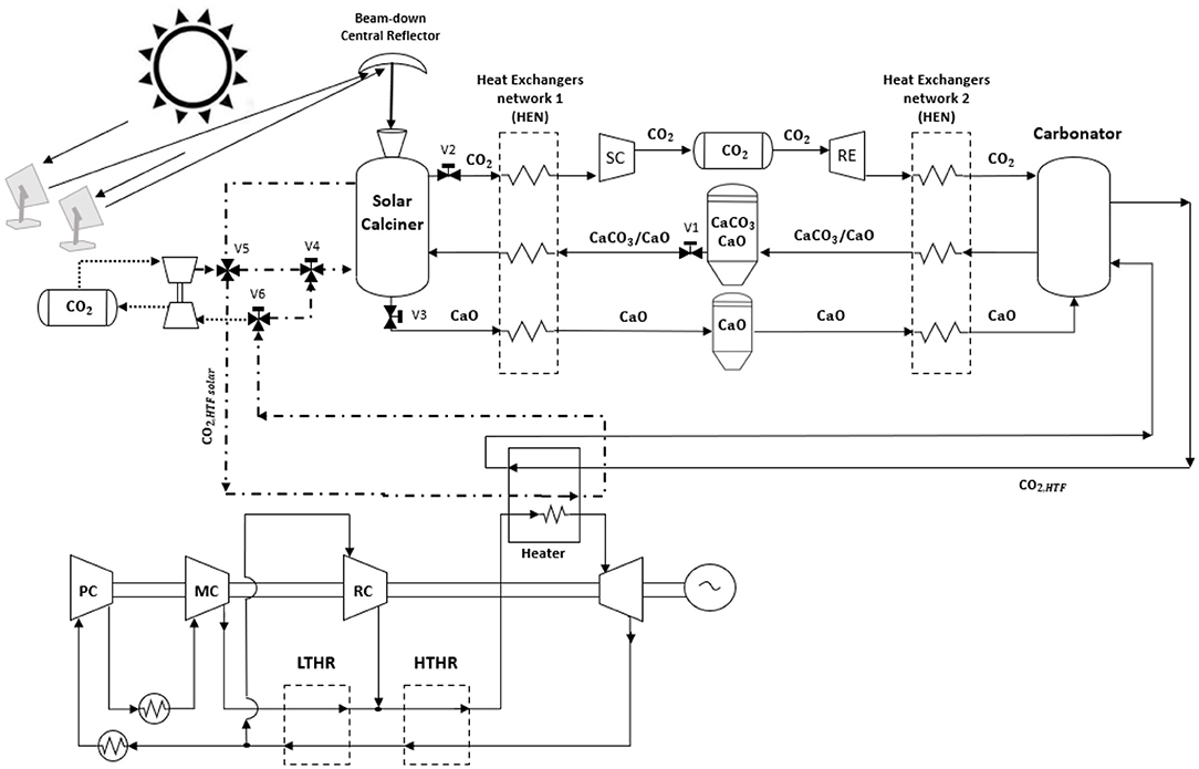
Figure 13. Thermochemical/compressed gas energy storage (TC/CG-ES) coupled with an unconventional intercooling s-CO2 Brayton cycle. During sunlight, the excess of harvested solar energy is stored in chemical compounds (i.e., carbon dioxide and calcium oxide) into the solar calciner. During the discharge process, the exothermic reaction provides heat to the s-CO2 Brayton cycle, while the products of the reaction (i.e., calcium carbonate and unreacted calcium oxide) are stored at ambient conditions.
In this work, we have integrated the solar CaL storage system with the intercooling s-CO2 Brayton cycle. The CaL storage system allows the working fluid of power plants to achieve high turbine inlet temperature. With the high pressure of working fluid in the power plant (250 bars), electricity is produced at higher efficiency.
Figure 14 reports the three efficiencies defined above at different values of CaO conversion. The efficiencies IE, NE, and GE increase with the increase of CaO conversion achieving 45.4, 44.4, and 57.1%, respectively. If we are not interested in recovery heat at low temperatures, the net efficiency can increase if air at 20°C flows both in intercooling and interheating components.
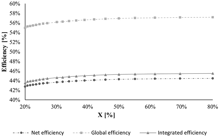
Figure 14. Efficiencies of the TC/CG-ES integrated with an intercooling s-CO2 power cycle.
All the electrical and thermal power duties produced and consumed by the various components and the plant efficiencies at a fixed CaO conversion value set at 0.7 are summarized in Supplementary Table 7.
The parametric analysis applied in our integrated system suggests the main operation conditions for both the power plant and the storage system. As shown in Figures 8, 9, the best operating conditions of the carbonator reactor are low pressure (P = 2 bars) and low temperature (T = 720°C), and therefore, the turbine inlet temperature was set at 700°C. We can explain these results because when pressure and temperature go up, the heat of reaction produced into the carbonator reactor decreases.
One of the important system variables is CaO conversion. The efficiencies of the system, when the heat exchanger networks are optimized, do not change a lot at different CaO conversion factors. On the contrary, with X lower than 46%, we need to reduce the electrical power produced because the heat provided to the Brayton cycle is not enough to work at nominal condition (see Figure 10B).
The most sensitive KPI is energy density. Indeed, decreasing CaO conversion, the size of the storage increases a lot, and therefore, as shown in Figure 11, the energy density of the system goes down.
The work done highlights the benefit of the trigeneration system model. Figure 15 illustrates the comparison between the net and global efficiencies resulted by our model, to the other presented in the literature. We can observe that the net efficiency of our plant is always higher than the other plants modeled in the literature except for the open-air Brayton cycle by Edwards and Materić (2012) at low CaO conversion values. On the contrary, the global efficiency is almost 10% higher than the net efficiency of the other plants and always higher than the global efficiency of the CaL system integrated with a Rankine cycle modeled in the past manuscript (Cannone et al., 2020). Indeed, fixing the CaO conversion at 70%, the NE and GE of Brayton cycle, shown in Figure 15, reach 44.4 and 57.1%, respectively, while the efficiency of the Rankine cycle, at the same value of CaO conversion, achieves values of 39 and 51%, respectively. These results have been achieved by coupling an efficient power plant with the CaL storage system and exploiting all the heat at low enthalpy.
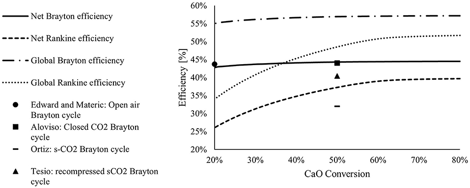
Figure 15. Comparison of the integrated solar CaL system at different material performances.
A novel solution for the storage of excess solar energy harvested into a particle solar calciner for the trigeneration power production is presented in this work. The Brayton cycle (power island) is sized to produce 320 MW and integrated with the solar CaL. The TC/CG-ES uses solar energy to regenerate the calcium carbonate into calcium oxide and carbon dioxide at 950°C. The carbon dioxide produced is compressed at 75 bars, producing heat at low temperature, and expanded when energy is required, producing cold and providing a district cooling network. The three storage tanks for CaO, CaCO3, and CO2 are at ambient temperature, avoiding energy loss for efficient seasonal storage.
The energy release process occurs in the carbonator reactor, taking advantage of the high temperature of the reaction, providing heat to the power block. Several s-CO2 configuration cycles are analyzed, changing several main parameters such as the TIT, RPR, CIT, and split ratio. The best cycle configuration is the intercooling cycle, reaching the maximum solar-to-electrical efficiency of 49.4%.
We perform the pinch analysis to reduce the external heat sources and sinks, optimizing the internal heat recovery. Successively, a parametric analysis is carried out considering three KPIs (i.e., CaO conversion, temperature, and pressure of the carbonator). As a result, we have obtained the optimal operation condition of the carbonator reactor and evaluated how the efficiencies of the system change with the CaO conversion.
CaL storage presents several advantages comparing this storage system with state of the art (i.e., molten salt options): (i) there is no issue of solidification: the compounds can be stored at environmental temperature; (ii) storage at ambient temperature avoids heat loss, therefore can be used as seasonal storage; (iii) the energy density of the analyzed system (2 GJ/m3) is more than two times higher than molten salts (0.9 GJ/m3); and (iv) the maximum temperature achievable with CaL to power the s-CO2 cycle is between 600 and 850°C.
The spent sorbent is a potential material to be fed to the cement plant and other industrial processes (e.g., iron and steel, glass, and pulp), meeting the requirements of the circular economy and reducing landfill material.
The capability of calcium looping to efficiently store solar energy fluctuation and feed a power unit with higher energy density makes this option an optimal candidate for the decarbonization of power production.
The original contributions presented in the study are included in the article/Supplementary Material, further inquiries can be directed to the corresponding author.
SC conducted the analysis and contributed the bulk of the text for this manuscript. AL and SS contributed text and strategic direction. All authors contributed to the conceptual model design. All authors contributed to the article and approved the submitted version.
The authors declare that the research was conducted in the absence of any commercial or financial relationships that could be construed as a potential conflict of interest.
All claims expressed in this article are solely those of the authors and do not necessarily represent those of their affiliated organizations, or those of the publisher, the editors and the reviewers. Any product that may be evaluated in this article, or claim that may be made by its manufacturer, is not guaranteed or endorsed by the publisher.
The Supplementary Material for this article can be found online at: https://www.frontiersin.org/articles/10.3389/frsus.2021.740105/full#supplementary-material
Aggarwal, A., Goyal, N., and Kumar, A. (2021). Thermal characteristics of sensible heat storage materials applicable for concentrated solar power systems. Mater. Today Proc. doi: 10.1016/j.matpr.2021.04.174
Ahn, Y., Bae, S. J., Kim, M., Cho, S. K., Baik, S., Lee, J. I., et al. (2015). Review of supercritical CO2 power cycle technology and current status of research and development. Nucl. Eng. Technol. 47, 647–661. doi: 10.1016/J.NET.2015.06.009
Alovisio, A., Chacartegui, R., Ortiz, C., Valverde, J. M., and Verda, V. (2017). Optimizing the CSP-calcium looping integration for thermochemical energy storage. Energy Convers. Manag. 136, 85–98. doi: 10.1016/J.ENCONMAN.2016.12.093
Anthony, E. (2011). Ca looping technology: current status, developments and future directions. Greenh. Gases Sci. Technol. 1, 36–47. doi: 10.1002/ghg3.2
Bailera, M., Lisbona, P., Romeo, L. M., and Díez, L. I. (2020). Calcium looping as chemical energy storage in concentrated solar power plants: carbonator modelling and configuration assessment. Appl. Therm. Eng. 172:115186. doi: 10.1016/j.applthermaleng.2020.115186
Binotti, M., Astolfi, M., Campanari, S., Manzolini, G., and Silva, P. (2017). Preliminary assessment of sCO2 power cycles for application to CSP solar tower plants. Energy Proc. 105, 1116–1122. doi: 10.1016/J.EGYPRO.2017.03.475
Broda, M., and Müller, C. R. (2014). Sol–gel-derived, CaO-based, ZrO2-stabilized CO2 sorbents. Fuel 127, 94–100. doi: 10.1016/J.FUEL.2013.08.004
Bryner, E., Brun, K., Coogan, S., Cunningham, C. S., and Poerner, N. (2016). Optimizing the CSP Tower Air Brayton Cycle System to Meet the Sunshot Objectives. San Antonio, TX: Soutwest Research Institute.
Cannone, S. F., Stendardo, S., and Lanzini, A. (2020). Solar-powered Rankine cycle assisted by an innovative calcium looping process as energy storage system. Ind. Eng. Chem. Res. 59, 6977–6993. doi: 10.1021/acs.iecr.9b05605
Chen, H., Zhao, C., Yang, Y., and Zhang, P. (2012). CO2 capture and attrition performance of CaO pellets with aluminate cement under pressurized carbonation. Appl. Energy 91, 334–340. doi: 10.1016/J.APENERGY.2011.09.032
Chirone, R., Salatino, P., Ammendola, P., Solimene, R., Magaldi, M., Sorrenti, R., et al. (2013). “Development of a novel concept of solar receiver/thermal energy storage system based on compartmented dense gas fluidized beds,” in Proc. 14th Int. Conf. Fluid.—From Fundam. To Prod. Noordwijkerhout, Netherlands, 95–102.
Denholm, P., Ela, E., Kirby, B., and Milligan, M. (2010). The Role of Energy Storage with Renewable Electricity Generation, Colorado. Available online at: https://www.nrel.gov/docs/fy10osti/47187.pdf (accessed September 30, 2021).
Edwards, S. E. B., and Materić, V. (2012). Calcium looping in solar power generation plants. Sol. Energy 86, 2494–2503. doi: 10.1016/j.solener.2012.05.019
Giovannelli, A., Tamasi, L., and Salvini, C. (2020). Performance analysis of industrial steam turbines used as air expander in Compressed Air Energy Storage (CAES) systems. Energy Rep. 6, 341–346. doi: 10.1016/j.egyr.2019.08.066
Hanak, D. P., and Manovic, V. (2016). Calcium looping with supercritical CO2 cycle for decarbonisation of coal-fired power plant. Energy 102, 343–353. doi: 10.1016/J.ENERGY.2016.02.079
Ho, C. K., and Iverson, B. D. (2014). Review of high-temperature central receiver designs for concentrating solar power. Renew. Sustain. Energy Rev. 29, 835–846. doi: 10.1016/J.RSER.2013.08.099
IEA and Woodhill (2002). Pipeline Transmission of CO2 and Energy Transmission Study. Woking: Woodhill Engineering Consultants.
Islam, M. T., Huda, N., Abdullah, A. B., and Saidur, R. (2018). A comprehensive review of state-of-the-art concentrating solar power (CSP) technologies: current status and research trends. Renew. Sustain. Energy Rev. 91, 987–1018. doi: 10.1016/J.RSER.2018.04.097
Karasavvas, E., Panopoulos, K. D., Papadopoulou, S., and Voutetakis, S. (2020). Energy and exergy analysis of the integration of concentrated solar power with calcium looping for power production and thermochemical energy storage. Renew. Energy 154, 743–753. doi: 10.1016/j.renene.2020.03.018
Kyaw, K., Matsuda, H., and Hasatani, M. (1996). Applicability of carbonation/decarbonation reactions to high-temperature thermal energy storage and temperature upgrading. J. Chem. Eng. JAPAN 29, 119–125. doi: 10.1252/jcej.29.119
Lindfield, G. R., Penny, J. E. T., Lindfield, G. R., and Penny, J. E. T. (2012). Optimization methods. Numer. Methods 2012, 371–432. doi: 10.1016/B978-0-12-386942-5.00008-4
Matsubara, K., Kazuma, Y., Sakurai, A., Suzuki, S., Soon-Jae, L., Kodama, T., et al. (2014). High-temperature fluidized receiver for concentrated solar radiation by a beam-down reflector system. Energy Proc. 49, 447–456. doi: 10.1016/J.EGYPRO.2014.03.048
McPherson, M., Mehos, M., and Denholm, P. (2020). Leveraging concentrating solar power plant dispatchability: A review of the impacts of global market structures and policy. Energy Policy 139:111335. doi: 10.1016/j.enpol.2020.111335
Ortiz, C., Chacartegui, R., Valverde, J. M., Alovisio, A., and Becerra, J. A. (2017). Power cycles integration in concentrated solar power plants with energy storage based on calcium looping. Energy Convers. Manag. 149, 815–829. doi: 10.1016/J.ENCONMAN.2017.03.029
Ortiz, C., Valverde, J. M., Chacartegui, R., Perez-Maqueda, L. A., and Giménez, P. (2019). The Calcium-looping (CaCO3/CaO) process for thermochemical energy storage in concentrating solar power plants. Renew. Sustain. Energy Rev. 113:109252. doi: 10.1016/j.rser.2019.109252
Pardo, P., Deydier, A., Anxionnaz-Minvielle, Z., Rougé, S., Cabassud, M., and Cognet, P. (2014). A review on high temperature thermochemical heat energy storage. Renew. Sustain. Energy Rev. 32, 591–610. doi: 10.1016/J.RSER.2013.12.014
Prieto, C., and Cabeza, L. F. (2019). Thermal energy storage (TES) with phase change materials (PCM) in solar power plants (CSP). Concept and plant performance. Appl. Energy 254:113646. doi: 10.1016/j.apenergy.2019.113646
Segal, A., and Epstein, M. (1999). Comparative performances of ‘tower-top’ and ‘tower-reflector’ central solar receivers. Sol. Energy 65, 207–226. doi: 10.1016/S0038-092X(98)00138-8
Shimizu, T., Hirama, T., Hosoda, H., Kitano, K., Inagaki, M., and Tejima, K. (1999). A twin fluid-bed reactor for removal of CO2 from combustion processes. Chem. Eng. Res. Des. 77, 62–68. doi: 10.1205/026387699525882
Siegel, N. P. (2012). Thermal energy storage for solar power production. WIREs Energy Environ. 1, 119–131. doi: 10.1002/wene.10
Siegel, N. P., and Ermanoski, I. (2013). “A beam-down central receiver for solar thermochemical hydrogen production,” in 42nd ASES National Solar Conference 2013, SOLAR 2013, Including 42nd ASES Annual Conference and 38th National Passive Solar Conference (Baltimore: American Solar Energy Society), 349–355.
Stanmore, B. R., and Gilot, P. (2005). Review—calcination and carbonation of limestone during thermal cycling for CO2 sequestration. Fuel Process. Technol. 86, 1707–1743. doi: 10.1016/J.FUPROC.2005.01.023
Stendardo, S., and Foscolo, P. U. (2009). Carbon dioxide capture with dolomite: a model for gas–solid reaction within the grains of a particulate sorbent. Chem. Eng. Sci. 64, 2343–2352. doi: 10.1016/J.CES.2009.02.009
Tesio, U., Guelpa, E., and Verda, V. (2020). Integration of thermochemical energy storage in concentrated solar power. Part 2: Comprehensive optimization of supercritical CO2 power block. Energy Convers. Manag. X6:100038. doi: 10.1016/j.ecmx.2020.100038
Teske, S., Leung, J., Crespo, L., Bial, M., Dufour, E., and Richter, C. (2016). Solar thermal electricity: global outlook 2016. Available online at: https://www.estelasolar.org/wp-content/uploads/2016/02/GP-ESTELA-SolarPACES_Solar-Thermal-Electricity-Global-Outlook-2016_Full-report.pdf.
Verda, V., and Guelpa, E. (2015). Thermodynamic Methods for the Efficient Use of the Energy Resources (in italian). Esculapio.
Wang, Z. (2019). “Chapter 2—The solar resource and meteorological parameters,” in Design of Solar Thermal Power Plants, ed. Z. Wang (New York, NY: Academic Press), 47–115. doi: 10.1016/B978-0-12-815613-1.00002-X

Keywords: energy storage, calcium looping, thermochemical/compressed gas energy storage, CCU, concentrated solar power (CSP), solar thermal energy, supercritical CO2 Brayton cycle
Citation: Cannone SF, Lanzini A and Stendardo S (2021) An Innovative Calcium Looping Process as Energy Storage System Integrated With a Solar-Powered Supercritical CO2 Brayton Cycle. Front. Sustain. 2:740105. doi: 10.3389/frsus.2021.740105
Received: 12 July 2021; Accepted: 13 September 2021;
Published: 21 October 2021.
Edited by:
Idiano D'Adamo, Sapienza University of Rome, ItalyReviewed by:
Carlos Ortiz, Loyola Andalusia University, SpainCopyright © 2021 Cannone, Lanzini and Stendardo. This is an open-access article distributed under the terms of the Creative Commons Attribution License (CC BY). The use, distribution or reproduction in other forums is permitted, provided the original author(s) and the copyright owner(s) are credited and that the original publication in this journal is cited, in accordance with accepted academic practice. No use, distribution or reproduction is permitted which does not comply with these terms.
*Correspondence: Salvatore F. Cannone, c2FsdmF0b3JlLmNhbm5vbmVAcG9saXRvLml0
Disclaimer: All claims expressed in this article are solely those of the authors and do not necessarily represent those of their affiliated organizations, or those of the publisher, the editors and the reviewers. Any product that may be evaluated in this article or claim that may be made by its manufacturer is not guaranteed or endorsed by the publisher.
Research integrity at Frontiers
Learn more about the work of our research integrity team to safeguard the quality of each article we publish.