- Institut für Raumfahrtsysteme, Technische Universität Braunschweig, Braunschweig, Germany
Large scale additive manufacturing (LSAM) refers to the fabrication of structures that exceed the build volume of conventional additive manufacturing setups. This can be used for in-space manufacturing (ISM), facilitating the production of large functional structures in space which cannot fit within the payload fairing of a launcher system. In this paper, a new approach for a continuous fabrication process of structural elements is presented, combining the reach of a free-flying satellite and a robotic arm, utilizing a fused filament fabrication (FFF) 3D-printing setup. A motion planning algorithm was developed which calculates energy-efficient movement trajectories based on a truss design input combined with the movement constraints of the satellite and robotic arm. Using this printing paradigm, a long support-free truss was manufactured. This approach was further elevated by extending the truss structure along the second planar axis, thus facilitating the manufacture of structures larger than generally possible through a layer-by-layer approach. Subsequently, combining the segmented and continuous printing approach, a planar truss structure was produced.
1 Introduction
In-space manufacturing (ISM) refers to the fabrication of structural parts on orbit. Alongside with on-orbit assembly (OOA) and on-orbit servicing (OOS) it is a key enabler for the cost and resource-efficient manufacture of large functional structures in space in the future (Xue et al., 2020). ISM allows the deployment of structures that exceed rocket payload size limitations by several magnitudes such as solar sails, Sun shields, or star shades. This circumvents complex deployment mechanisms and allows the structures to be optimized for their in-space application, rather than the loads expected during their launch (Tafazoli, 2009; Belvin et al., 2016; Sacco and Moon, 2019; Moraguez and de Weck, 2020). Additive manufacturing (AM) is of specific interest for ISM as it allows the modular and flexible manufacture of large structures and has already been explored by NASA as early as of 1979 with a prototype Beam Builder which was capable of producing truss elements by ultrasonic welding of composite materials (Bodle, 1979; Dunn et al., 2010). More recent examples include the SpiderFab™ project by Tethers Unlimited Inc. and Archinaut developed by Made in Space Inc. Both approaches feature a comprehensive manufacturing system through which individual truss elements are manufactured and assembled by robotic systems (Hoyt et al., 2014; Kugler et al., 2017; Patané et al., 2017; Levedahl et al., 2018). The feasibility of AM under the various space environment conditions (i.e. microgravity, vacuum, temperature gradients) has been demonstrated by several researchers showing no significant disadvantages to their respective counterparts manufactured under terrestrial conditions (O’Connor and Dowling, 2018; O’Connor and Dowling, 2019; Sacco and Moon, 2019; Quinn et al., 2021). However, the impact of the frictionless free-flying environment has only recently been investigated for a segmented AM approach of truss elements (Jonckers et al., 2021; Jonckers et al., 2022).
Large scale additive manufacturing (LSAM) is currently also an active area of interest for the manufacture of large structures for terrestrial applications, offering flexible, tool-less, and mold-less fabrication (Zhai et al., 2014; Thakur et al., 2020). Specifically, the construction industry could use AM to enable automated, cost-effective construction. Three main methods have been researched to facilitate the manufacture of large structures: Large robotic arms, gantry-based systems and mobile robotic platforms (Paolini et al., 2019). Large robotic arms can feature reaches of up to several meters and thus enable the manufacture of structures at meter-scale. For example, the Digital Construction Platform developed by the Massachusetts Institute of Technology is able to print a 3.6 m (12 ft) long polyurethane wall (Keating et al., 2014). Robotic arms have also been used to print support-free structures, where material is extruded and cured in 3D space (Mostafavi and Bier, 2016). This can be more resource efficient when compared to a traditional layer-by-layer approach, as material can be extruded directly along load paths (Liu et al., 2018). This aspect makes it particularly attractive for ISM as raw material would need to be launched from Earth. Another class of LSAM systems are gantry systems which, depending on their setup, are similar to common Cartesian or Delta 3D printers. The manufacture of large structures is enabled by increasing at least one of the axes (Paolini et al., 2019). These systems may also be coupled with robotic arms at the system end effector to add more degrees of freedom (Jiang et al., 2021). Both large robotic arms and gantry systems have in common that—whilst they allow the manufacture of large structures compared to conventional AM methods—the size of the manufactured parts is still limited by the workspace of the system. Mobile base robotic systems coupled with robotic manipulators can increase the workspace virtually infinitely in the 2D plane while being compact systems by nature (Xu et al., 2021). The approach of printing-while-moving has been illustrated by Tiryaki et al. who established a robotic system capable of manufacturing concrete elements exceeding the reach of the robotic arm. The system setup includes marker-based position determination of the mobile base tracking a manually generated trajectory (Tiryaki et al., 2019). The group has also demonstrated collaborative AM simultaneously using two robots, with the research focusing on collision avoidance (Zhang et al., 2018). A mobile base AM system has likewise been proposed by Sustarevas et al. which is capable of simultaneous movement and extrusion using an Optitrack tracking system for position determination (Sustarevas et al., 2018). More recently, trajectory generation using the rapidly-exploring random tree algorithm (RRT*) has been demonstrated respecting the manipulator reachability map and allowing obstacle avoidance (Sustarevas et al., 2021). Both approaches for trajectory generation by Tiryaki et al. and Sustarevas et al. focus on collision avoidance of wheeled robotic platforms, and do not take energy consumption into consideration. For in-space applications, fuel consumption would be a major aspect for the assessment of efficient manufacturing methods. Furthermore, research on LSAM has only focused on layer-by-layer 3D-printing for terrestrial applications. To the authors’ knowledge, no research has been conducted into support-free fabrication using mobile robotic platforms.
A challenging aspect of large-scale robotic systems is the end effector position determination and control within the global reference frame. Tiryaki et al. used marker-based position tracking of the mobile base, achieving an accuracy of 2.2 mm. Through position feedback control, Sustarevas et al. were able to achieve average trajectory tracking errors of 6 mm. For a large-scale cable-driven AM setup, Chesser et al. also used optical position tracking and reduced the end effector position error to 0.9 mm compared to 16 mm for an open loop system (Chesser et al., 2022). All presented systems have in common that they intend to deposit materials such as foam or concrete through a nozzle with a diameter of several centimetres. Thus, minimization of end effector errors were not as crucial for successful printing demonstrations. In comparison, we presented a closed-loop printing approach using a mobile base, achieving a printing accuracy of less than 0.3 mm, allowing the successful deposition of thermoplastic materials through a 1.2 mm diameter nozzle (Jonckers et al., 2022).
To prevent the base of the robot from recontacting already printed material, structures which are large in 2 dimensions are typically split into non-continuous elements or segments, the practicalities of which were investigated by Li et al. This approach has also been investigated for the printing of large structures by several stationary robotic arms (Shen et al., 2019; Li et al., 2021).
In our previous work, we introduced a novel approach to additively manufacture functional structural elements through free-form fabrication directly in a free-flying environment (Jonckers et al., 2021). There, we showed the possibility to fabricate large support-free structures through fused filament fabrication (FFF) using a robotic arm mounted to a free-flying satellite. The free-flyer would aim to maintain a fixed position during the printing process, using a PID controller to counteract disturbances such as the material deposition forces or residual accelerations. However, any position error of the free-flyer was translated directly to the end effector and therefore negatively impacted the print accuracy. To improve print accuracy, we then developed a control approach to compensate for any remaining position error using the robotic manipulator. This enabled parts to be printed with a mean printing error of 0.27 mm (Jonckers et al., 2022). As the Free-flyer attempted to maintain a fixed position during the printing process, the size of components printed was limited by the robotic arm’s workspace. To print long structures, it was therefore necessary to split them into smaller overlapping segments—each of which would be printed in turn. The introduction of joints between segments was posited to reduce the strength of the manufactured parts. In this paper we demonstrate a continuous printing method that eliminates these joints by, for the first time, combining the movement of the robotic arm and the satellite simulator (free-flyer), thereby allowing the manufacture of arbitrarily long structures, without requiring any joints. A motion planning algorithm is presented that computes independent trajectories for the robotic arm and the free-flyer, which minimizes energy expenditure while satisfying the work-space constraints of the robotic arm. To the authors’ knowledge, no research has been conducted regarding energy-efficient LSAM trajectory planning in a free-flying environment. We then present an approach to extend this capability to the printing of structures with arbitrary size in two dimensions. An algorithm is used to split structures into strips with unlimited length, and a width and height which fit into the robotic arm’s workspace. These are printed in turn to prevent any clashes. A joining method is used to enable bonding over multiple layers.
2 Experimental Setup
2.1 Satellite Simulation Test Bed
The Experimental Lab for Proximity Operations and Space Situational Awareness (ELISSA), an active 4 × 7 m air bearing table, is used to emulate the micro gravity space environment (Ben-Larbi et al., 2016; Trentlage et al., 2018; Yang et al., 2021). A blower system generates an air cushion on the table surface on which free-flyers (FF) can float frictionless with 3 degrees of freedom (DOF), translationally in x- and y-direction and rotationally around the z-axis (θ). The free-flyers are propelled by an 8-propeller thruster setup. Each thruster uses a 30 W brushless DC motor with a 3-blade propeller, which supplies a maximum force of 2 N. An on-board computer allows two-way wireless communication. Robot Operating System (ROS) is used for communication and control between subsystems and an Optitrack optical tracking system with six Primex 17 W cameras provides position determination with sub-millimeter accuracy. Figure 1 shows the free-flyer on the air-bearing table along with three of the six tracking cameras.
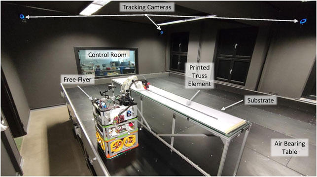
FIGURE 1. Experimental setup showing the air bearing table and optical tracking system as well as the free-flyer along with the stationary substrate.
The modular free-flyer is equipped with a payload module containing a MECA5001 robotic arm along with a direct-drive fused filament fabrication (FFF) print setup mounted to it (see Figure 2A and Section 2.2). The robotic arm has a total mass of 4.5 kg, whilst the extruder end effector has a mass of 0.26 kg. When fully extended, the end effector is located 370 mm from the base link of the arm (see rmax in Figure 2B), and it can be positioned with a repeatability of 0.005 mm The tool center point (TCP) of the robotic arm is set to the tip of the printer nozzle (see Figure 2B). The robotic arm uses an internal controller allowing position and velocity control. The free-flyer pose is controlled through three separate proportional integral derivative (PID) controllers for x, y and θ.2 Simultaneous position and velocity control can be achieved in the trajectory generation process. The controller gains are tuned for trajectory tracking to minimize steady state error and avoiding oscillations. The coordinated movement of robot and free-flyer is harmonized through a common trajectory that contains target positions for both systems; the time step for position updates is dt = 60 ms. The robotic arm is able to adjust for position and orientation errors of the free-flyer through a previously developed control system (Jonckers et al., 2022). The TCP pose of the robotic arm within the global frame is calculated by combining the tracking information of the free-flyer from the optical tracking system and the position feedback of the robotic arm.
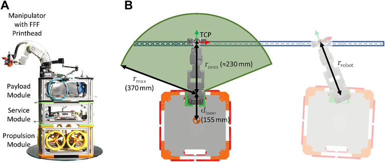
FIGURE 2. The free-flyer is a modular structure with separate propulsion, service and payload module (A). The latter is equipped with a manipulator and FFF printer setup. The schematic top view shows a 100 cm long truss to be printed (B). The workspace of the manipulator is highlighted in green and a free-flyer position counteracting a pose deviation in translucent. The relevant coordinate frames are indicated by the red and green arrows.
2.2 Printing Method
The aforementioned setup is capable of 3D printing onto a stationary platform. The printing of truss structures with an unlimited length by splitting the structure into segments which fit into the robotic manipulator’s workspace has already been established (Jonckers et al., 2022). However, the joints between segments constitute weak spots in the overall structure. It is therefore preferable to manufacture the structure as a single continuous print without joints. Such an approach would enable the manufacture of long support structures, for example for solar arrays, radiators, or similar.
To demonstrate the capability to print long, continuous structures exceeding the workspace of the robotic arm, a free-form 1D-truss3 structure with a length of 100 cm is printed. Free-form or support-free additive manufacturing describes the extrusion of material into 3D space to produce the desired form. It is advantageous as it allows the manufacture of sparse structures, such as truss elements, whilst keeping mass and material use low (Liu et al., 2018). The structure can be extended to any length. For the simulation on ELISSA, this means the length is only limited by the size of the experimental setup, whilst a spacecraft would be limited by its fuel and material stocks.
For more complex large structures required in space, such as antenna reflectors, starshades, or optical telescopes, it is necessary to print structures with large dimensions in multiple Cartesian directions (i.e. not just long and thin structures). Due to the potential issue of the spacecraft re-contacting material which has already been printed, it is desirable to split the structure into segments—despite the acknowledged impact to strength. To demonstrate the capability to print objects with large dimensions in two Cartesian directions, a planar truss structure was printed. As the air bearing table only allows movement in 3 DOF, it is not possible to demonstrate the printing of objects with large dimensions in more Cartesian directions.
The schematic shown in Figure 2B illustrates a 1D-structure to be printed along with the free-flyer and manipulator during printing. The printing process starts with the base layer, followed by the vertical cross beams and then the top layer. The print order is structured in a way to allow continuous extrusion throughout the whole print. This process is illustrated by a video given in the Supplementary Material which shows the print of a 20 cm long truss at 4x speed. The printing setup consisting of the manipulator and FFF hot end and extruder is controlled through G-code commands similar to a conventional 3D-printer. Prior to the printing process, commands are parsed to a time-variant trajectory in Cartesian coordinates (see Section 3.1) with the free-flyer on-board computer interpreting the trajectory information during the printing process and passing it to the manipulator, extruder and hot end.
For the printing process, a Volcano hot end4, with a Titan direct drive extruder, and a 1.2 mm diameter nozzle4 were used with 2.85 mm PLA5 filament. PLA was chosen as the printing material due to its low printing temperature, as well as ease of printibility (Alsoufi et al., 2019). However, PLA does not feature the temperature resistance nor the mechanical strength that would be desirable for structural elements in space. Future experiments will explore the use of engineering thermoplastics such as PEEK and ULTEM, which are compatible with the FFF process, and have been investigated for space use (Dmitry G. Luchinsky et al., 2018; Rinaldi et al., 2020). The direct drive setup was chosen to ensure consistent low extrusion rates and to mitigate filament oozing between discontinuous segments compared to a bowden system. The 1.2 mm nozzle allows the manufacture of stiff support-free structures while being less susceptible to TCP position deviations. The print temperature is set to 180°C to reduce the time required for the molten filament to solidify (Alsoufi et al., 2019). An extrusion rate of 3.33 mm/s (3.77 mm3/s) was chosen as it provides a good compromise of print time, control system accuracy and print quality (Jonckers et al., 2022).
3 Algorithms
3.1 Trajectory Planning
The G-code generated in Section 2.2 represents the coordinates of the to-be-printed structure within a local coordinate frame. In order to print structures of a size larger than the reach of the robotic arm in a continuous manner, the simultaneous movement of the robotic arm and the free-flying satellite simulator is required. The free-flyer is moved along the length of the truss element (x-direction), moving the workspace of the robotic arm while printing. Within this section, an algorithm for the automatic generation of free-flyer and manipulator trajectories is presented.
The terms path and trajectory are used to describe the planned movement of a robotic system. A path describes the coordinates that the robot TCP shall reach during movement. A trajectory is the time-variant movement along a path, thus incorporating a velocity and acceleration profile. The trajectory generated by the algorithm has to fulfill a list of requirements explained hereafter. Firstly, the algorithm has to ensure that the distance between the base of the robotic arm mounted onto the free-flyer and the target TCP position at no point exceeds the physically possible reach of the robotic arm, the so-called workspace (see Figure 2B). Furthermore, the accelerations of the free-flyer should be minimized, not only to stay within the physically possible thrust limit Fmax of the free-flyer’s motors (equivalent to amax = 30 mm/s2). High accelerations may also overstrain the free-flyer’s control system introducing deviations from the target state that the robotic arm cannot adequately compensate due to the internal time lag of system. A maximum acceleration of 0.5 mm/s2 is chosen. Lastly, the trajectory shall also be defined in a way to reduce the free-flyer’s energy expenditure.
G-code itself is a programming language defining a tool path but cannot directly be read as a time-variant tool path trajectory. The G-code instructions generated in Section 2.2 are therefore translated to a time-variant trajectory. Both trajectories, the one of the robotic arm and the free-flyer will be synchronized at a period of T ≥ 60 ms which is the maximum update rate of the robotic arm. A parser reads the G-code instructions and transforms them to a continuous time series of Cartesian coordinates (Jonckers et al., 2022).
Based on the TCP trajectory, a free-flyer trajectory has to be generated. Manual path planning is trivial for simple print geometries but increasingly difficult for complex geometries (Zhang et al., 2018; Tiryaki et al., 2019). Satisfying the trajectory requirements—robotic arm reach, low accelerations and low fuel consumption—make an efficient manual trajectory generation nearly impossible. In a free-flying environment, the low energy expenditure and acceleration requirements complement each other. Eq. 1 gives the work WFF required by the free-flyer to move along a trajectory. It is proportional to the theoretical fuel consumption of the free-flyer propulsion system and can thus be used as an indicator for the trajectory efficiency.
It is dependent on the free-flyer mass m, the acceleration given as the second derivative of the position
In signal processing, a low-pass filter modifies a signal so that only components with a frequency fc lower than a threshold value are passed, while components with a higher frequency are attenuated. The idea is to generate the free-flyer trajectory by applying a filter to the TCP trajectory which will then be shifted to a local free-flyer reference frame. Treating the TCP path in the horizontal plane y(x) as two time series x(t) and y(t), a low-pass filter will attenuate the rate of change of these signals. The z-component of the TCP trajectory is disregarded as all printed structures created within the scope of this paper have a height of less than 10 mm. The change of the robotic arm’s reach due to the z-component is negligible. As the first-order derivatives
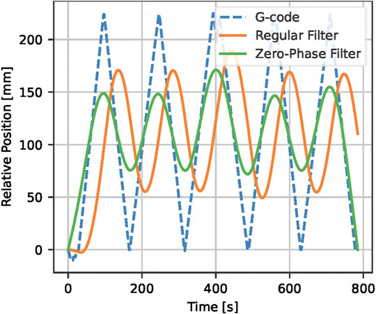
FIGURE 3. Comparison of regular and zero-phase low-pass filtering for a coordinate time series x(t) with a cut-off frequency fc = 5 mHz shows a time delay of 40 s for a regular filter compared to zero time delay using zero-phase filtering.
The relationship of cutoff frequency and the estimated robotic arm reach is non-trivial and an analytical solution satisfying the defined requirements cannot be determined. Therefore, the cutoff frequency is iteratively lowered until the reach of the robotic arm exceeds the specified threshold value. This approach is shown in Algorithm 1. Once the threshold value is exceeded, the previous cutoff frequency is used to generate the filtered free-flyer position data.
An in-depth analysis of maximum reach and acceleration as well as total required work in dependence of the cutoff frequency is performed for a 100 cm long 1D-truss element (see Section 2.2). Figure 4A shows the free-flyer’s maximum acceleration amax in dependence of the cutoff-frequency. The maximum acceleration changes nearly linearly with increasing fc as the attenuation is lowered. In any case, amax is significantly smaller than the desired limit. The mean acceleration
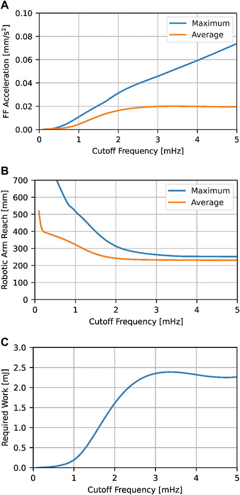
FIGURE 4. Influence of the cutoff frequency fc on the average and maximum free-flyer acceleration (A) and robotic arm reach (B) as well as the theoretical work required by the propulsion system (C) for a 100 cm long 1D-truss.

FIGURE 5. Comparison of two filtered signals at different cutoff frequencies to the G-code of a 100 cm 1D-truss element. The free-flyer and nozzle trajectories are overlayed for better visual comparison while they are offset in the experiment by the nominal reach (rnom = 230 mm).
3.2 2D-Structures
The algorithm described in the previous section coupled with the free-form printing technique described in Section 2.2 is sufficient for the printing of structures with an unlimited size in a single Cartesian direction (1D-printing) by a mobile robot with an accompanying robotic arm. For in-space applications, this could be used to manufacture truss structures to support solar arrays, or similar. More complex large structures would, however, have large dimensions in multiple Cartesian directions. In 3D space, it would be possible to print a 3D structure with arbitrary size, by using a traditional layer-by-layer approach, where the spacecraft flies above the printed structure. However, this is not possible to simulate on an air bearing table. Furthermore, for structures with a large height, this quickly becomes inefficient, as the spacecraft must fly over the whole structure for each layer printed. Therefore, an algorithm has been formulated which enables the printing of a structure with unlimited size in two Cartesian directions, by splitting it into segments. This also ensures that there is no conflict between the robot trajectory and already printed material, and could therefore be used for terrestrial applications. Furthermore, this approach could enable multiple systems to work together to produce the final structure, as investigated by Shen et al. (2019). It could be extended to structures with unlimited sizes in all three Cartesian directions by repeating the algorithm every number of layers, determined by the workspace of the robotic manipulator. This work seeks only to examine whether such an approach is feasible, future work will investigate optimisation of the splitting algorithm, and will compare the energy efficiency when compared to a layer-by-layer approach.
In general, the algorithm splits each layer of the structure to be printed into a series of strips with a width smaller than the reach of the robotic arm but an unrestricted length. Each strip is then printed using the above-mentioned algorithm for 1D-structures. To ensure that the trajectory of the mobile robot does not intersect with already printed material, all layers in a given strip are printed before beginning the subsequent strip. The strips are joined together by overlapping them. As seen in Figure 6, the first layer of the second strip overlaps the first layer of the first strip. This is continued until the final layer, where no overlapping takes place, to ensure a constant height. This overlapping method was chosen as it creates a joint from the first layer, preventing it from moving in relation to the already printed segment.

FIGURE 6. Illustration of the method used to overlap and join strips together. The strip printed first is shown in blue, the strip printed second is shown in green. L is the overlap length. This method ensures that the strips are joined together from the first layer.
The algorithm functions in the following manner: first, the G-code of the large structure is reduced to the lines which are to be extruded; these lines are then sorted into categories based on which strip they belong to. Lines which cross the boundaries between strips are split into multiple segments, such that each segment fits in a strip. Lines which would exactly coincide with a boundary are assigned to the strip which is to be printed first. To produce the staggered overlap, the boundaries are moved by the desired overlap length for each layer. Figure 7 illustrates an example, where a planar truss structure has been split into three segments with width W. This should be set such that
where R is the manipulators’s reach in the widthwise direction. This is required, as when an object with the maximum height is printed, the overlap for the top layer will require the printhead to move to the furthest point of the previous strip. The overlapping method also limits the height of the structure, such that the maximum number of layers to be printed Nmax is given by
where L is the overlap length, and
The lines for each layer in each strip are then joined into a series of continuous paths. The first path is initialised by starting with a nominal position, typically the origin of the print reference frame. The line with the closest start or end point to this position is the first line in the first path. The path is continued by searching for another line with a point which matches the opposite point to the current line. This process is continued until no matches are found, then a new path is begun by finding the closest point to the current end point. Figure 8 is a flowchart detailing this process. An example of the process is shown in Figure 9. First the line closest to the origin (marked by a cross) is selected and added to the path (highlighted in blue). The line connected to the previously selected line is then added to the path (highlighted in blue). This process continues until a line which does not have another line connected is selected. At this point, a new path is started and the next nearest line is selected (shown in green). This is repeated until all lines are assigned to a path. The whole process is then repeated for the next layer and once all layers are completed for the next strip. It should be noted that where two lines are connected to a selected line, there is no rule dictating which will be selected next.
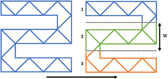
FIGURE 7. Illustration of a planar truss (blue; left side) structure being split into strips (blue, green, orange; right side) with width W. The strips are then printed in the order denoted, removing the possibility of a clash between the robot and printed material.
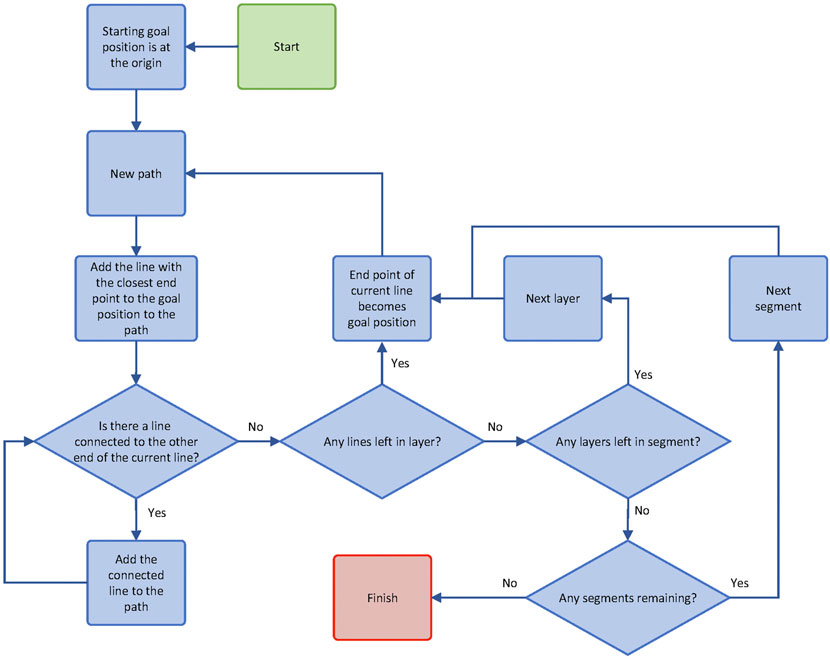
FIGURE 8. A flowchart detailing the process used to produce continuous print paths for each layer of each strip in the splitting algorithm.
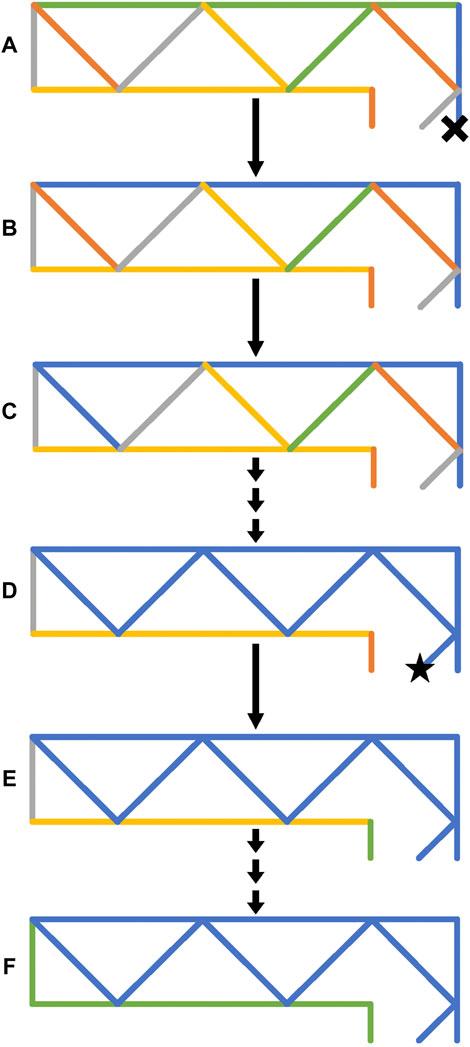
FIGURE 9. A series of lines to be printed for a layer of a segment. In (A), unsorted lines are shown in multiple colours, the origin is shown as a black cross. The line in blue is added to the first path as it is the closest to the origin. In (B), the line which is joined to the previously selected line is added to the path and is therefore coloured blue. This process is repeated in (C,D) until a line is added to the path which is not connected at the opposite end. In (E) a new path is started with the line nearest to the goal position (shown as a black star) is added (shown in green). This is repeated until all lines are assigned to a path (F).
The algorithm could be further extended to all three Cartesian directions by stacking multiple layers of 2D-structures on top of each other. This would require segmenting the object to be printed in two directions. For this approach to be successful, the spacecraft must travel above (or below) the previously printed layer. A new joining method would also need to be devised for joining these layers together.
4 Results and Discussion
4.1 Trajectory Tracking
The performance of the free-flyer trajectory tracking controller with disturbance compensation by the robotic arm is evaluated through a dry run; the free-flyer and robotic arm move along a trajectory while there is no deposition of material. The extrusion of filament is disabled so that disturbances related to the extrusion process such as the deposition forces between nozzle and substrate are excluded and the proficiency of the free-flyer control system and disturbance compensation algorithm can be assessed separately. The control system still has to counteract external disturbances such as residual accelerations of the air bearing table and free-flyer movements due to dynamic coupling of the robotic arm and mobile base (Ivanov et al., 2018; Rybus et al., 2019; Jonckers et al., 2021). The test is performed on a modified truss trajectory featuring a 50 cm long cross-beam section followed by a linear movement with change of direction (see Figure 10A). This way, all relevant aspects of a truss structure can be assessed in a shorter time period.
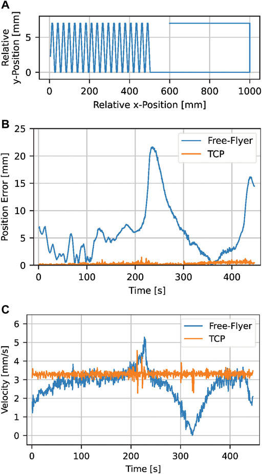
FIGURE 10. Evaluation of the PID controller performance for trajectory tracking with compensation of disturbances through the robotic arm in a dry run. This is done for a cross beam segment and a linear segment in the x-y-plane (A). While the free-flyer experiences position errors up to 22 mm, the compensation algorithm of the robotic arm keeps the average TCP error at ±0.26 mm (B). The TCP target velocity of 3.33 mm/s is tracked well with a standard deviation of 0.14 mm/s (C).
The trajectory tracking quality is shown in Figure 10B by displaying the free-flyer and TCP position errors ɛFF and ɛTCP (Euclidean distance between target and actual trajectory) over time. The free-flyer experiences target position deviations up to 22 mm. The two maxima repeatedly occur at the same location on the air bearing table and can be correlated to a change of residual acceleration in this particular spot. The state deviation is regarded as acceptable because it is well within the reach of the robotic arm. Furthermore, its rate of change is adequately low, allowing the robotic arm to counteract without oscillating behavior. The average position error of the TCP is ±0.26 mm which is significantly smaller than the nozzle diameter. Thus, the position tracking capabilities of the robotic arm are considered satisfactory and suitable for additive manufacturing.
Another important aspect besides position tracking is velocity control. The print head velocity within the global reference frame vTCP has to remain proportional to the extrusion rate of the filament vextr to ensure a consistent print quality. This relationship is defined as the flow rate fr:
Varying flow rates cause irregularities in the extruded material, consequently introducing weaker spots in the deposited structure (Pappas et al., 2021). Control of the flow rate through the extruder motor is difficult as its extrusion rate reacts with a time delay to a change of the extruder motor speed due to the back pressure within the hot end (Choulak et al., 2004). Therefore, accurate velocity control of the print head itself is required. A nominal velocity of 3.33 mm/s was chosen as to be used for the actual manufacturing process (see Section 2.2). Figure 10C shows the TCP velocity vTCP within the global reference frame comparing it to the free-flyer velocity which purposely changes. The free-flyer follows its velocity profile with some deviations due to position errors caused by residuals accelerations (comparing Figures 10B,C) with a standard deviation of 0.46 mm/s. The TCP velocity, however, shows no significant deviations from the TCP target velocity with the standard deviation being 0.14 mm/s (4.2% of vTCP). It can be assumed that this is sufficiently accurate for the actual additive manufacturing process.
4.2 Continuous Printing
The capabilities of the continuous printing algorithm introduced in Section 3.1 are demonstrated by the continuous manufacture of a 100 cm long truss structure on the satellite simulation test bed ELISSA (see Section 2.1). For trajectory generation, the threshold robotic arm reach rlim is set to 270 mm to allow free-flyer trajectory deviations of up to 100 mm as the maximum reach of the robotic arm in the used configuration is 370 mm. As shown in Figures 4A,B, this results in a cut-off frequency fc = 2.5 mHz and a maximum expected acceleration amax = 0.04 mm/s2. The total print duration is 50 min.
An image of the finished printed truss structure is shown in Figure 11A depicting overall good print quality. There are no joining errors of the cross beam elements in the horizontal plane or with the first layer of the truss structure. A few vertical nodes were not joined to the top layer due to material sagging during the cooling phase, an issue not occurring in a full microgravity environment. The diameter of the extruded material varies between 1.02 and 1.2 mm. This is associated to the material being held under tension during the extrusion process as well as velocity deviations of the free-flyer both causing the extruded material to stretch, i.e. reduce its diameter. The closeup images given in Figures 11B,C show a side and top view of the truss, respectively. The back layer of the print is shaded in each of the views for a better visual distinction of the layers. The successful joins of nodes in the horizontal and in the vertical plane are clearly visible.
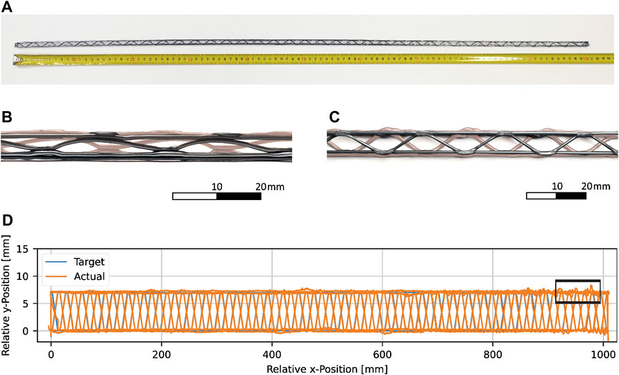
FIGURE 11. Photo of a 100 cm long truss (A) printed using the continuous print algorithm. A side and top view of the truss are shown in (B,C), respectively with the rear layer of the print being shaded. A comparison of the target TCP to the recorded TCP is given in (D) with larger target path deviations highlighted by a box which corresponds to the top view given in (C).
The recorded TCP position is shown in orange in Figure 11D comparing it to the target TCP position (blue). A box highlights a segment of the truss with larger target path deviations than for the rest of the truss. This section corresponds to the top view given in Figure 11C. The increased error in the y-direction matches the offset of the horizontal nodes of the first layer which may have been caused by a reduced distance between substrate nozzle (e.g. warping of the print substrate) and in turn increased deposition forces within the recontacting areas. However, the deviations shown in Figure 11D do not fully match the ones shown in the image given in Figure 11C. This is because the filament does not necessarily stay in the exact position in which it was extruded. During the cooling phase after extrusion, the filament is still pliable and may be moved towards the target path when the robotic arm corrects the position of the TCP. Furthermore, the position data provided by the optical tracking system is subject to error. For some free-flyer positions and orientations as well as robotic arm poses, tracking markers may overlay each other or become blocked from the tracking cameras, reducing the positional accuracy. Especially under fluctuating conditions, this causes noise in the position data which caused repeatable position results in the section shown in Figure 11D. Moreover, it must be noted that the x-y-plot shown in Figure 11D is significantly skewed in the y-direction exaggerating the errors along this axis. This is further intensified by the line width which is thinner in the y-direction than the actual diameter of the nozzle.
The mean TCP error
With changing tension and other forces exerted onto the nozzle, the torque fluctuates and the propulsion system needs to constantly adjust, leading to the aforementioned error in the x-direction. These torques could also be counteracted by reaction wheels in order to reduce the fuel consumption and is subject of future research (Ellery, 2004). Lastly, the TCP position within the robotic base reference frame is calculated at each time step of the trajectory, taking into account the current free-flyer velocity. As the velocity is calculated as the derivative of the free-flyer position, coupled with a moving average filter, it underlies a delay and the noise of the position data.
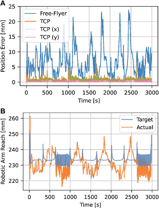
FIGURE 12. Evaluation of the free-flyer and robotic arm position error (A) during the print of a 100 cm long truss structure. The free-flyer position error reaches up to 24 mm; however, the robotic arm can compensate it reaching an average TCP error of 0.75 mm. The robotic arm reach r (B) stays well within the physical limits of rmax = 370 mm.
The average free-flyer position error is 6.80 mm and is evenly distributed on both axes (
The standard deviation of the TCP velocity is 0.38 mm/s. It can be assumed that a TCP velocity higher than the extrusion velocity (i.e. vTCP > 3.33 mm/s and therefore fr < 100%) leads to a proportional straining of the extruded filament (Percoco et al., 2021). This corresponds to the observed diameter reduction of the extruded material to as low as 1.02 mm but does not affect the structural integrity of the manufactured structures.
4.3 2D-Structures
The algorithm described in Section 3.2 was used to print a planar truss structure, with overall dimensions 150 mm × 210 mm. The shape of the structure was chosen to illustrate that the joining method would work for angled as well as horizontal lines. It was split into three strips with nominal widths of 43 mm, 60 and 47 mm. These widths were also chosen to highlight the joining method. The structure consisted of four layers, with a layer height of 1 mm. Figure 13A shows a plot of the nominal G-code, whilst Figure 13B shows the G-code after the splitting algorithm has been applied. The separate paths are illustrated as separate colours.
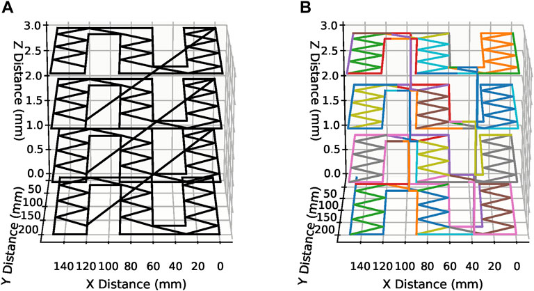
FIGURE 13. Plots of (A) the G-code of the planar truss before the splitting algorithm and (B), the G-code of the planar truss after being split into segments.
The planar truss was successfully printed as shown in Figure 14 where a closeup of the join between two strips is highlighted. It can be seen that the three strips have successfully been joined into one complete structure, though there are some printing errors. In particular, it was found that, despite retracting the filament at the end of each path, the extruded material would be dragged with the nozzle when it moved. This is particularly noticeable around the joints in Figure 14. This results in material at a height above the nominal layer height, and when the subsequent layer is printed, higher friction is experienced, which in turn leads to printing errors. By modifying the behaviour of the printhead, it may be possible to improve this, for example by retracting the filament faster, or further.
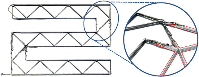
FIGURE 14. An image of the printed planar truss. A closeup of the joint between two strips is shown with the segment printed first being shaded and outlined in red.
Though the use case envisioned in this paper is the manufacture of large structures on-orbit, the algorithm could be used in other scenarios making use of mobile robots equipped with robotic manipulators to produce structures using AM. For example, research has been conducted into the use of wheeled robots with robotic arms for manufacturing concrete structures for the construction industry (Zhang et al., 2018; Tiryaki et al., 2019). Assuming that the joints between strips do not reduce the strength of the structure, it would be possible to print structures larger than otherwise possible.
5 Conclusion and Outlook
A new approach for large-scale additive manufacturing adjusted for the free-flying environment for in-space manufacturing was presented within this paper. An algorithm was developed to allow the continuous manufacture of functional 1D-structures by combining the reach of a free-flying satellite and collaborative manipulator with FFF printing setup with simultaneous extrusion and satellite movement. The algorithm distributes the required motion between the free-flyer and robotic arm by means of low-pass filtering any given printing instruction (G-code). Through an iterative calculation approach, the free-flyer motion is reduced to minimize the work required for the motion of the free-flyer while complying with the workspace constraints of the robotic arm. The approach was tested on an air bearing table using a fan propelled satellite simulator, equipped with a robotic manipulator printing onto a stationary substrate. It was shown that the free-flyer could track the calculated trajectory well due to the low accelerations required. Position deviations were counteracted by the robotic arm resulting in printing errors of less than 0.75 mm during the manufacture of a 100 cm long truss structure. Along with good TCP velocity tracking to ensure a constant extrusion rate, satisfactory printing results were achieved with zero node joining failures due to TCP position errors. A second algorithm was developed that allows the manufacture of 2D elements with the algorithm automatically splitting structures into segments which are within the workspace of the robotic arm. The algorithm is capable of reducing the number of travel moves per segment through G-code analysis and automatically modifies the structure to allow joining between segments. An experiment showed the successful print of a 150 × 210 mm structure consisting of three segments with good joining results between them. The size of the 1D- and 2D-structures can be increased arbitrarily only being limited by the size of the experimental setup. For future works, it is planned to elevate the current approach from a stationary to a moving substrate. A second free-flyer—either cooperative or non-cooperative—will act as a substrate to demonstrate the feasibility of the presented manufacturing algorithm for on-orbit repair. Free-flyer trajectory deviations may be reduced by incorporating a reaction wheel to counteract torques generated by deposition forces which could be sensed by load cells mounted to the print head for feedback control.
Data Availability Statement
The raw data supporting the conclusion of this article will be made available by the authors, without undue reservation.
Author Contributions
OT: Conceptualisation, Methodology, Software, Validation, Formal analysis, Investigation, Writing—Original Draft, Writing—Review and Editing, Visualisation. DJ: Conceptualisation, Methodology, Software, Validation, Formal analysis, Investigation, Writing—Original Draft, Writing—Review and Editing, Visualisation. AT: Conceptualisation, Supervision, Writing—Review and Editing.
Conflict of Interest
The authors declare that the research was conducted in the absence of any commercial or financial relationships that could be construed as a potential conflict of interest.
Publisher’s Note
All claims expressed in this article are solely those of the authors and do not necessarily represent those of their affiliated organizations, or those of the publisher, the editors and the reviewers. Any product that may be evaluated in this article, or claim that may be made by its manufacturer, is not guaranteed or endorsed by the publisher.
Acknowledgments
We acknowledge support by the Open Access Publication Funds of Technische Universität Braunschweig.
Supplementary Material
The Supplementary Material for this article can be found online at: https://www.frontiersin.org/articles/10.3389/frspt.2022.900549/full#supplementary-material
Abbreviations
AM, Additive Manufacturing; CNC, Computer Numerical Control; DOF, Degrees of Freedom; ELISSA, Experimental Lab for Proximity Operations and Space Situational Awareness; FF, Free-Flyer; FFF, Fused Filament Fabrication; GNC, Guidance, Naviation and Control; ISAM, In-Space Additive Manufacturing; ISM, In-Space Manufacturing; JWST, James Webb Space Telescope; OBC, On-Board Computer; OOA, On-Orbit Assembly; OOS, On-Orbit Servicing; PEEK, Polyether Ether Ketone; PID, Proportional-Integral-Derivative (Controller); RRT, Rapidly-Exploring Random Tree; TCP, Tool Center Point.
Footnotes
1Mecademic Robotics, Canada.
2Px = 60, Ix = 1.5, Dx = 150 Px = 60, Ix = 1.5, Dx = 150 Pθ = 2, Iθ = 0.05, Dθ = 6.
31D refers to the structure being significantly larger along one axis compared to the other two axes.
4E3D, United Kingdom.
5Das Filament, Germany.
References
Alsoufi, M., Alhazmi, M., Suker, D., Alghamdi, T., Sabbagh, R., Felemban, M., et al. (2019). Experimental Characterization of the Influence of Nozzle Temperature in Fdm 3d Printed Pure Pla and Advanced Pla+. Ajme 7, 45–60. doi:10.12691/ajme-7-2-1
Belvin, W. K., Doggett, W. R., Watson, J. J., Dorsey, J. T., Warren, J. E., Jones, T. C., et al. (2016). “In-Space Structural Assembly: Applications and Technology,” in 3rd AIAA Spacecraft Structures Conference (Reston, Virginia: American Institute of Aeronautics and Astronautics).
Ben-Larbi, M. K., Grzesik, B., Trentlage, C., Yang, J., Höfner, K., and Stoll, E. (2016). “Algorithm and Technology Development for Active Debris Removal at the Institute of Space Systems,” in Deutscher Luft- und Raumfahrtkongress.
Bodle, J. G. (1979). Development of a Beam Builder for Automatic Fabrication of Large Composite Space Structures. Tech. Rep. Houston, TX: General Dynamics Convair Division.
Chesser, P. C., Wang, P. L., Vaughan, J. E., Lind, R. F., and Post, B. K. (2022). Kinematics of a Cable-Driven Robotic Platform for Large-Scale Additive Manufacturing. J. Mech. Robotics 14, 1. doi:10.1115/1.4052010
Choulak, S., Couenne, F., Le Gorrec, Y., Jallut, C., Cassagnau, P., and Michel, A. (2004). Generic Dynamic Model for Simulation and Control of Reactive Extrusion. Ind. Eng. Chem. Res. 43, 7373–7382. doi:10.1021/ie0342964
Dunn, J. J., Hutchison, D. N., Kemmer, A. M., Ellsworth, A. Z., Snyder, M., White, W. B., et al. (2010). 3D Printing in Space: Enabling New Markets and Accelerating the Growth of Orbital Infrastructure. Mountain View, CA.
Ellery, A. (2004). An Engineering Approach to the Dynamic Control of Space Robotic On-Orbit Servicers. Proc. Institution Mech. Eng. Part G J. Aerosp. Eng. 218, 79–98. doi:10.1243/0954410041321998
Hoyt, R. P., Cushing, J., Slostad, J., and Jimmerson, G. (2014). “Trusselator: On-Orbit Fabrication of High-Performance Composite Truss Structures,” in AIAA SPACE 2014 Conference and Exposition (Reston, Virginia: American Institute of Aeronautics and Astronautics) (AIAA SPACE Forum). doi:10.2514/6.2014-4337
Ivanov, D., Koptev, M., Mashtakov, Y., Ovchinnikov, M., Proshunin, N., Tkachev, S., et al. (2018). Determination of Disturbances Acting on Small Satellite Mock-Up on Air Bearing Table. Acta Astronaut. 142, 265–276. doi:10.1016/j.actaastro.2017.11.010
Jiang, J., Newman, S. T., and Zhong, R. Y. (2021). A Review of Multiple Degrees of Freedom for Additive Manufacturing Machines. Int. J. Comput. Integr. Manuf. 34, 195–211. doi:10.1080/0951192X.2020.1858510
Jonckers, D., Tauscher, O., Stoll, E., and Thakur, A. (2021). “Feasibility Study of Large-Format, Freeform 3d Printing for On-Orbit Additive Manufacturing,” in 2021 Solid Freeform Fabrication Symposium Proceedings (University of Texas at Austin), 1508–1526. doi:10.26153/tsw/17663
Jonckers, D., Tauscher, O., Thakur, A. R., and Maywald, L. (2022). Additive Manufacturing of Large Structures Using Free-Flying Satellites. Front. Space Technol. 3. doi:10.3389/frspt.2022.879542
Keating, S., Spielberg, N. A., Klein, J., and Oxman, N. (2014). “A Compound Arm Approach to Digital Construction,” in Robotic Fabrication in Architecture, Art and Design 2014. Editors W. McGee, and M. Ponce de Leon (Cham: Springer International Publishing), 99–110. doi:10.1007/978-3-319-04663-1_7
Kugler, J., Cherston, J., Joyce, E. R., Shestople, P., and Snyder, M. P. (2017). “Applications for the Archinaut in Space Manufacturing and Assembly Capability,” in AIAA Space and Astronautics Forum and Exposition 2017 (Red Hook, NY: Curran Associates Inc). doi:10.2514/6.2017-5365
Levedahl, B., Hoyt, R. P., Silagy, T., Gorges, J., Britton, N., and Slostad, J. (2018). “Trusselator Technology for In-Situ Fabrication of Solar Array Support Structures,” in AIAA Spacecraft Structures Conference 2018 (Red Hook, NY: Curran Associates Inc). doi:10.2514/6.2018-2203
Li, J., Aubin-Fournier, P.-L., and Skonieczny, K. (2021). Slaam: Simultaneous Localization and Additive Manufacturing. IEEE Trans. Robot. 37, 334–349. doi:10.1109/TRO.2020.3021241
Liu, S., Li, Y., and Li, N. (2018). A Novel Free-Hanging 3d Printing Method for Continuous Carbon Fiber Reinforced Thermoplastic Lattice Truss Core Structures. Mater. Des. 137, 235–244. doi:10.1016/j.matdes.2017.10.007
Luchinsky, D. G., Hafiychuk, H., Hafiychuk, V., and Wheeler, K. R. (2018). Molecular Dynamics of ULTEM 9085 for 3D Manufacturing: Spectra, Thermodynamic Properties, and Shear Viscosity. Tech. Rep. California: NASA/TM–2018–220213, NASA, Ames Research Centre, Moffett Field.
Moraguez, M., and de Weck, O. (2020). “Benefits of In-Space Manufacturing Technology Development for Human Spaceflight,” in 2020 IEEE Aerospace Conference (Piscataway, NJ: IEEE), 1. doi:10.1109/AERO47225.2020.9172304
Mostafavi, S., and Bier, H. (2016). “Materially Informed Design to Robotic Production: A Robotic 3d Printing System for Informed Material Deposition,” in Robotic fabrication in architecture, art and design 2016. Editors D. Reinhardt, R. Saunders, and J. Burry (Cham and Heidelberg and New York: Springer), 338–349. doi:10.1007/978-3-319-26378-6_27
O’Connor, H. J., and Dowling, D. P. (2018). Evaluation of the Influence of Low Pressure Additive Manufacturing Processing Conditions on Printed Polymer Parts. Addit. Manuf. 21, 404–412. doi:10.1016/j.addma.2018.04.007
O'Connor, H. J., and Dowling, D. P. (2019). Low‐pressure Additive Manufacturing of Continuous Fiber‐reinforced Polymer Composites. Polym. Compos. 40, 4329–4339. doi:10.1002/pc.25294
Paolini, A., Kollmannsberger, S., and Rank, E. (2019). Additive Manufacturing in Construction: A Review on Processes, Applications, and Digital Planning Methods. Addit. Manuf. 30, 100894. doi:10.1016/j.addma.2019.100894
Pappas, J. M., Thakur, A. R., Leu, M. C., and Dong, X. (2021). A Parametric Study and Characterization of Additively Manufactured Continuous Carbon Fiber Reinforced Composites for High-Speed 3d Printing. Int. J. Adv. Manuf. Technol. 113, 2137–2151. doi:10.1007/s00170-021-06723-1
Patané, S., Joyce, E., Snyder, M. P., and Shestople, P. (2017). “Archinaut: In-Space Manufacturing and Assembly for Next-Generation Space Habitats,” in AIAA SPACE and Astronautics Forum and Exposition. doi:10.2514/6.2017-5227
Percoco, G., Arleo, L., Stano, G., and Bottiglione, F. (2021). Analytical Model to Predict the Extrusion Force as a Function of the Layer Height, in Extrusion Based 3d Printing. Addit. Manuf. 38, 101791. doi:10.1016/j.addma.2020.101791
Quinn, M., Lafont, U., Versteegh, J., and Guo, J. (2021). Effect of Low Vacuum Environment on the Fused Filament Fabrication Process. CEAS Space J. 13, 369–376. doi:10.1007/s12567-021-00363-7
Rinaldi, M., Cecchini, F., Pigliaru, L., Ghidini, T., Lumaca, F., and Nanni, F. (2020). Additive Manufacturing of Polyether Ether Ketone (Peek) for Space Applications: A Nanosat Polymeric Structure. Polymers 13, 11. doi:10.3390/polym13010011
Rybus, T., Seweryn, K., Oleś, J., Basmadji, F. L., Tarenko, K., Moczydłowski, R., et al. (2019). Application of a Planar Air-Bearing Microgravity Simulator for Demonstration of Operations Required for an Orbital Capture with a Manipulator. Acta Astronaut. 155, 211–229. doi:10.1016/j.actaastro.2018.12.004
Sacco, E., and Moon, S. K. (2019). Additive Manufacturing for Space: Status and Promises. Int. J. Adv. Manuf. Technol. 105, 4123–4146. doi:10.1007/s00170-019-03786-z
Shen, H., Pan, L., and Qian, J. (2019). Research on Large-Scale Additive Manufacturing Based on Multi-Robot Collaboration Technology. Addit. Manuf. 30, 100906. doi:10.1016/j.addma.2019.100906
Sustarevas, J., Butters, D., Hammid, M., Dwyer, G., Stuart-Smith, R., and Pawar, V. M. (2018). “Map - a Mobile Agile Printer Robot for On-Site Construction,” in Towards a Robotic Society (Piscataway, NJ: IEEE), 2441–2448. doi:10.1109/IROS.2018.8593815
Sustarevas, J., Kanoulas, D., and Julier, S. (2021). “Task-consistent Path Planning for Mobile 3d Printing,” in 2021 IEEE/RSJ International Conference on Intelligent Robots and Systems (IROS) (IEEE). doi:10.1109/IROS51168.2021.9635916
Tafazoli, M. (2009). A Study of On-Orbit Spacecraft Failures. Acta Astronaut. 64, 195–205. doi:10.1016/j.actaastro.2008.07.019
Thakur, A. R., Leu, M. C., and Dong, X. (2020). Feasibility and Characterization of Large-Scale Additive Manufacturing with Long Fiber Reinforced Composites. Addit. Manuf. 1. doi:10.1115/MSEC2020-8257
Tiryaki, M. E., Zhang, X., and Pham, Q.-C. (2019). “Printing-while-moving: a New Paradigm for Large-Scale Robotic 3d Printing,” in 2019 IEEE/RSJ International Conference on Intelligent Robots and Systems (IROS) (IEEE), 2286. doi:10.1109/IROS40897.2019.8967524
Trentlage, C., Yang, J., Ben-Larbi, M., de Alba Padilla, C., and Stoll, E. (2018). “The ELISSA Laboratory: Free-Floating Satellites for Space-Related Research,” in Deutscher Luft- und Raumfahrtkongress.
Xu, Z., Song, T., Guo, S., Peng, J., Zeng, L., and Zhu, M. (2021). Robotics Technologies Aided for 3d Printing in Construction: a Review. Int. J. Adv. Manuf. Technol. 118, 3559–3574. doi:10.1007/s00170-021-08067-2
Xue, Z., Liu, J., Wu, C., and Tong, Y. (2021). Review of In-Space Assembly Technologies. Chin. J. Aeronautics 34, 21–47. doi:10.1016/j.cja.2020.09.043
Yang, J., Khedar, Y., Ben-Larbi, M. K., Backhaus, J., Lampert, A., Bestmann, U., et al. (2021). Concept and Feasibility Evaluation of Distributed Sensor-Based Measurement Systems Using Formation Flying Multicopters. Atmosphere 12, 874. doi:10.3390/atmos12070874
Zhai, Y., Lados, D. A., and LaGoy, J. L. (2014). Additive Manufacturing: Making Imagination the Major Limitation. JOM 66, 808–816. doi:10.1007/s11837-014-0886-2
Keywords: large-scale additive manufacturing, in-space manufacturing, freeform 3D printing, mobile 3D printing, free-flying environment
Citation: Tauscher O, Jonckers D and Thakur AR (2022) Algorithms for Large Scale Additive Manufacturing in a Free-Flying Environment. Front. Space Technol. 3:900549. doi: 10.3389/frspt.2022.900549
Received: 20 March 2022; Accepted: 07 June 2022;
Published: 22 July 2022.
Edited by:
Wim Sillekens, European Space Research and Technology Centre (ESTEC), NetherlandsCopyright © 2022 Tauscher, Jonckers and Thakur. This is an open-access article distributed under the terms of the Creative Commons Attribution License (CC BY). The use, distribution or reproduction in other forums is permitted, provided the original author(s) and the copyright owner(s) are credited and that the original publication in this journal is cited, in accordance with accepted academic practice. No use, distribution or reproduction is permitted which does not comply with these terms.
*Correspondence: Aditya R. Thakur, YWRpdHlhLnRoYWt1ckB0dS1icmF1bnNjaHdlaWcuZGU=
†These authors have contributed equally to this work
 Oliver Tauscher
 Declan Jonckers
 Aditya R. Thakur