 Katherine McBryan
94% of researchers rate our articles as excellent or good
Learn more about the work of our research integrity team to safeguard the quality of each article we publish.
Find out more
ORIGINAL RESEARCH article
Front. Space Technol., 01 April 2022
Sec. Space Robotics
Volume 3 - 2022 | https://doi.org/10.3389/frspt.2022.702614
This article is part of the Research TopicRobotic In-Situ Servicing, Assembly and ManufacturingView all 8 articles
Robotic In-space assembly (ISA) is the next step to building larger and more permanent structures in orbit. Determining the best robot for ISA is difficult as it will not only depend on the structure being assembled but on how it is assembled. This analysis shows how changing some key design parameters can influence different robotic systems for ISA. This study focuses on the construction of a 20 m linear truss structure but also expands to a 10 and 50 m truss. Two categories of robots are included in this study: a stationary robot and a mobile robot which crawls along the structure. Both the stationary and crawling robotic systems utilize two planar dexterous manipulators to assemble individual truss pieces into a linear truss. In the case of the stationary robotic system a single long positioning leg is used to move the two dexterous arms into position. The crawling robotic system uses two planar manipulators to crawl along the truss. A systems level analysis is presented which details how the forces from the robotic systems drive the mass of the truss and also how the size of the truss segments drive the requirements of the robotic system. This analysis shows how changing some key design parameters can influence each of the different robotic systems and the truss design itself. The estimated masses of the robotic systems and the truss and the assembly time are presented. There are trade-offs to every robot design and understanding those trade-offs is essential to building a system that is not only efficient but also cost-effective.
Robotic In-space assembly (ISA) is the next step to building larger and more permanent structures in orbit. ISA is not a new concept; the International Space Station was assembled in orbit NASA (2011). ISA provides flexibility to many mission designs and should not be limited to very large structures constructed using multiple launches. One example is to construct an aperture telescope from panels in space, which eliminates the need for complex folding, and deployment schemes (Lee et al. (2016); Belvin et al. (2016); Mukherjee et al. (2019)). ISA should be an option for any structure that needs to be larger than its launch configuration, even if the launch configuration is limited to a small ride-share spot.
The ISS was assembled on orbit by astronauts performing extra-vehicular activities (EVAs) and robotic manipulators. The robotic manipulators were assistants and the primary assembly was designed for EVAs. Today, robotic ISA typically assumes there are no humans performing assembly tasks themselves; that the robotic system(s) alone are performing the assembly. This does not exclude the possibility that humans are operating the robots. Robotic ISA allows for complex structure to be assembled without the need for EVAs.
EVA assembled structures must be designed to be built around the limitations of humans in spacesuits. Regardless of the exact human performing the EVA there are limitations and design criteria that humans are naturally limited by. This provides a number of requirements for the systems designer; such as maximum force applied, time limits, and dexterity requirements, etc. Robotic ISA allows the designers to design both the structure and the robotic assemblers; opening up the design space. This paper focuses on identifying some of the differences when using these robotic systems for ISA.
The iSat study performed at NASA studied how a large aperture telescope could be assembled in space. This large 20 m diameter telescope will first be built up of structural truss pieces. After the main structure is assembled the mirrors and instruments are mounted to the structure (Mukherjee et al. (2019)). This method of ISA provides a large structure for instruments to mount to and it could also be used as a persistent platform for other types experiments or servicing (Doggett et al. (2018)).
Here ISA robotics is broken down into three categories based on the type of robotics: Stationary, Crawling, and Free-flyers. The first of these is the robotic system with a stationary base and is defined as having manipulator(s) that remain rigidly attached to a single location on the base structure. The workspace is directly linked to the length of the manipulator(s) and can result in very long manipulator(s) (Komendera and Dorsey (2017)). These long manipulators can result in large forces/torques at the base of the robotic system.
Free-flying robotic systems are not attached to the base structure, thrusters are used to move the robot body around the workspace, (Wenberg et al. (2017)). In this case the workspace is not limited by the length of the manipulators but by the amount of propellant. These types of robotics consist of two parts; the manipulator(s) and the free-flying base. The base can be thought of as a satellite capable of communicating with the main structure, performing maneuvers, and must be able to determine where it is relative to the structure. Forces and torques are not transferred to the structure as the Free-flyer moves to new locations.
A Free-flyer system is not physically attached to the main structure. While the lack of attachment points avoids exerting forces and torques on the structure, additional safeguards must be in place to ensure safe operations. A thruster failure could result in the Free-flyer becoming lost or possibly colliding into the structure it is building. The necessary additional subsystems and redundancy needed for a Free-flyer makes estimating the mass beyond the scope of this study.
The final category is a Crawling robot, also referred to as a walking robot. A Crawling robotic system remains attached to the main structure at all times but is still able to relocate the robot base (Lee et al. (2016)). They can attach to the base using a number of methods such as designated footholds, grasping other structural members, or even using adhesives. These systems are typically made up of more manipulators than the other categories as they require manipulator(s) to move the robot body along the structure. Depending on the structure and the robotic system, the robot may receive power and communication via the footholds, or it may be required to provide its own power and communication.
This study focuses on comparing Crawling and Stationary robotic systems for ISA. To truly compare different robotics systems they must be capable of accomplishing the same task. Here, each of the two robotic systems are designed to assemble identical linear trusses. This study focuses on how the number, size, and acceleration of the individual truss pieces affect the overall system for each of the robotic systems.
Defining the requirements and task for the system is a very difficult task and involves more than just defining what the final structure will be. It also includes defining how the structure is assembled. The assembly process must include the order in which segments are placed, how fast each segment moves, what are the maximum forces allowed, etc. Section 3 describes the simulation and how the task definitions are translated to robotic design requirements.
Once the assembly task has been sufficiently defined and the robotic systems designed, there is the question of how to compare different robotic systems. There are many different performance metrics which can be chosen and weighed together. This analysis looks at the assembly time, the mass of the robotic system, mass of the structure, and the total system mass. The forces applied to the truss depends on a number of variables including: the mass of the individual truss segments, the type of robot used, and the trajectory of the truss segments. Not only is the mass of the robot an important performance metric but the mass of the truss structure is necessary as well. Section 4 and Section 5 describe the time and mass estimates needed for to compare each system.
These assembly process requirements can greatly affect both the robotic system and the final structure. Section 6 presents a case study showing how the two robotic systems assemble a 20 m truss while Section 7 expands the study to include other truss lengths. Section 8 compares two different acceleration values, demonstrating how the assembly process can influence the final overall design.
A simulation was developed in MATLAB for assembling a planar linear truss (McBryan (2020)). Utilizing Peter Corke’s Robotics Toolbox (Corke (1996)), this simulation computes the trajectories, kinematics, and dynamics of the assembly process. In each of the two robotic systems the truss segments are lowered into place from the payload bay by two dexterous arms. The payload bay not only contains the un-assembled truss segments but also acts as the robot body, connecting the dexterous arms and the position leg(s). After placing the truss segment into the truss assembly, the dexterous arms return to the payload bay. The payload bay is then relocated to the next segment location. This relocation either takes place by moving the single large stationary leg or using the two positioning legs of the crawling robot, see Figures 1A, B.
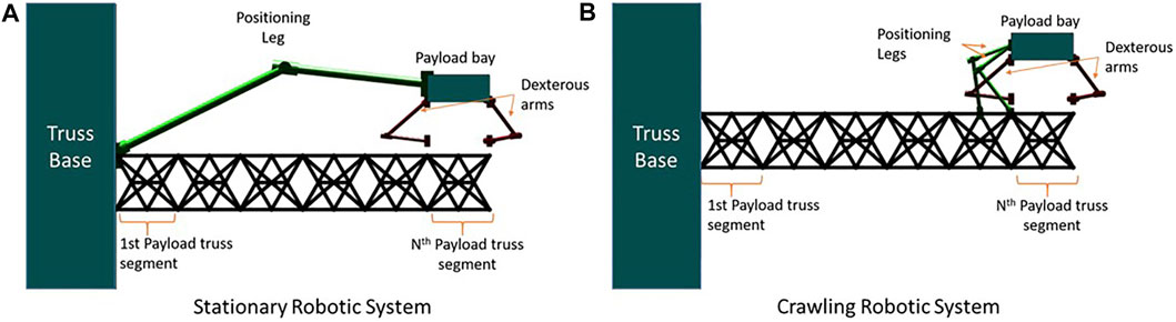
FIGURE 1. (A) Stationary robotic system (B) Crawling robotic system.
The crawling robotic system uses the same payload bay and dexterous arms as the stationary robotic system, see Figure 1B. Two positioning legs move the payload bay into place rather than the one stationary leg. The two positioning legs move from mounting point to mounting point, located at the edges of the truss segments. The positioning legs move one at a time, ensuring the robotic system remains attached to the assembled structure at all times. They work together to move the payload bay into position.
Figure 2 shows the major components of the simulation starting with defining the truss requirements. These are the structural design parameters that drive the completed structure, e.g., the total length, required natural frequency, and the allowable maximum deflection. These are the driving design parameters which can be used to calculate the height and width of the final truss. From there the truss can be divided into a number of different equal length segments.
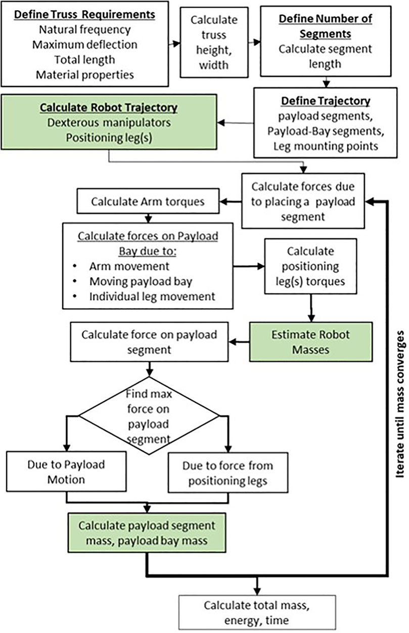
FIGURE 2. Simulation flow diagram.
Once the number and size of each truss pieces has been calculated, the trajectory for each piece is determined, see Section 4 for details. In addition to defining the trajectory of the truss segments, the payload bay location and the trajectory of the feet which attach to footholds are calculated for the entire assembly simulation. This is done using a trapezoidal trajectory design which calculates the position, the velocity, and acceleration for each component. Using this information, the Cartesian trajectory for each end-effector is calculated, see Eqs 1, 2. F is the force-torque vector of the task, which is acting on an end-effector. X is the Cartesian coordinate vector representing position and orientation for the manipulator with a Cartesian mass matrix Mx. Vx is the vector of velocity terms and Gx is the gravity terms (Craig (2005)).
The joint torques, τ, are related to the force applied at the end-effector via the Jacobian, J(θ). The Jacobian is a function of the instantaneous geometry and thus changes as a function of time.
The joint trajectory for each manipulator is based on the desired end-effector position, velocity, and acceleration. An optimization is done to ensure the joint angles will result in the desired end-effector position while minimizing the movement from the previous time-step. This ensures a smooth motion. As the complexity of the robot manipulators increases, the complexity in calculating the joint trajectory can also increase. For a redundant manipulator constraints can be added to avoid singularities, collisions, and even minimize base torques. The shaded boxes in Figure 2 indicate an optimization is being done, such as calculating the manipulator trajectory in order to minimize the change in joint angles.
Joint torques are calculated based on the joint trajectories, which are used to estimate the mass of each manipulator. The mass estimation relation was found using heuristics and a constrained optimization scheme to find the thickness of each link length, details are presented in Section 5. Once the mass of each manipulator is estimated then the force on each truss segment and the force on the truss assembly are able to be calculated.
The mass of the truss structured is then calculated to survive the assembly forces placed on it by the robotic system. An iterative process is required as the joint torques are a function of the mass of each truss segment and the manipulator mass. This simulation results in the total system mass, mechanical energy, and assembly time for each robotic system as they assemble the same linear truss.
The total maneuver time is the duration it takes to assemble the truss and then return to the robot’s original starting position. This estimate is limited to the time it takes for the robot manipulators to perform large maneuvers. Other motions such as grasping and verifying all connections are not included. These are highly dependent on the end-effector and sensors which are assumed to be the same for both robotic systems.
The total maneuver time is dependent on the path of each truss segment, motion of the payload bay, and the motion of each positioning leg. In order to calculate how long the assembly takes the assembly process must first be defined, including where and how each truss segment is placed. The total maneuver time is driven by the distance, maximum velocities, and the maximum accelerations, all of which must be defined for both the crawling and stationary systems.
This simulation uses a simple trapezoidal trajectory for moving each truss segment and the payload bay from one position to another. The joint trajectory for each manipulator is calculated based on the movement of the grasping locations, which can be calculated based on the geometry once the trajectory for the truss segment, and the payload bay have been defined. The total assembly process is made up of a series of these trapezoidal trajectories being executed sequentially.
Each trapezoidal trajectory is defined by three segments: the first segment is defined by having a constant acceleration, the second segment is one of constant velocity, and finally the third segment has a constant deceleration. The length of the constant velocity section depends on the maximum allowed velocity, total distance traveled, and the magnitude of the acceleration.
This simulation assumes that the initial and final velocity for each trajectory is zero. Not only does this simplify path planning, this allows the system time to confirm that the motion has been completed as expected before moving onto the next trajectory.
The use of a trapezoidal trajectory allows the position and orientation to be calculated along the entire path. The trajectory design of the each truss segment depends on the location of the payload bay relative to the final position. Here, the payload bay is placed such that a truss segment can be lowered down vertically into its final position. The robotic manipulators grasp the payload bay and the truss segments; these trapezoidal trajectories not only provides the end-effector location as a function of time but also the velocity and acceleration.
The payload bay and truss segments have the same velocity and acceleration for each of the two robotic systems. In both systems the positioning leg(s) move the payload bay into place and the dexterous arms lower the truss segments in the same amount of time. Defining the payload bay motion and the dexterous arm motion independent of the robot type results in the crawling robot always having a longer total maneuvering time than the stationary robotic system due to the additional maneuvers required to relocate the positioning legs.
Mass is often used as a performance metric for space systems. Here, the total mass of the system consists of the mass of each of the manipulators, the total mass of all the truss segments, and the mass of the payload bay. Each of these is dependent on the length and number of the truss segments. The following subsections provide details for estimating the mass of each of these components.
The mass of each manipulator is calculated by estimating the mass of the motors, harmonic gearing, and the structure. It should be noted that these manipulators are sized based on the joint torques necessary to accomplish each trajectory in the space environment, they are not designed to operate in earth-gravity. The manipulators here are sized to specifically accomplish the defined assembly task; this represents a lower-bound mass estimate which will be used for comparison purposes.
The motor mass estimation is found using a heuristic based on commercially available high end brushless DC motors, similar to ones used for space robotics. Eq. 3 is the motor mass estimation depending on the required output torque, T in Newton-meters, and the motor speed, S in thousands of revolutions per minute (kRPM), for small and large motors. Details on this mass estimate relation can be found in (McBryan (2018)).
Each joint is assumed to use harmonic gearing to reduce the required motor torques; this example uses 160:1 for simplicity. Other single stage gearing will have a similar mass relationship. The gear ratio can be optimized in order to minimize the total manipulator mass; though each is dependent on the output required output torque which is a function of the truss segment trajectory and size. Eq. 4 shows the mass relationship between the rated output torque, To, from the harmonic gearing to the harmonic mass. The total actuator mass for each manipulator is a sum of the motor mass and the harmonic mass.
The structural mass of each manipulator link is added to complete the manipulator mass estimation. The manipulator links are sized to ensure the tip deflection is within an acceptable range when the maximum expected force is applied; ensuring any deflection from the link lengths is within an acceptable bounds. Figure 3 shows the outstretched manipulator in one of the worse case poses. The link lengths must be sized to handle a maximum force and torque without resulting in too large of a deflection. The expected force, P, and moment, M, are based on the truss segment mass and acceleration. A constrained optimization to minimize the total structural mass while ensuring the maximum deflection constraint is performed, (Cheng et al. (2015)).
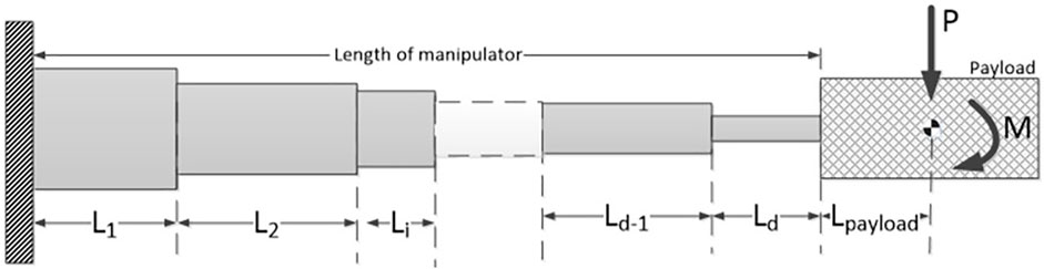
FIGURE 3. Manipulator as a cantilever beam for mass estimation of each link.
Rectangular truss segments are attached together to form the final linear truss. Each of these segments are identical in length, width, and height. The length of the truss segments depends on the assembled truss length and the number of segments it is divided into. The height and the width are identical, forming a square base, and are calculated based on the desired frequency of the completed truss.
Mikulas et al. (2006) shows the impact of the truss diameter on structural mass, stiffness, and strength, see Figure 4. The moment of inertia is a function of the longeron diameter, d, and the total diameter, D. The total diameter is used to define the height and width of the truss. Eq. 5 shows the moment of inertia of the truss as it relates to the total diameter and the total area in the longerons, Atotal. This is found using the parallel axis theorem, and assumes that the diameter of the longeron is much smaller than the total diameter, D, and thus the higher order terms are neglected.
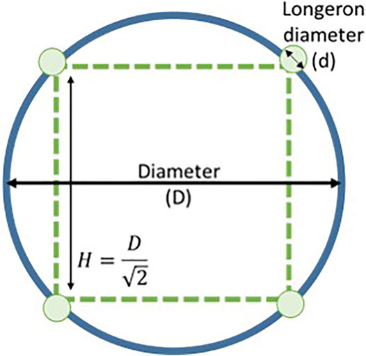
FIGURE 4. Inscribed truss segment profile used in estimating the frequency.
The natural frequency, f, is calculated from the moment of inertia, I, the length of the truss, L, the total mass, M, and the boundary conditions. The boundary conditions are accounted for in α, which is 22.4 based on the free-free boundary conditions (Blevins (2015)).
A longer truss must have a greater height in order to maintain the same frequency as a shorter truss. The final assembled truss in this simulation was designed for a minimum natural frequency of 5 Hz. This is for the truss, acting as a beam, without any payloads or other masses acting on it. In addition, this method ignores the effect of any strings or diagonal members which maybe present in the truss.
The total truss mass is the sum of every longeron, which is a function of the number of longerons, area of the longerons, Alongeron, and the density, ρ. Eq. 7 shows the relationship between the total area, Atotal, and the total mass, Mtotal.
Combing Eqs 5–7, it becomes clear that the total diameter is a function of the density, length, and desired stiffness, see Eq. 8. Geometric constraints then provides the height and the width of the truss based on the desired requirement.
It is assumed that the outer diameter of each longeron is the same for all the truss segments. Should the robot need to grasp the individual longerons this will simplify the interaction. The inner diameters are sized such that the truss will not buckle if a truss segment hits the end. Typically the robotic system will decelerate each truss segment and mate it to the truss with very little force. However, the truss itself should be sized to withstand an impact in case the robotic system fails and the truss segment collides with the truss. Safety precautions should be put in place to ensure this will not occur and testing should be done to verify that it cannot occur.
The final part of the mass estimation is to include a measure of the attachment hardware. More hardware and connection points are needed as a truss is divided into more segments. A 5% mass penalty is included with each additional segment to account for this hardware. The final truss design is based on the desired frequency of the final truss, sized so that it will not buckle if a truss segment is pushed into it at the maximum allowable acceleration, and the mass-penalized for requiring additional attachment hardware.
The payload bay is a simple rectangular frame that contains all the truss segments before they are placed. It is assumed the truss segments are stored in a non-deployed state which allows them to collapse to 1/10 of their deployed state. The payload bay length and width are assumed to be 10% bigger than that of a single payload segment, and the height is sized to hold all the non-deployed truss segments in their collapsed states. The dexterous arms and positioning legs are connected to the payload bay.
The first case study looks at a 20 m linear truss; 20 m represents a large ISA satellite such as the iSAT design (Mukherjee et al. (2019)). This truss is made up of rectangular truss segments with a desired stiffness of 5 Hz, which results in each truss segment having a height and width of 0.45 m. Both a Stationary robotic system and a Crawling robotic system are designed to assemble this truss. As described above, trapezoidal trajectories are used to define the trajectory for each truss segment, and here each truss segment is accelerated at 10 mm/s2.
As expected the Crawling robotic system takes more time to complete the assembly than the stationary robotic system. The two positioning legs must relocate whereas the stationary system does not, see Figure 5. This time estimate only includes the large motions for the dexterous arms and legs, such as lowering the truss segment into position, moving the payload bay, and relocating the legs. The additional time to actually grasp the truss segments, release the segments, and or verify any mechanical or electrical connections are not included in this estimate. The speed at which those tasks can be accomplished with depend on the sensors, computing power, and software efficiency. With these additional considerations, the time difference between the robotic systems will only increase.
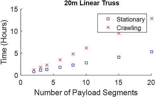
FIGURE 5. Time to complete large motions for the assembly of a 20 m linear truss.
Figure 6 shows the average mass for each truss segment. As expected, the larger truss segments pieces are individually heavier; however there are fewer of them. The mass for each truss segment is not identical; there is some variation depending on the location along the truss. The furthest truss segment does not need to withstand large moments like the ones closest to the base structure.
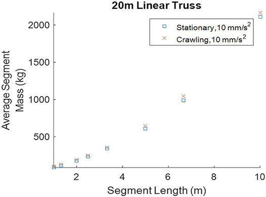
FIGURE 6. Average truss segment mass for individual pieces of a 20 m linear truss.
A detailed look at the mass of the stationary robotic system is found in Figure 7. Figure 7A shows the total truss mass as the number of segments increase. The total truss length is fixed at 20 m; as the number of truss segments increases the length of each piece decreases. As the number of pieces increases, more connecting hardware is required. This is reflected in the 5% mass penalty.
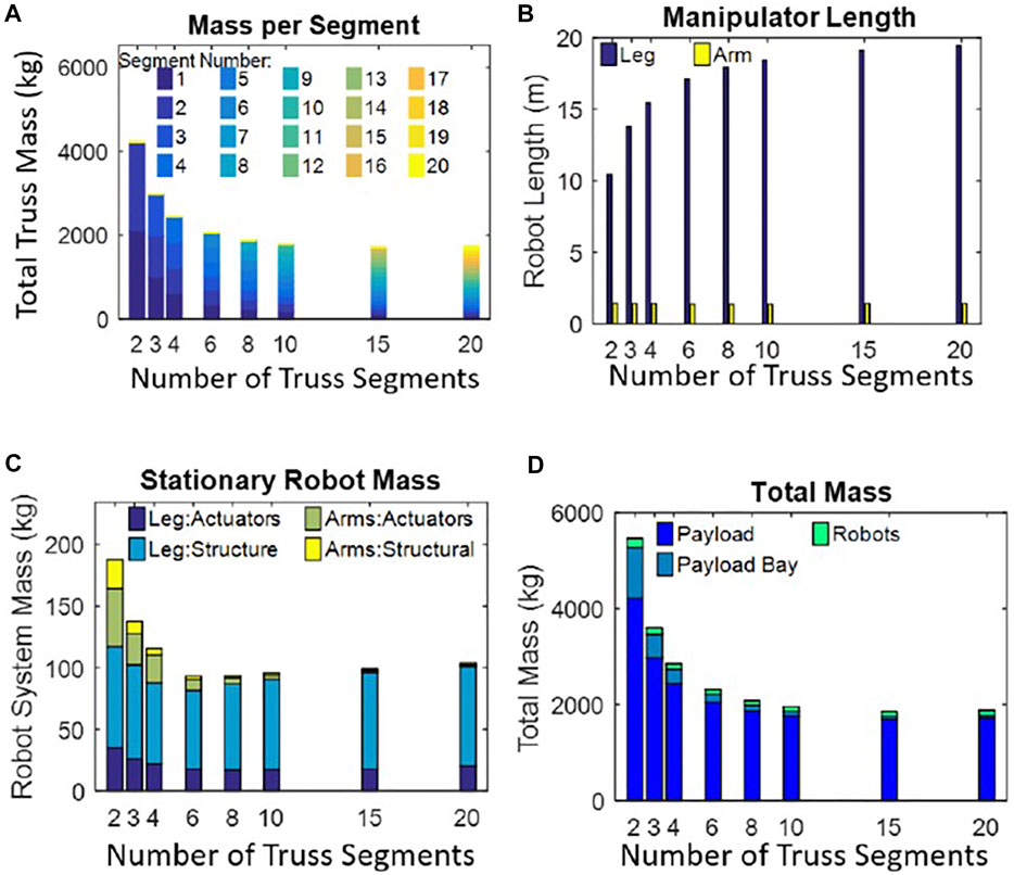
FIGURE 7. Stationary Robotic system mass analysis when assembling a 20 m linear truss: (A) Total truss mass for an assembled 20 m linear truss; (B) length of each of the two dexterous arms and the single positioning leg; (C) total robotic mass; and, (D) total system mass.
The stationary positioning leg moves the payload bay into the correct location above the center of each truss piece being placed. This allows the dexterous arms to vertically lower a truss piece into place. As the truss segments become shorter and more numerous the center of the final truss piece is further from the truss base. As such, the length of the positioning leg increases as the number of segments increases, see Figure 7B. This increase in length results in higher moments even when the individual truss segments are lower mass. In all of these simulations the length of the positioning leg is greater than 10 m.
Truss segments are lowered into place by the dexterous arms; the distance the end-effectors move is dependent on the truss segment height. The height is based on the total truss length and required stiffness; the height does not vary depending on the number of segments. The lengths of the dexterous arms are a function of the height of each truss segment rather than the truss segment length. However, the motor and structural mass of each dexterous arm is influenced by the truss segment mass which is dependent on the segment length. The dexterous arms move the individual truss pieces and as the mass of each piece decreases the required joint torques also decreases. A reduction in the truss segment mass results in a reduction in both the actuator and the structural mass in both the dexterous arms.
The total robotic mass is the combination of the two dexterous arms and the positioning leg, see Figure 7C. As the number of truss segments increase, the dexterous arms become lighter; requiring smaller actuators, and a reduction in the structural mass. Conversely, the positioning leg becomes longer resulting in a higher structural mass. Here, the mass of the robotic system is driven by the structural mass of the positioning leg. Assembling the truss with six truss segments, each 3.3 m, results in the minimum robotic system mass. It should be noted that this robotic system is specifically designed to only work in the space environment to perform these assembly tasks.
Combining the robot mass, truss mass, and the payload bay mass, results in the total mass, see Figure 7D. It is clear that the total mass is driven by the truss mass and that the robot system is only a small fraction. This is a case where continuing to minimize the mass of the robotic system alone may not have a major impact on the system.
Figure 8 shows the detailed mass analysis for a crawling robot. Like the stationary robotic system the truss segments decrease in mass as the number of truss segments increase Figure 8A. Unlike the stationary robotic system, as the number of payload segments increase the length of the positioning legs decrease, Figure 8B. The length of each of the positioning legs is driven by how far it must reach when positioning the payload bay and when taking a step to relocate to the next foothold. Each step is the entire length of a truss segment; each leg moves one at a time and releases their grasp on the foothold at one end of the truss and moves to the other end and grasps onto the next foothold. The decrease in the length of the positioning legs results in the mass of the robotic system decreasing as the number of payload segments increase. Not only does the structural mass of the positioning legs decrease with length but the actuator masses do as well.
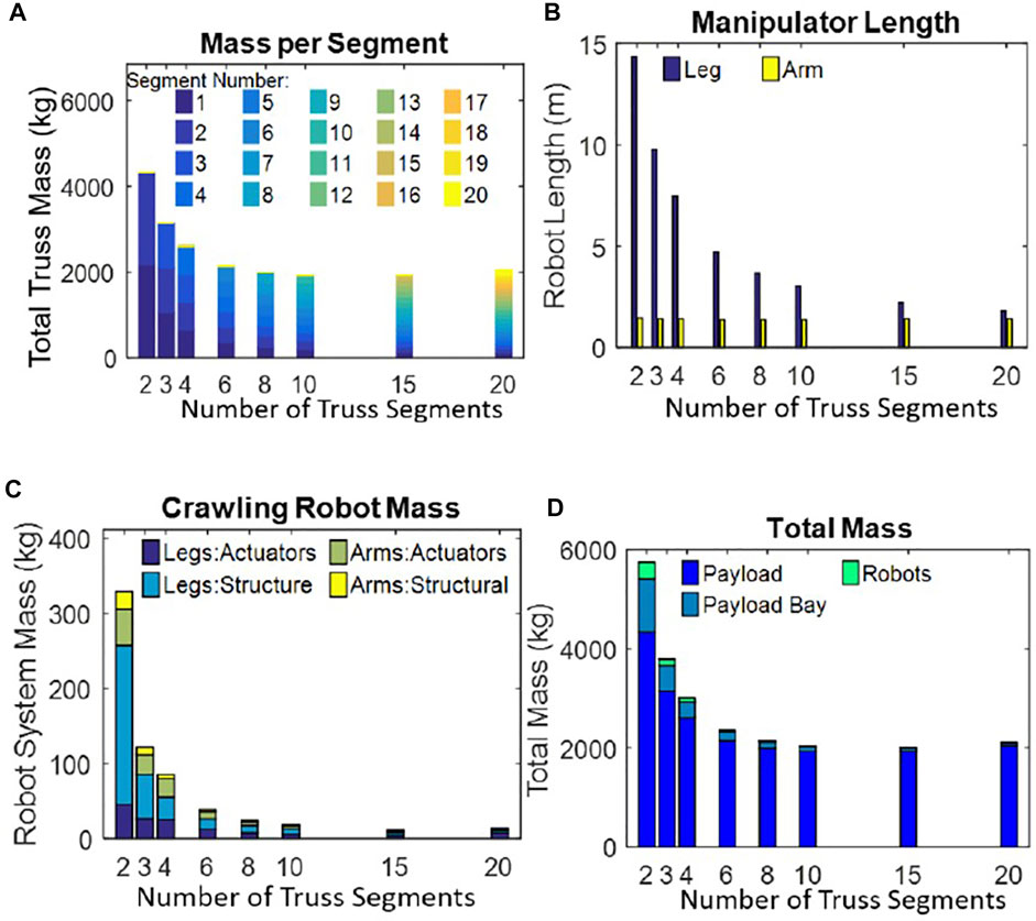
FIGURE 8. Crawling Robotic system mass analysis when assembling a 20 m linear truss: (A) Total truss mass for an assembled 20 m linear truss; (B) length of each of the two dexterous arms and the dual positioning legs; (C) total robotic mass for all manipulators; and, (D) the total system mass.
The dexterous arms have the same design constraints as that of the stationary robotic system; the mass and length of the dexterous arms are based on the truss segments and their design is independent of the type of robotic system used. The reduction in the overall robot system mass is from the reduced size of the positioning legs, Figure 8C.
Figure 8D shows that the total system mass is driven by the truss mass. This is even clearer here than in the case of the Stationary robot; the robotic mass is a very small percentage of the total overall mass. In this case, in order to truly make a mass efficient design one should try and reduce the truss mass and then the robot mass.
This section compares the Stationary robotic system to the Crawling system as they are each designed to assemble identical 20 m trusses. Figure 9A shows the difference in the positioning leg lengths. The Stationary positioning leg must reach further as the segment length decreases, whereas the crawling legs become shorter as they are required to take smaller steps. The length of the positioning leg(s) is greatly dependent on the segment length and on the type of robotic system.
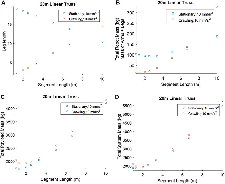
FIGURE 9. Crawling robotic versus Stationary robotic system mass analysis when assembling a 20 m linear truss: (A) length of the positioning legs; (B) total robotic mass for all manipulators; (C) total truss mass for an assembled 20 m linear truss; and (D) describes the total system mass.
As the length of the truss segments increases, the robot mass also increases and drives the mass of the actuators for all the manipulators. Figure 9C shows the mass of each robotic system. If the truss is assembled using two large truss segments then stationary robotic system has the lower robot mass. As the number of truss segments increases the crawling system becomes the more mass efficient option.
The most mass effective robotic system is the crawling robot, designed to take small steps and move small truss segments. However, Figure 9B shows the mass comparison of two assembled trusses. Unlike the Stationary robot, the Crawling robot moves along the truss which results in the truss carrying forces and high moments. The Crawling robot places additional forces on the truss from relocating each leg. The truss assembly must be able to handle all these forces as they occur at the multiple footholds along the truss length. The Crawling robot results in higher forces and moments at the truss base, which results in a higher truss mass than the Stationary robot.
Despite having a lower robot mass, the Crawling robotic system has a higher total system mass than the Stationary robotic system, Figure 9D. The forces on the truss from the crawling robot results in a higher truss mass and, in this scenario, a higher total mass.
This first study case focused on assembling a 20 m linear truss in order to compare a Stationary robot with a Crawling robot. There are many ways of comparing the two systems; time, robot length, robot mass, truss mass, and total system mass, etc. Which robotic system is preferable depends on the driving performance criteria; there was no single robotic system which was overall better. However, it is clear that a robotic ISA system should be viewed as a system; not as a robotic system and the assembly structure. A change in the length or mass of the truss segments will greatly influence the robotic design. The second case study expands this study to look at various assembled truss lengths.
Rather than focus on a single 20 m truss this study includes a 10 m and 50 m truss. Each of these trusses are sized using the methods described above. In order to maintain the same stiffness the 50 m linear truss requires a much taller truss than the 10 and 20 m. The additional height requirement results in a significantly more massive system. Similarly, the 10 m truss has a significantly lower mass than the 20 m truss.
Figure 10 shows the height and the mass of the different length trusses. As the length of each truss segment decreases the number of truss segments must increase. A 5% mass penalty is included for each additional segment in order to account for the increase in attachment hardware and mechanisms that would be necessary. This mass penalty is the reason why the truss mass does not continue to decrease as the segment lengths decrease. Each of the different length truss has an a point at which using more shorter truss segments results in a heavier truss.
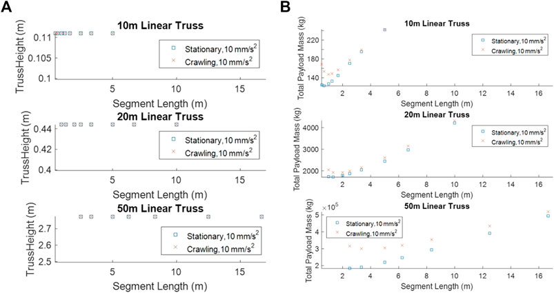
FIGURE 10. Height (A) and mass (B) of the payload, individual truss segment, as a function for the individual truss segment length and robot type for different assembled truss lengths.
Except for the case where each truss is assembled from two segments, the Crawling robot is always less massive than the Stationary robot, see Figure 11. The Stationary robotic system is only more mass efficient when a few large truss segments are used to complete the assembly. The mass of the Crawling robot decreases as more truss segments are used.
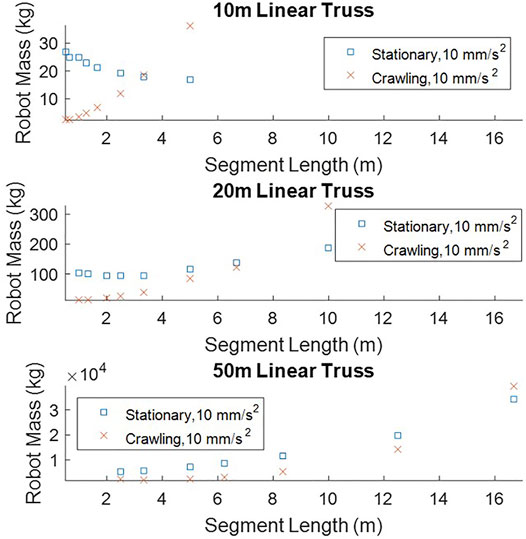
FIGURE 11. Total robot mass for assembling a 10, 20, or a 50 m truss.
The robot mass is not the only consideration when optimizing a robotic ISA system; the total system mass should always be considered as well. This becomes clear in Figure 12. There are times when the mass difference between the two robotic systems mass is very small, particularly with the 10 m truss where the Crawling robot is slightly more mass efficient. This occurs when the additional structural mass required for Crawling robot is less than the mass difference of the two robotic systems.
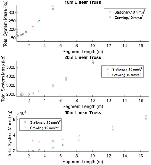
FIGURE 12. Total system mass for assembling a 10, 20, or a 50 m truss.
The Crawling robotic system requires a higher truss mass. This is due to the fact that the crawling robot is applying forces along the length truss rather than at the truss base, as the Stationary robot does. These forces are not just from the walking motion but every motion; keeping the payload bay steady as the dexterous arms perform assemble new truss segments and from moving the payload bay into place. These required tasks are also done by the stationary robot. The main difference is the location at which the robots are applying forces and moments to the truss.
As the total truss length increases the entire system becomes much heavier. The height and width of each truss segment must increase to maintain the same required structural frequency. In addition, the outer diameter and thickness must increase in order to meet the buckling requirements. All of these factors results in a large mass increase as the assembled truss increases in length. Moving these larger truss segments drives the mass up for both robotic systems.
The two previous cases show that a Crawling system has the lower robot mass but a higher truss mass. This typically results in an overall heavier system. The increase in the truss mass is a direct result of applying forces along the truss rather than just at the base of the truss.
The forces and moments required to complete the assembly are not only highly dependent on size of the truss but also on the chosen payload trajectory. Reducing the payload acceleration will reduce the joint torques required to perform the maneuver and thus decrease the forces being applied to the truss by each of the robotic systems. This case study focuses on how the overall system changes when the payload acceleration is reduced from 10 mm/s2 to 2.5 mm/s2.
Figure 13 shows the robot mass for each robot type for the different accelerations. It is clear that reducing the acceleration will reduce the robot mass. This difference is most notable when the assembled truss is composed of only a few large truss segments.
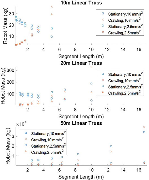
FIGURE 13. Comparison of the total robot mass for assembling a 10, 20, or a 50 m truss at a payload acceleration of 10 mm/s2 and 2.5 mm/s2.
Regardless of the robotic system used, reducing the truss segment acceleration will reduce the mass of the truss. The truss is sized to ensure it does not buckle if a truss segment collides with the truss assembly. Reducing the allowable maximum acceleration will reduce the buckling criteria on the truss itself allowing for smaller truss pieces, see Figure 14. While the Crawling robot still requires a heavier truss the difference between the truss mass for the two robotic systems is significantly less at the lower acceleration.
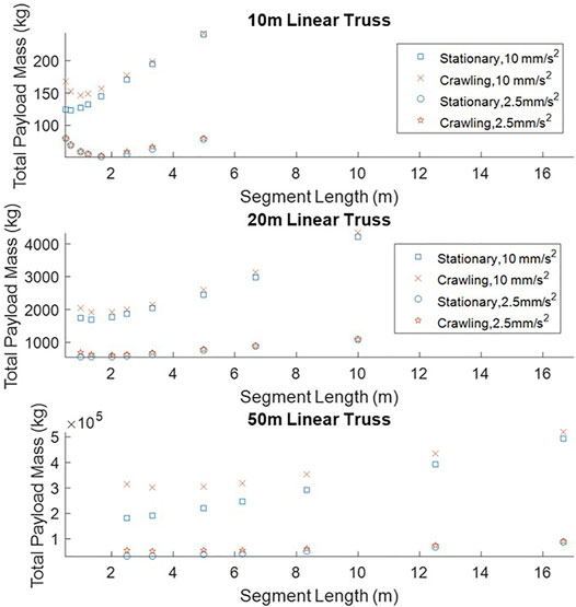
FIGURE 14. Comparison of the total truss mass for assembling a 10, 20, or a 50 m truss at a payload acceleration of 10 mm/s2 and 2.5 mm/s2.
As before, the system mass is comprised of the total truss mass, the payload bay mass, and robot mass. Previous cases showed that the Crawling robot requires a heavier truss, resulting in a heavier overall system. At a reduced acceleration the increase in the truss mass is greatly reduced. Figure 15 shows the system mass for all three lengths of trusses as they are assembled at the nominal and reduced accelerations Figure 15A.
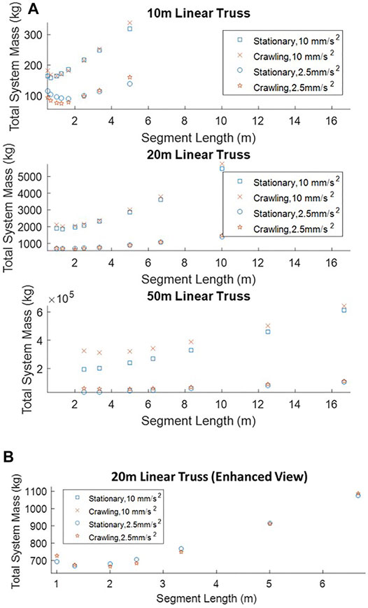
FIGURE 15. (A) Comparison of the total system mass for assembling a 10, 20, or a 50 m truss at a payload acceleration of 10 mm/s2 and 2.5 mm/s2 (B) Enhanced view of the 20 m linear truss system for segment lengths between 1 and 7 m.
At the reduced acceleration the Crawling system is now the more mass efficient system for the shorter 10 m truss. Figure 15B shows an enhanced view of the 20 m truss. This shows that both robotic systems are very close in mass and which one is more mass efficient depends on the individual truss segment length. For longer trusses (
There are many variables which will influence a robotic ISA system, here the effects of changing the length of the truss, the number of pieces, and the acceleration were examined. Each of these variables has a large impact on both a Crawling and Stationary robotic system. There are many more variables which will influence the system such as the number of truss segments being carried at a time, the trajectory of each manipulator, and the force to attach the truss segments, etc. All of these variables will influence each category of robots differently.
This study was done with planar 3° of freedom (DOF) manipulators whereas moving to a non-planar case would allow full 7-DOF redundant manipulators, as would typically be used in an ISA operation. Non-planar cases also increases the number of variables and allow out-of-plane forces to be examined. This would also allow a full truss system to be analyzed, including foot placement and force distribution between manipulators.
Mass efficiency is a large factor in any space system. However, it is not the only factor; time, size, and power are also major factors in a well-designed space system. Reducing the acceleration was shown to reduce the mass of the system, however, it will also increase the assembly time. Defining the task should also include defining how the system is evaluated. In order to truly compare two robotic systems the task must be well-defined; this includes defining the final structure, each assembled pieces, and how the assembly is done.
This study focused on assembling planar trusses in order to compare Stationary and Crawling robotic systems. From the limited cases presented, it is clear that a robotic in-space assembly system, and the structure should be viewed as a single system. Here, it was shown that, in terms of robotics, the Crawling robot is a lighter-weight option than a rigidly mounted Stationary robot. However, the Crawling robot also requires the truss to be able to handle higher forces and torques; resulting in a higher overall system mass. Examining the structure or robot alone does not provide enough insight into the overall system. Robotic ISA occurs in a highly structured and known environment, where the robot and the structure are both being designed, and built by humans; as such both aspects can be controlled.
The original contributions presented in the study are included in the article/Supplementary Material, further inquiries can be directed to the corresponding author.
KM contributed to conception and design of the study, wrote the simulation utilize existing robotic toolboxes, analyzed, and wrote the results. All authors contributed to manuscript revision, read, and approved the submitted version.
The authors declare that the research was conducted in the absence of any commercial or financial relationships that could be construed as a potential conflict of interest.
All claims expressed in this article are solely those of the authors and do not necessarily represent those of their affiliated organizations, or those of the publisher, the editors and the reviewers. Any product that may be evaluated in this article, or claim that may be made by its manufacturer, is not guaranteed or endorsed by the publisher.
Thank you for the contributions of my colleagues at the Naval Research Laboratory and at NASA Langley for aiding in the efforts.
Belvin, W. K., Doggett, W. R., Watson, J. J., Dorsey, J. T., Warren, J. E., Jones, T. C., et al. (2016). “In-space Structural Assembly: Applications and Technology,” in 3rd AIAA Spacecraft Structures Conference. San Diego, California, 2163. doi:10.2514/6.2016-2163
Cheng, G. H., Younis, A., Haji Hajikolaei, K., and Gary Wang, G. (2015). Trust Region Based Mode Pursuing Sampling Method for Global Optimization of High Dimensional Design Problems. J. Mech. Des. 137, 021407. doi:10.1115/1.4029219
Corke, P. I. (1996). A Robotics Toolbox for Matlab. IEEE Robot. Automat. Mag. 3, 24–32. doi:10.1109/100.486658
Craig, J. J. (2005). "Introduction to Robotics: Mechanics and Control, 3/E," in Addison-Wesley Series in Electrical and Computer Engineering: Control Engineering. Upper Saddle River, NJ: Pearson/Prentice Hall.
Doggett, W. R., Dorsey, J., Teter, J., Paddock, D., Jones, T., Komendera, E. E., et al. (2018). “Persistent Assets in Zero-G and on Planetary Surfaces: Enabled by Modular Technology and Robotic Operations,” in 2018 AIAA SPACE and Astronautics Forum and Exposition, Orlando, FL, 17-19 September 2018, 5305. doi:10.2514/6.2018-5305
Komendera, E. E., and Dorsey, J. (2017). “Initial Validation of Robotic Operations for In-Space Assembly of a Large Solar Electric Propulsion Transport Vehicle,” in AIAA SPACE and Astronautics Forum and Exposition. Orlando, FL, 5248. doi:10.2514/6.2017-5248
Lee, N., Backes, P., Burdick, J., Pellegrino, S., Fuller, C., Hogstrom, K., et al. (2016). Architecture for In-Space Robotic Assembly of a Modular Space Telescope. J. Astron. Telesc. Instrum. Syst. 2, 041207. doi:10.1117/1.jatis.2.4.041207
McBryan, K. (2020). “Comparison between Stationary and Crawling Multi-Arm Robotics for In-Space Assembly,” in 2020 IEEE/RSJ International Conference on Intelligent Robots and Systems (Las Vegas, NVIEEE). doi:10.1109/iros45743.2020.9341141
McBryan, K. M. (2018). Task-Based Optimization of Multi-Arm Space Robotics. Ph.D. thesis. College Park: University of Maryland.
Mikulas, M. M., Collins, T. J., Doggett, W., Dorsey, J., and Watson, J. (2006). Truss Performance and Packaging Metrics. AIP Conf. Proc. (Aip) 813, 1000–1009. doi:10.1063/1.2169281
Mukherjee, T., Siegler, N., and Thronson, H. (2019). The Future of Space Astronomy Will Be Built: Results from the In-Space Astronomical Telescope (iSAT) Assembly Design Study. Pasadena, CA.
NASA (2011). International Space Station Assembly - Past Flights. Availbale at: https://www.nasa.gov/mission_pages/station/structure/iss_assembly.html. (Accessed March 3, 2021).
Keywords: walking, crawling, multi-arm, assembly, in-space assembly, robot, space
Citation: McBryan K (2022) Comparing Multi-Arm Robotics for In-Space Assembly. Front. Space Technol. 3:702614. doi: 10.3389/frspt.2022.702614
Received: 29 April 2021; Accepted: 20 January 2022;
Published: 01 April 2022.
Edited by:
Craig R. Carignan, University of Maryland, United StatesReviewed by:
Koki Ho, Georgia Institute of Technology, United StatesThis work is authored by Katherine McBryan on behalf of the U.S. Government and as regards Dr. McBryan and the U.S Government, is not subject to copyright protection in the United States. Foreign and other copyrights may apply. This is an open-access article distributed under the terms of the Creative Commons Attribution License (CC BY). The use, distribution or reproduction in other forums is permitted, provided the original author(s) and the copyright owner(s) are credited and that the original publication in this journal is cited, in accordance with accepted academic practice. No use, distribution or reproduction is permitted which does not comply with these terms.
*Correspondence: Katherine McBryan, a2F0aGVyaW5lLm1jYnJ5YW5AbnJsLm5hdnkubWls
Disclaimer: All claims expressed in this article are solely those of the authors and do not necessarily represent those of their affiliated organizations, or those of the publisher, the editors and the reviewers. Any product that may be evaluated in this article or claim that may be made by its manufacturer is not guaranteed or endorsed by the publisher.
Research integrity at Frontiers
Learn more about the work of our research integrity team to safeguard the quality of each article we publish.