 Robert T. Schwarz
 Dirk Giggenbach
 Marcus T. Knopp
 Andreas Knopp1
- 1Chair of Signal Processing, Institute of Information Technology, Bundeswehr University Munich, Neubiberg, Germany
- 2Satellite Networks Department, Institute of Communications and Navigation, German Aerospace Center (DLR e.V.), Wessling, Germany
- 3German Space Operations Center (GSOC), Space Operations and Astronaut Training, German Aerospace Center (DLR e. V.), Wessling, Germany
Future exploration of our planetary system relies on the Moon as a base and stepping stone to other planets. A high-rate data connection to this celestial body is, therefore, imperative. Free-space optical (FSO) communications will enable continuous broadband connectivity to Earth. Currently pursued concepts incorporate data relay satellites orbiting the Moon, where each individual satellite terminal has to overcome the lunar distance facing restraints on telescope apertures and on beam pointing and tracking accuracies. We propose a concept of one dedicated link originating from a robotic telescope station installed on the lunar surface. We study the conceptual architecture of such an FSO ground node at the lunar surface with a spotlight on the link design at the physical layer. In particular, we increase the FSO channel capacity through multiple transmission- and receiving-apertures. Our findings encourage the application of the Line-of-Sight (LOS) multiple-input multiple-output (MIMO) technology to FSO communications at large link distances typically coming along with space missions, as thereby the maximum MIMO capacity can be achieved. Directing our study on the link geometry such connections seem technically feasible at relatively low system complexity with the receivers located at a single site and the transmitters only few meters apart.
1 Introduction
With the beginning of the current decade astronautical and robotic spaceflight is increasingly heading for the Moon and Mars. Setting foot on Mars is the new long-term goal of international spaceflight. In this context, the Moon is seen by most space-faring nations as an important intermediate step for an astronautical mission to Mars. NASA’s primary goal is to land American astronauts on the lunar surface by the mid-2020s (Evans et al., 2020). The planned Gateway, a temporary manned station in lunar orbit, is an important milestone toward that goal (Fong, 2018), as well as its Commercial Lunar Payload Services Program (CLPS), where NASA will solicit rides for its payloads using task orders (Bussey et al., 2019). Within ESA, activities in this regard are underway under the keyword Moon Village aiming at a base on the lunar surface (Woerner and Foing, 2016). JAXA’s plans go along similar lines (Matsumoto et al., 2006). Both China and India have initiated lunar exploration programs and part successfully launched robotic missions to the Moon’s surface (Li et al., 2019; Goswami, 2020).
Taking this increased interest in missions to the Moon for granted, we argue that, to be successful in the long term, lunar exploration requires a high-capacity communication link to Earth. Sensor technology of scientific experiments in particular has improved significantly in recent decades and transmission of raw data requires ever more bandwidth. The main challenges in this respect are the long link range of close to 400,000 km and the tight constraints usually put on the size, weight and power (SWaP) of the spacecraft. Microwave radio relay at X-band carrier frequencies is the classic way to transmit signals from the Moon to Earth-based receiving stations bringing the advantage of reliable, weather-independent transmissions, but also the disadvantage of high fee-space loss necessitating large dishes at the ground antennas to reach a decent link-budget. Moreover, X-band transmissions are severely limited in capacity. Hence, upcoming missions turn to Ku- and Ka-band offering larger bandwidths at the downside of greater susceptibility to atmospheric disturbances (Wells, 2009).
Free-space optical (FSO) communications at carrier frequencies of several hundred terahertz is also affected by the atmosphere, but comes with the advantage of significantly higher bandwidths and drastically lower free-space loss (FSL) than radio frequency (RF) communications (Agrawal, 2002; Hemmati, 2006; Henniger and Wilfert, 2010; Giggenbach et al., 2018). Hence, laser-based communication terminals (LCTs) are compact, lightweight and low-power alternatives to classic RF equipment and have demonstrated their performance at the lunar distance (Boroson et al., 2014). Within the Artemis program NASA is going to advance this technology for applications in human spaceflight (Seas et al., 2018) (2018), such that requirements on data transmissions for a link from the Moon to the Earth are currently controverted within the community (Araki, 2021).
In terrestrial radio transmission multiple antenna systems are a common method to achieve higher received field strengths and higher data rates by spatial diversity (Mietzner et al., 2009). While most implementations are based on multipath propagation of the signals (Jensen and Wallace, 2004), spatial multiplexing by well-designed Line-of-Sight (LOS) multiple-input multiple-output (MIMO) channels has been shown to provide the maximum possible capacities (Sarris and Nix, 2006). The latter has been successfully applied to space-communications gaining performance in terms of signal throughput in both the feeder link and the multiuser downlink of multibeam satellites, as well as satellite broadcast systems (Schwarz et al., 2008, 2019). However, such transmissions are prone to particular design constraints like exact antenna spacings and precoding of the transmit signals.
The MIMO technology has already been applied to FSO communications, where possible FSO system architectures can be grouped in coherent or non-coherent transmitter (Tx)-receiver (Rx) designs (Caplan, 2008). Research findings on non-coherent system designs applying intensity modulation (IM) with direct detection (DD) and related modulation techniques such as on-off keying (OOK), pulse position modulation (PPM) or Sub-carrier Intensity Modulation (SIM) concern performance analyses of either different fading conditions (Bayaki et al., 2009; Zhang et al., 2015) or of different modulation schemes (Ghassemlooy et al., 2009; Israr et al., 2019). In those systems, the application of MIMO is mainly motivated to combat fading effects due to atmospheric turbulence and scintillations (Wilson et al., 2005; Frigyes et al., 2012). The aim is to increase the availability and reliability of the free-space communication link by multipath propagation. For short-range terrestrial FSO transmissions, typically, multiple lasers and multiple photo-detectors can also provide a spatial diversity gain (Hajjarian et al., 2009; Deng et al., 2013).
In this paper we aim at a coherent Tx/Rx architecture with digital carrier modulation such as binary phase shift keying (BPSK) (Barry and Lee, 1990; Horwath et al., 2005). On this backdrop, Puryear and Chan (2010) investigated how wavefront predistortion in agreement with the transmitter channel state information can effectively mitigate turbulence induced fading for multiple-aperture FSO communication systems and not only provide the respective performance, but also an optimal feedback strategy via a finite-rate feedback link. In contrast, we focus on spatial multiplexing by LOS MIMO to increase the data rate. Zhao et al. (2015) investigated the capacity limits of spatially multiplexed FSO links showing the potential of conventional LOS MIMO transmissions for laser communications.
Here, we investigate the application of the LOS MIMO technology to FSO space-to-ground (S2G) communications at lunar distances suggesting a system setup with the transmitters located at the lunar surface. We assess the capacity limits posed by the geometric properties of a Moon-to-Earth link scenario based on a viable system architecture under consideration of the atmospheric impact on signal propagation.
2 Materials and Methods
2.1 Link Scenario and System Design
2.1.1 Description of Transmitter-Receiver Geometry
We consider an M × N MIMO FSO communications link between N = 2 lasers on the Moon and M = 2 receiver telescopes on Earth (see Figure 1 for an illustration). The location of the center of the two-element laser array on the Moon is defined in selenographic coordinates by the two angles latitude ϕs and longitude θs. Moreover, the lasers are separated by ds, and the orientation of the array with respect to the lunar equator plane is specified by the angle δs. If, for example, δs = 0°, both lasers are at the same latitude θs, and if δs = 90°, both lasers are oriented in north-south direction and are located at the same longitude θs. Using these four parameters, the position of the two lasers on the Moon are precisely defined.
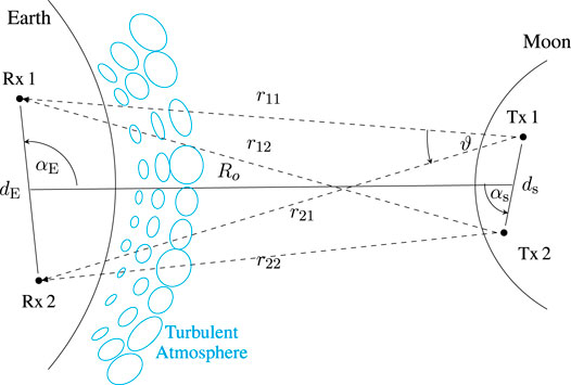
FIGURE 1. Application scenario (2 × 2 MIMO example) showing two lasers on Moon and two receivers on Earth introducing relevant positioning parameters (two-dimensional sketch, top view, dimensions not to scale).
Similar to the positions of the lasers, the location of the receiver array on Earth is specified by the geographical latitude ϕE and longitude θE. The distance between the receivers (receiver-baseline) is denoted by dE, and the orientation of the array on Earth with respect to the Earth’s equatorial plane is defined by the angle δE. We apply here the same convention as for the angle δs. To give an example: If δE = 0°, the receiver array is oriented in East-West direction, i.e., both receivers are on the same geographical latitude. Thus, with the four parameters latitude ϕE, longitude θE, antenna spacing dE and rotation angle δE the position of the receivers on Earth are exactly defined.
We denote the distance between the center of the Rx uniform linear array (ULA) on Earth and the center of the Tx ULA on lunar surface by Ro. Its value varies in dependence on the geographical location on Earth, the time and the array location on the Moon typically in the range of approximately 350,000 to 400,000 km. Moreover, the distances between the lasers and the receiving telescopes are denoted by
In order to describe the orientation of the two ULAs with respect to each other, we introduce the three angles αE, αs and β as follows. The angles αs and αE are defined in the plane of the Tx ULA, and they describe the orientation of both ULAs with respect to each other (see Figure 1 again). If, for example, cos αs ⋅ cos αE = 1, the Tx ULA is broadside to the direction of the Rx ULA on Earth. The angle β specifies the rotation of the Rx ULA out of the plane of the Tx ULA (see Figure 2). If, for example, cos β = 1, the Rx ULA lies in the plane of the Tx ULA. We combine the three angles in a single parameter
which we call array reduction factor, because it describes the apparent reduction of the Tx array size as seen from the receiver and vice-versa. If arf = 1, both arrays are perfectly broadside to each other and the two lasers are seen from the Rx ULA with a separation of ds. If, on the other hand, arf = 0, the Tx array is perpendicular with respect to the receiver array. This can happen if, for example, the Rx ULA is rotated by β = 90° out of the plane of the Tx ULA. In the case of arf = 0, the two lasers are seen as a single point source from the receivers and cannot be resolved. We will use the parameter arf in the results section to discuss the capacity performance in dependence on the geometrical orientation of the two ULAs. It is an important parameter that must be considered in the system design.
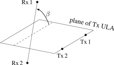
FIGURE 2. Graphical illustration of angle β.
2.1.2 Geometrical Constraints for Maximum Capacity
To benefit from the maximum capacity gain in a LOS channel, it is well-known that particular locations of the radiating and receiving elements are necessary (Driessen and Foschini, 1999). In fact, Driessen et al. have shown that the maximum MIMO capacity gain is possible in pure LOS channels if particular constraints on the positioning of the antennas in space are considered. Several works applied this concept to terrestrial wireless communications systems (Sarris and Nix, 2006; Bohagen et al., 2007) and to satellite communications (Schwarz et al., 2008). The key requirement is a minimum spacing between the radiating elements at the transmitter and the spacing between the receiving elements. In the case of ULAs at both sides of the link, the minimum required spacing between the elements is constraint by the relation (Bohagen et al., 2007)
This relation assumes that both ULAs are broadside to each other, i.e., arf = 1. In the more general case, the orientation of the arrays to each other have to be considered and it follows for (2) that
Figure 3 shows the result of (2) for various carrier wavelengths λ, spacing ds between the lasers on Moon and distances Ro between the arrays on Earth and on Moon. For a given distance Ro between the Tx and the Rx array and carrier wavelength λ, the optimal spacing between the elements of an array can be directly computed. A reduction of the element spacing dE at the receiver requires an increase of the element spacing ds at the transmitter and vice-versa.
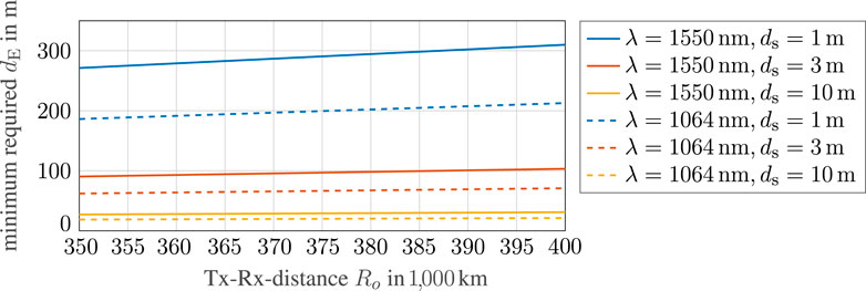
FIGURE 3. Minimum required receiver spacing dE of a 2 × 2 MIMO FSO system according to (2) as a function of distance between the array on Earth and the array on Moon.
2.1.3 System Design
The layout of lunar transmitter telescopes and Earth receiving stations is based on an asymmetric setup, where the smaller and, thus, lighter optical terminals shall be installed at the lunar surface. When employing, for example, 20 cm diameter apertures at the transmitter telescopes and considering a carrier wavelength of λ = 1,064 nm, a full width at half-maximum (FWHM)-divergence angle of approximately θdiv = 3.25 µrad is achieved. This divergence of θdiv = 3.25 µrad will produce spot sizes of about 1.2 km diameter on Earth-ground. They are wide enough for both receivers (i.e. θdiv ≫ ϑ, see again Figure 1) being able to appropriately receive the signals from both laser transmitters, even for a receiver-baseline dE of several hundreds of meters as shown in Figure 3.
This layout assumes correction of phase-front errors induced from index-of-refraction turbulence (IRT) through Adaptive-Optics (hence, the need for a wavefront-sensor). Precise pointing from Moon to ground has been demonstrated even by an orbiting probe (Boroson et al., 2014), and shall be near-perfect with transmitters positioned statically on the lunar surface. A Laser-power of 1 W and more can be achieved from frequency-stable 1,064 nm laser sources together with optical fiber amplifiers.
Effects from atmospheric turbulence manifest in intensity-scintillations with structure sizes ρI in the cm-to-dm-range, and in wavefront-distortions structure sizes (Fried-parameter) also in the cm-to-dm-range. The former is compensated through aperture-averaging over the large receiver-antenna of 1 m in diameter, whereas the latter is corrected through Adaptive-Optics Techniques. We assume a Gaussian noise model for the coherent signal reception with a sensitivity of 50 Photons per bit, as a Poisson-model would only be required for a single photon-counting direct-detection receiver, which is not within the scope of this analysis (Giggenbach and Mata-Calvo, 2015).
2.2 System and Channel Model
Based on the link scenario we have described in Section 2.1, the receive signal vector
with
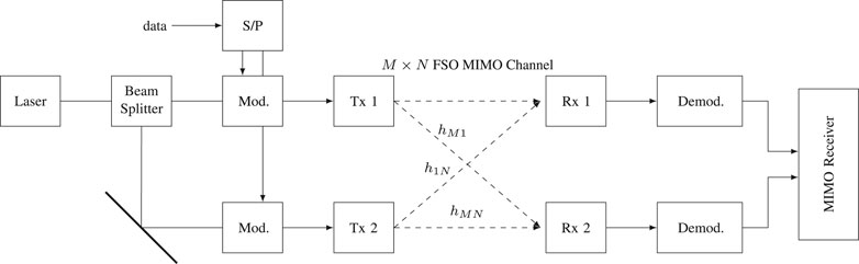
FIGURE 4. Simplified block diagram of the transmitter-receiver architecture.
The channel matrix
where hmn denotes the complex channel coefficient at row m and column n of H. The parameter
models the free space propagation loss, where φ stands for the common carrier phase that can be assumed to be zero without loss of generality (w.l.o.g.). The value of amn is very similar for all m, n, because the difference between the path lengths is very small compared to their mean total length. Thus, we can apply the approximation amn ≈ a in (6) without loss of accuracy.
The parameter bmn, with 0 < bmn ≤ 1, denotes the additional amplitude attenuation through the atmosphere. The actual value of this parameter depends on various factors, such as the length of the slant path through the atmosphere, wavelength of the laser and aerosol and molecular constituents (Hemmati, 2006). Its value generally varies during a passage of the Moon. This parameter is important to be considered in the link budget and system design to guarantee a minimum required system availability. Its modeling is treated thoroughly in (Shrestha et al., 2018) and in particular in (International Telecommunication Union, 2015). However, as these additional attenuations affect identically the laser beams of both systems, and as our focus is on the direct comparison of the channel capacity between the MIMO and the single input single-output (SISO) system, it is reasonable to neglect the variation of this parameter in this first comparison study. We, therefore, set
in this model, i.e., we consider a fixed atmospheric loss of 3 dB for the rest of the paper. This simplification does not affect the general results in this paper.
The parameter ξmn models the phase variation due to the turbulent atmosphere. Assuming a transmitter-baseline ds in the order of 1 to 10 m, the separation angle of both transmitters is less than or equal to approximately 10 m/400,000 km = 25 nrad. Both transmitters appear as a single source for each receiver since they cannot be resolved optically by one ground telescope, whose angular resolution typically amounts to more than 1 µrad. Both sources will, thus, perfectly fit inside one isoplanatic patch. The isoplanatic angle (IPA) describes the angular cone of common index-of-refraction turbulence (IRT) inside the atmosphere (Andrews and Phillips, 2005). It is derived from the height-profile of the IRT, and corresponds to around 20 µrad in typical situations, down to a few µrad in stronger turbulence, but is always larger than the separation angle of the transmitters. It is, therefore, reasonable to assume that any influence from IRT will affect both transmitted signals (Tx 1 and Tx 2) at a particular receiver aperture (Rx 1 or Rx 2) equally. Hence, the modeling of the phase variation due to the turbulent atmosphere can be simplified to
i.e. we assume no differential phase-offset between the beams ending at the m-th receiver.
In addition to the parameter ξm, a common phase piston variation for both laser beams needs to be considered. Optical phase piston in the atmosphere are discussed in (Conan et al., 1995; Karr, 2007) showing a phase front error of about 1 μrad at 1,064 nm and 1,550 nm. This effect can be modeled as a degradation of the receive signal-to-noise-ratio (SNR) (Fried, 1967), and it will, therefore, be considered in the example link budget in the results section. Applying now (6), (7) and (8) to (5), and assuming M = N = 2, the channel matrix H is then given by
2.3 Performance Criterion
To evaluate the performance of the optical FSO MIMO system, we apply the MIMO channel capacity. The capacity of a MIMO system with no channel knowledge at the transmitter is given by (Telatar, 1999)
where
The MIMO channel capacity is maximum if all eigenvalues of the channel transfer matrix H are equal. In this case, the MIMO channel forms
The channel capacity of an equivalent SISO FSO laser link is given by
Comparing (12) with (11) and assuming a symmetric MIMO system with M = N antennas, the capacity gain of MIMO compared to SISO becomes evident, which is
Please note that in this comparison throughout the paper the total radiated transmit power has been normalized by the number of lasers N. Hence, the total receive SNR per optical receiver of the MIMO system equals that of the equivalent SISO system. We will use
3 Results
3.1 Simulation Parameters
For the following analysis we assume the simulation parameters as summarized in Table 1. The two-element laser ULA is located on the Moon’s prime meridian on the equator and is rotated by −40° with respect to the Moon equator plane. The lasers are separated by ds = 5 m and radiating with 0.5 W each at 1,064 nm. The two receiving telescopes are at ϕE = 28° N, θE = 16.5° W (a location on Tenerife, Spain) and have a spacing of dE = 47 m. As an example, and without loss of generality, we consider the night from 26th to April 27, 2021.
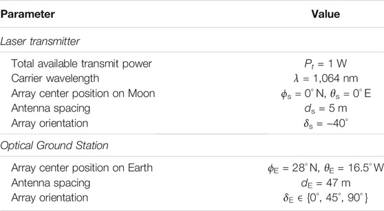
TABLE 1. Simulation parameters of the 2 × 2 MIMO Moon-to-Earth laser link.
Figure 5 shows the Moon’s elevation and azimuth angle as seen from the optical ground station (OGS) location on Earth (upper plot) as well as the distance Ro between the arrays (lower plot). The elevation angle at zenith is almost 50°, and the transmitter-receiver distance varies between approximately 351,600 to 354,400 km for an elevation angle not less than 20°. Please note again that this Moon orbit during this particular night and the location of the OGS have been chosen as an example. Other parameters are possible too, and they would lead to similar results.
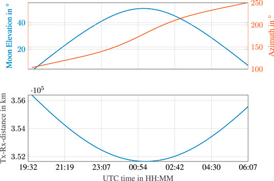
FIGURE 5. Elevation and azimuth of the Moon as seen from Earth (upper plot) and distance between receiving array and transmitting array (lower plot) at April 26th to 27th.
Table 2 shows an example link budget based on the transmitter-receiver design as discussed in Section 2.1. At an elevation angle of 30°, the Tx-Rx-array distance is approximately Ro = 354,000 km (please refer to Figure 5 again) leading to a free space propagation loss of
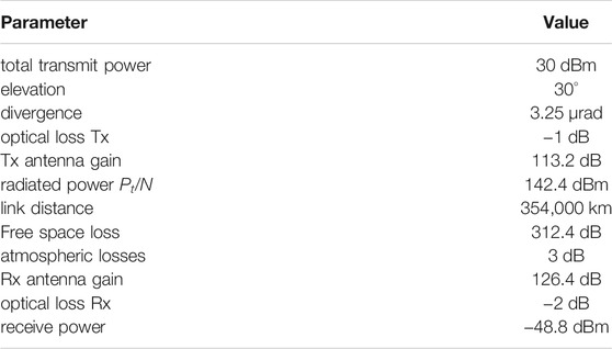
TABLE 2. Example link budget estimation.
3.2 Simulation Results and Discussion
The MIMO channel capacity
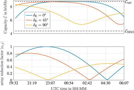
FIGURE 6. MIMO channel capacity in comparison to SISO capacity (upper plot) and the corresponding array reduction factor
Moreover, in order to analyze the dependence of the MIMO capacity on the geometry between both ULAs, three orientation angles of the Rx ULA from 0° to 90° are simulated. The curves clearly show the dependence of the MIMO capacity on the geometry between the two ULAs. Since the orientation of the Tx array with respect to the receiver array is changing over time as the Moon passes by, the capacity is varying and
For all three curves the corresponding absolute value of the array reduction factor
Our simulation results show that it is basically possible to achieve the maximum MIMO capacity for an FSO communications laser link between Earth and Moon. The necessary spacings between the lasers and the telescopes are in the order of some meters up to a few tens of meters for typical carrier wavelengths between 1,064 and 1,550 nm. These dimensions are manageable in practice to realize an FSO MIMO communications system having all necessary receiving equipment at a single site and all transmitter equipment closely together on the Moon surface. Assuming a minimum elevation angle of 20°, a beneficial positioning parameter setup can be found providing capacity gains that are close to the maximum during a complete passage of the Moon. For a constant connection with high MIMO capacity during a complete lunar orbit, multiple MIMO receive telescopes could be deployed around the globe. Such a network with the name Linearly Dispersed Optical Subnet (LDOS) has already been proposed assuming single lasers at each location (Hemmati, 2006).
4 Conclusion
As lunar exploration is again getting into focus of different space agencies and commercial players in the field, a broadband communication connection to Earth’s Moon will become highly desireable. Spatial multiplexing by LOS MIMO applied to FSO communications could provide such a high-rate data link. Its realization via multiple transmitters at the lunar surface and multiple receivers on ground appears viable under reasonable assumptions for the system design, providing signal capacities many times higher than achieved by SISO topologies.
Our analyses has been centered to the geometrical characteristics of Moon-to-Earth links employing ULAs. Hence, atmospheric effects have only been treated superficially to assess their fundamental influence on the optical LOS MIMO channel. We find that atmospheric attenuation and IRT pose no show stoppers for this technology, however, we acknowledge the importance of advanced investigations in this respect and propose further work considering different fading models than AWGN. Moreover, when it comes to the practical exploitation of the capacitiy gain described herein, usually the timely evaluation of the channel state information (CSI) at the receiver or the transmitter is a necessary prerequisite for the signal processing. Bearing in mind the long link distance and typical coherence times of atmospheric turbulence in the order of tens of milliseconds, CSI determination can be challenging. On this backdrop, link elevation potentially becomes a driving parameter and should be trated with special care.
As cloud-cover poses a fundamental stoppage for FSO transmissions, potential ground sites are to be chosen with care and an appropriate site-diversity scheme, for example an LDOS, should be considered to mitigate link outages and provide decent link availabilities.
Eventually, the work at hand concentrates on the space-to-ground link. We expect the opposite transmission (from the Earth to the Moon) to hold new challanges, as atmospheric turbulence affects the signalling much closer to the transmitters. Then, for example, beam-wander and phase delays will probably come into play and could deteriorate the LOS MIMO channel.
Data Availability Statement
The original contributions presented in the study are included in the article/Supplementary Material, further inquiries can be directed to the corresponding author.
Author Contributions
All authors listed have made a substantial, direct, and intellectual contribution to the work and approved it for publication.
Conflict of Interest
The authors declare that the research was conducted in the absence of any commercial or financial relationships that could be construed as a potential conflict of interest.
Publisher’s Note
All claims expressed in this article are solely those of the authors and do not necessarily represent those of their affiliated organizations, or those of the publisher, the editors and the reviewers. Any product that may be evaluated in this article, or claim that may be made by its manufacturer, is not guaranteed or endorsed by the publisher.
References
Andrews, L. C., and Phillips, R. L. (2005). Laser Beam Propagation Through Random Media (1000 20th Street. Bellingham, WA 98227-0010 USA: SPIE. doi:10.1117/3.626196
Araki, T. (2021). “A Trade-Off Study of Lunar-Earth Optical Communication Links,” in International Conference on Space Optics — ICSO 2020. Editors Z. Sodnik, B. Cugny, and N. Karafolas, 69. SPIE. doi:10.1117/12.2599331
Barry, J. R., and Lee, E. A. (1990). Performance of Coherent Optical Receivers. Proc. IEEE 78, 1369–1394. doi:10.1109/5.58322
Bayaki, E., Schober, R., and Mallik, R. K. (2009). Performance Analysis of MIMO Free-Space Optical Systems in Gamma-Gamma Fading. IEEE Trans. Commun. 57, 3415–3424. doi:10.1109/TCOMM.2009.11.080168
Bohagen, F., Orten, P., and Oien, G. E. (2007). Design of Optimal High-Rank Line-Of-Sight MIMO Channels. IEEE Trans. Wireless Commun. 6, 1420–1425. doi:10.1109/TWC.2007.348338
Boroson, D. M., Robinson, B. S., Murphy, D. V., Burianek, D. A., Khatri, F., Kovalik, J. M., et al. (2014). “Overview and Results of the Lunar Laser Communication Demonstration,” in Free-Space Laser Communication and Atmospheric Propagation XXVI. Editors H. Hemmati, and D. M. Boroson (San Francisco, California: International Society for Optics and Photonics (SPIE), 8971, 213–223. doi:10.1117/12.2045508
Bussey, B., Clarke, S. W., Jenkins, J., and Bailey, B. E. (2019). “NASA’s Lunar Discovery and Explorartion Program,” in AGU Fall Meeting Abstracts, 2019, PA54B–11.
Caplan, D. O. (2008). “Laser Communication Transmitter and Receiver Design,” in Free Space Laser Communications (Springer), 109–246.
Conan, J.-M., Rousset, G., and Madec, P.-Y. (1995). Wave-front Temporal Spectra in High-Resolution Imaging through Turbulence. J. Opt. Soc. Am. A. 12, 1559. doi:10.1364/JOSAA.12.001559
Deng, P., Kavehrad, M., Liu, Z., Zhou, Z., and Yuan, X. (2013). Capacity of Mimo Free Space Optical Communications Using Multiple Partially Coherent Beams Propagation through Non-kolmogorov strong Turbulence. Opt. Express 21, 15213–15229. doi:10.1364/oe.21.015213
Driessen, P. F., and Foschini, G. J. (1999). On the Capacity Formula for Multiple Input-Multiple Output Wireless Channels: a Geometric Interpretation. IEEE Trans. Commun. 47, 173–176. doi:10.1109/26.752119
Evans, C. A., Young, K. E., Graff, T. G., Bleacher, J. E., and Noble, S. K. (2020). “Training Artemis Astronauts to Explore the Moon,” in American Geophysical Union Fall 2020 Meeting.
Fong, T. (2018). “The Gateway: Enabling Infrastructure for a new era of Lunar Robotics,”. NASA Exploration Science Forum.
Fried, D. L. (1967). Optical Heterodyne Detection of an Atmospherically Distorted Signal Wave Front. Proc. IEEE 55, 57–77. doi:10.1109/PROC.1967.5377
Frigyes, I., Csurgai-Horvath, L., and Horvath, P. (2012). “FSO-MIMO Behavior in Variable Atmospheric Turbulence — an Asymptotic Approach,” in 2012 IEEE Globecom Workshops (IEEE), 1198–1202. doi:10.1109/GLOCOMW.2012.6477750
Ghassemlooy, Z., Popoola, W. O., Ahmadi, V., and Leitgeb, E. (2009). Lecture Notes of the Institute for Computer Sciences, Social-Informatics and Telecommunications Engineering, 16, 6161–7373. doi:10.1007/978-3-642-11284-3_7MIMO Free-Space Optical Communication Employing Subcarrier Intensity Modulation in Atmospheric Turbulence Channels LNICST.
Giggenbach, D., and Mata-Calvo, R. (2015). Sensitivity Modeling of Binary Optical Receivers. Appl. Opt. 54, 8254–8259. doi:10.1364/AO.54.008254
Giggenbach, D., Moll, F., Schmidt, C., Fuchs, C., and Shrestha, A. (2018). Optical On-Off Keying Data Links for Low Earth Orbit Downlink Applications, Vol. 79. Stevenage, United Kingdom: The Institution of Engineering and Technology, 307–339. of IET TELECOMMUNICATIONS SERIES.
Giggenbach, D., and Moll, F. (2017). “Scintillation Loss in Optical Low Earth Orbit Data Downlinks with Avalanche Photodiode Receivers,” in 2017 IEEE International Conference on Space Optical Systems and Applications (ICSOS) (IEEE), 115–122. doi:10.1109/ICSOS.2017.8357220
Goswami, N. (2020). India's Space Program, Ambitions, and Activities. Asia Policy 27, 43–49. doi:10.1353/asp.2020.0022
Hajjarian, Z., Fadlullah, J., and Kavehrad, M. (2009). MIMO Free Space Optical Communications in Turbid and Turbulent Atmosphere (Invited Paper). Jcm 4, 524–532. doi:10.4304/jcm.4.8.524-532
Hemmati, H. (2006). Deep Space Optical Communications. Hoboken, NJ, USA: John Wiley & Sons. doi:10.1002/0470042419
Henniger, H., and Wilfert, O. (2010). An Introduction to Free-Space Optical Communications. Radioengineering 19, 203–212.
Horwath, J., David, F., Knapek, M., and Perlot, N. (2005). “Coherent Transmission Feasibility Analysis,” in Proceedings of SPIE 5712, Free-Space Laser Communication Technologies XVII, April 18, 2005. doi:10.1117/12.589196
International Telecommunication Union (2015). ITU-R P. 1621 Propagation Data Required for the Design of Earth-Space Systems Operating between 20THz and 375 THz. Tech. Rep. Geneva: International Telecommunications Union.
Israr, A., Israr, A., and Khan, F. (2019). Optimal Modulation Technique for Mimo Fso Link. Wireless Pers Commun. 109 (2), 695–714. doi:10.1007/s11277-019-06586-6
Jensen, M. A., and Wallace, J. W. (2004). A Review of Antennas and Propagation for Mimo Wireless Communications. IEEE Trans. Antennas Propagat. 52, 2810–2824. doi:10.1109/TAP.2004.835272
Karr, T. J. (2007). Atmospheric Phase Error in Coherent Laser Radar. IEEE Trans. Antennas Propagat. 55, 1122–1133. doi:10.1109/tap.2007.893364
Li, C., Wang, C., Wei, Y., and Lin, Y. (2019). China's Present and Future Lunar Exploration Program. Science 365, 238–239. doi:10.1126/science.aax9908
Matsumoto, K., Kamimori, N., Takizawa, Y., Kato, M., Oda, M., Wakabayashi, S., et al. (2006). “Japanese Lunar Exploration Long-Term Plan, Acta Astronautica 59, ” in Space for Inspiration of Humankind, Selected Proceedings of the 56th International Astronautical Federation Congress, Fukuoka, Japan, October 2005, 6817–7621. doi:10.1016/j.actaastro.2006.02.020
Mietzner, J., Schober, R., Lampe, L., Gerstacker, W., and Hoeher, P. (2009). Multiple-antenna Techniques for Wireless Communications - a Comprehensive Literature Survey. IEEE Commun. Surv. Tutorials 11, 87–105. doi:10.1109/surv.2009.090207
Puryear, A., and Chan, V. W. S. (2010). “Optical Communication over Atmospheric Turbulence with Limited Channel State Information at the Transmitter,” in 2010 IEEE Global Telecommunications Conference GLOBECOM 2010 (IEEE), 1–6. doi:10.1109/GLOCOM.2010.5683796
Sarris, I., and Nix, A. (2006). Design and Performance Assessment of Maximum Capacity MIMO Architectures in Line-Of-Sight. IEE Proc. Commun. 153, 482. doi:10.1049/ip-com:20050393
Schwarz, R. T., Delamotte, T., Storek, K.-U., and Knopp, A. (2019). MIMO Applications for Multibeam Satellites. IEEE Trans. Broadcast. 65, 664–681. doi:10.1109/TBC.2019.2898150
Schwarz, R. T., Knopp, A., Ogermann, D., Hofmann, C. A., and Lankl, B. (2008). “Optimum-capacity MIMO Satellite Link for Fixed and mobile Services,” in 2008 International ITG Workshop on Smart Antennas (Darmstadt, Germany: WSA), 209–216. doi:10.1109/wsa.2008.4475561
Seas, A., Robinson, B., Shih, T., Khatri, F., and Brumfield, M. (2018). “Optical Communications Systems for Nasa’s Human Space Flight Missions,” in International Conference on Space Optics.
Shrestha, A., Giggenbach, D., Moll, F., and Fuchs, C. (2018). “Atmospheric Transmission Spectrum for Space to Ground Free Space Optical Communications,” in Proc. of the International Conference on Space Optics (ICSO).
Telatar, E. (1999). Capacity of Multi-Antenna Gaussian Channels. Eur. Trans. Telecomm. 10, 585–595. doi:10.1002/ett.4460100604
Wells, J. (2009). Faster Than Fiber: The Future of Multi-G/s Wireless. IEEE Microwave 10, 104–112. doi:10.1109/MMM.2009.932081
Wilson, S. G., Brandt-Pearce, M., Cao, Q., and Leveque, J. H. (2005). Free-Space Optical MIMO Transmission With$Q$-ary PPM. IEEE Trans. Commun. 53, 1402–1412. doi:10.1109/TCOMM.2005.852836
Woerner, J., and Foing, B.Moon Village International Support Group (2016). “The “Moon Village” Concept and Initiative,” in Annual Meeting of the Lunar Exploration Analysis Group, 5084.Vol. 1960
Zhang, J., Dai, L., Han, Y., Zhang, Y., and Wang, Z. (2015). On the Ergodic Capacity of MIMO Free-Space Optical Systems over Turbulence Channels. IEEE J. Select. Areas Commun. 33, 1925–1934. doi:10.1109/JSAC.2015.2452631
Keywords: optical lunar downlink, lunar orbit geometry, channel capacity, multiple-input multiple-output, free-space optic, deep-space laser communications, line-of-sight channel
Citation: Schwarz RT, Giggenbach D, Knopp MT and Knopp A (2021) A Laser Link From Lunar Surface Employing Line-of-Sight MIMO. Front. Space Technol. 2:750938. doi: 10.3389/frspt.2021.750938
Received: 31 July 2021; Accepted: 13 September 2021;
Published: 25 October 2021.
Edited by:
Nicolò Mazzali, European Space Research and Technology Centre (ESTEC), NetherlandsReviewed by:
Ha Duyen Trung, Hanoi University of Science and Technology, VietnamShkelzen Cakaj, Polytechnic University of Tirana, Albania
Copyright © 2021 Schwarz, Giggenbach, Knopp and Knopp. This is an open-access article distributed under the terms of the Creative Commons Attribution License (CC BY). The use, distribution or reproduction in other forums is permitted, provided the original author(s) and the copyright owner(s) are credited and that the original publication in this journal is cited, in accordance with accepted academic practice. No use, distribution or reproduction is permitted which does not comply with these terms.
*Correspondence: Dirk Giggenbach, ZGlyay5naWdnZW5iYWNoQGRsci5kZQ==